Fein DDSk 672 User manual

DDSk
672
To be handed to the workshop
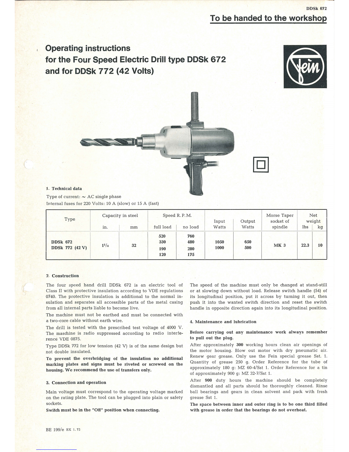
Operating instructions
for the Four Speed Electric Drill type DDSk
672
and for DDSk
772
(42
Volts)
L
Jechnical
data
Type
of
current:
~
AC
single
phase
Int.ernal
fuses
for
220
Volts:
10 A (slow)
or
15 A (fast)
Capacity
in
steel
Speed
R.
P.M.
Morse
Taper
Net
Type
Input
Ou
tpu
t
socket
of
weight
in. I
mm
full
load
I
no
load
Watts
I
Watts
spindle
lbs
J
kg
I 520
DDSk 612 I 330
pj,
32
DDSk 112
(42V)
I
190
I 120
2.
Construction
The
four
spee
d
hand
drill
DDSk
672
is
an
el
ectr
ic
tool
of
Class
II
with
protective
insulation
according
to
VDE
regulations
0740.
The
prot
ec
tive
insulation
is
additional
to
th
e
normal
in-
sulation
and
separates
all
accessible
parts
of
the
metal
casing
from
all
internal
parts
liable
to
become
live.
The
machine
must
not
be
ea
rth
ed
and
must
be
connected
with
a
two-cor
e
cab
le
without
earth
wire.
The
drill
is
tested
with
the
pr
escribe
d
test
vo
ltag
e
of
4000 V.
The
maschine
is
radio
suppressed
according
to
radio
interfe-
rence
VDE 0875.
Type
DDSk 772
for
low
tension
(42 V) is
of
the
same
design
but
not
double
insulated.
To
prevent
the
overbridging
of
the
insulation
no
additional
marking
plates
and
signs
must
be
riveted
or
screwed
on
the
housing.
We
recommend
th
e
use
of
transfers
only.
3.
Connection
and
operation
Main
voltage
must
correspond
to
the
operating
voltage
marked
on
the
rating
plate.
The
tool
can
be
plugged
into
plain
or
safety
sockets
.
Switch
must
be
in
the
"Off"
position
when
connecting.
BE
199/e
BX
1. 73
760
480 1050 650
MK3
22.3 10
280 1000 500
115
The
speed
of
the
machine
must
only
be
cha
nged
at
stand-s
till
or
at
slowing
down
without
load
.
Release
switch
handle
(54)
of
its
longi
tu
dinal
position
,
put
it
across
by
t
urni
ng
it
out,
then
push
it
in
to
the
wanted
switch
direction
and
reset
the
switc
h
handle
in
opposite
direction
again
into
its
longitudinal
position.
4.
Maintenance
and
lubrication
Before
carrying
out
any
maintenance
work
always
remember
to
pull
out
the
plug.
After
approximately
300
working
hours
clean
ai
r
openings
of
the
motor
housing.
Blow
out
motor
with
dry
pneu
matic
air.
Renew
gear
grease.
Only
use
th
e
Fein
s
peci
al
grease
Sst
. 1.
Quantity
of
g
re
ase
250
g.
Order
Refe
ren
ce
for
th
e
tube
of
approx
imat
ely 180 g:
MZ
60-4/
Sst
1.
Ord
er
Re
feren
ce
for
a tin
of
approx
i
mately
900 g: MZ 32-7/
Sst
1.
After
900
duty
hours
the
machine
should
be
completely
dism
antled
and
all
parts
should
be
thorou
ghly
cleane
d. Rinse
ball
bearings
and
gears
in
cle
an
solvent
and
pack
with
fresh
grease
Sst
1.
The
space
between
inner
and
outer
ring
is
to
be
one
third
filled
with
gr
ease
in
order
that
the
bearings
do
not
overheat.

26
29
25 24
I
~
s
~
0
I I
68
67
Il0f
~
64
63
65 62
66 fi
rW
I I
12
11
I
9
-Cj)
I
r
_____
........
-~-----_.....
-------~
--------~-
_
_...,
_..J
! .
-til
I
I
I
t
I
I
I
....
8- - . 73- -
/~
-
,_,
5
79
_/~
-
--
4
@ • D
0 I
45
146
43
44
41
J I i
~0-
39
~~.J--~~-·
-
··-
-~
..
...
;)
j~
)
83
:•
-
---.
·h
' t 82
,
81
85
I
_J_
1
~-
-72
6
8
~
!
9
-
-~
61
60
f
71-
1
111
-

0
z
Order
:><
~
....
Reference
0
<0
0..
1-12
MK3-95-21)
1
1
MK
3-95 1
2 PT 5d-M5 2
3 SR 33-M5x25 2
4 PT 27-31 2
5 SR 2-M4x10 4
6
MK
13-18 1
7
EZ
12-48-1 2
a 8 EZ11-61 2
9 EZ 13-9 2
b
10
state
type
and
voltage
1
11
PT 37-8 2
12
SR 1-M5x55 I 2
b 13-17
state
type
1
and
v
oltage
14
FL
4-7-1 1
18-58 LA 9-58-2 1
18 LA 6-153 1
19
BF 1-5x20 1
20-58
LA
9-58-1 1
20 LA 9-58 1
23
DJ
8-21 1
24· LK 6a-12 1
25 LK 7-24 1
26
WB
2-37 1
27
PT
11-56 1
27a
DJ
1-62 1
27b
PT
11-57 1
28
LK
16-36 1
29
BF 21-6x6x16 1
30 ZR 15-7x1,5 1
31
MR
3-M16x1,5 1
33 LK 1-7 4
34
WB
16-5 1
35 ZR 15-19x1 1
36, 37 ZR 15-10x1 ,25-1 1
38
RJ
16-23 1
39 ZR 16-3x1,25 1
b 40 ZR 15-9x1,25 1
41
LK 1-47 2
42
ZR 16-5x1,5 1
43
PT
1-M 14 1
44
RJ
30a-15x1 1
4S,
46 1ZR 1-25x1,25-1 1 I
47
RJ
16-43 1
48
BF17-174
1
49
BF17-193
1
50 BF 17-173 1
51
BF 17-177 1
52 BF17-192 1
53 BF 38-3x18 3
54
SA
5-45 2
55 BF 16-86 2
56 FD 1-202 2 I
58 BF 38-2x12 2 I
I
1)
State
voltage
Component Parts
Description
motor
housing,
assembled
motor
housing
securing
plate
hexagon
socket
screw
cover
cylindrical
screw
insulator
carbon
holder,
assembled
carbon
brush
carbon
holder
cap
stator
with
winding
secu
'
ring
plate
hexagon
screw
armature
with
winding,commutator
and
fan,
balanced
fan
wheel,
assembled
drill
head,
assembled
intermediate
bearing
with
greaser
MZ
31-1
cylindrical
pin
outer
bearing,
assembled
outer
bearing
sealing
ring
needle
bearing
axial
ball
bearing
drill
shaft
disc
felt
ring
disc
ball
bearing
fitting
key
gear
wheel,
43
teeth
hexagon
nut
ball
bearing
switch
shaft
gear
wheel,
46
teeth
gear
wheel,
assembled,
19/33
teeth
circlip
Seeger
double
pinion,
13/19
teeth
gear
wheel,
30
teeth
ball
bearing
pinion,
13
teeth
stop
ring
circlip
Seeger
gear
wheel,
assembled,
37/40
teeth
circlip
Seeger
switch
bolt
switch
pin
switch
pin
switch
bolt
switch
pin
clamping
sleeve
switch
handle
pressure
pin
spring
clamping
sleeve
b
b
b
a
a
a
a
a
a
a
0
z
Order
~
....
Reference
<0
0..
60
FD 5-19
61
LK 16-1
62
LK 16-2
63
PT
11-52
64
DJ
1-55
65
RJ
30a-12x1
66
PT
10-46
67
I PT 5d-M4
68 SR 33-M4x25
69
PT
5d-M6
70
SR
35-M6x
100
71
SR33-M5x25
72
SR33-M5x20
73
JS
6-24
74
a PT 20-20
77-84
GH4-64-4
77-79
GH
4-64-1
77
GH
4-64
78
GH4-65
79
SR3-M4x25
80
EZ
1-73
81
PT 31-21
82 SR3-M3,5x10
83
JS
13-90
84 EZ 22-32
85 EZ 7-105
1-12
MK
3-95-3
7 EZ 12-47-3
8 EZ 11-56
73
JS
13-100
73a
JS
13-101
77-84
GH
4-64-26
80
EZ
1-93
82 SR3-M3,5x15
83
JS
13-52
85 EZ 6-140
74
MZ
20-24
MZ
17-4
z10-10
z 10-11
EZ 11-61
EZ
11-56
l
r:
10
Description
I
2 flat
spring
1
ball
bearing
1
ball
bearing
1
disc
1
felt
ring
1
circlip
Seeger
1
end
cover
3
securing
plate
3
cylindrical
screw
4
securing
plate
4
hexagon
socket
screw
4
hexagon
socket
screw
4
hexag~n
socket
screw
1
insulation
sleeve
1
handle
flange
1
handle,
assembled
with
switch
1
handle,
assembled
1
lower
handle
section
1
upper
handle
section
2
fillister
screw
1 switch, 2
poles
1
cable
clamping
bridge
2
fillister
screw
1
cable
protecting
sleeve
1
capacitor
1
complete
cable
Parts
ior
low
tension
(42
Volts)
1
motor
housing,
assembled
2
carbon
holder,
assembled
2
carbon
brush
2
insulating
hose
2
insulating
hose
1
handle,
assembled
with
switch
1
switch
2
fillister
screw
1
cable
protecting
sleeve
1
cable
Accessories
1
handle
1
drill
drift
1
spanner
1
spanner
2
spare
carbon
brush
(220 V)
2
spare
carbon
brush
(42 V)

Ple,ase
be
sure that all
electric
and
plastic
parts are
only
cleaned
dry.
For
good
and
adequate
lubrication
and
to
avoid
overheating
it
is
important
to
pack
gearing
and
bearings
with
the
grades
and
quantities
of
grease.
Worn
carbon
brushes
automatically
switch
off
the
machine
after
reaching
their
minimum
length.
Only
use
Fein
carbon
brushes.
After
checking
the
carbon
brushes
make
sure
to
refit
them
in
their
original
position
and
check
that
they
move
easily
in
their
holder.
After
fitting
new
brushes,
run
tool
unloaded
for
about
15
minutes
to
allow
brushes
to
bed
in.
In
order
to
prevent
accidents
check
cable
and
connections
at
both
sides
at
regular
intervals.
No
claims
can
be
entertained
for
damage
due
to
negligent
main-
tenance
and
inadequate
lubrication.
5. Stationary
use
in
the
bench
d!ill
stand
If
the
machine
remains
fixed
to
the
bench
drill
stand
the
gear
grease
is
not
sufficiently
changed
.
Regrease
once
a
week
with
the
grease
gun
at
the
greaser
(18).
After
operation
do
not
keep
the
magnetic
bench
drill
stand
with
the
fixed
machines
in
a
vertical
position
but
in
a
horizontal
one
so
that
the
gear
grease
is
distributed
equally
.
6.
Dismantling
The
tool
should
only
be
taken
apart
by
an
expert.
1.
Pull
plug
from
socket.
2.
Take
off
motor
housing
cover
(4).
unscrew
carbon
holder
caps
(9)
and
take
out
carbon
brushes
(8)
. .
3.
Take
off
handle
cover
(78).
loosen
supply
cable
and
interior
connection
cable
from
switch
(80).
Take
out
switch
and
clamp
off
cable
(85)
together
with
protecting
sleeve
(83)
from
clamping
bridge
(81).
4.
Remove
lower
handle
section
(77).
draw
out
insulation
sleeve
(73).
5.
Unscrew
four
screws
(70),
take
outer
bearing
(20),
inter-
mediate
bearing
(18)
with
armature
(13)
off
motor
housing
(1)
.
6.
Push
out
two
clamping
sleeves
(53)
of
shift-bolt
(48)
and
one
clamping
sleeve
(53)
of
shift-bolt
(51)
by
means
of
a 3
mm
pin
in
direction
of
boring
shaft,
pull
out
switch
handles
(54)
with
the
two
switch
pins
(49)
and
(52)
at
the
side
.
Remove
the
two
switch
pins
(48)
and
(51)
and
pay
attention
to
the
easily
accessible
clamping
sleeves
(53).
7.
Draw
countershafts
(34).
(39)
and
(42)
out
of
outer
bearing
(20)
.
8.
Unscrew
hexagon
nut
(31),
draw
off
drill
shaft
gear
wheel
(30),
take
out
fitting
key
(29),
push
out
drill
shaft
(26).
Pay
attention
to
washers!
9.
Unscrew
screws
(68)
completely
of
intermediate
bearing.
Push
out
armature
(13)
with
fan
and
ball
bearing
(62)
.
lO.
Only
in
case
of
damage
take
out
insulator
(6)
with
stator
(10)
after
pulling
supply
cable
through
the
lateral
boring
into
the
housing
and
unscrewing
screws
(3)
.
Re-assemble
in
reverse
sequence.
7.
Repair
and
Spare Parts
We
recommend
our
Fein
Service
Stations
to
carry
out
all
over-
haul
and
repair
work
quickly
and
expertly.
Please
quote
Order Reference
when
ordering
spare
parts or
send
in
sample
part, stating
the
type
of
the
machine.
We
draw
your
attention
to
the
need
to
carry
out
a
high
voltage
test
in
accordance
with
your
local
regulations
(or VDE
regu-
lation
0740)
before
·
taking
a
tool
into
service
after
any
r~pair
carried
out
by
your
own
staff.
8.
Tools
for
Assembling
and
Disassembling
Tool
for
disassembling
carbon
holders.
Order
Reference:
ZSo
77-7-1.
Spanner
for
mounting
carbon
holders.
Order
Reference:
ZSo 71-6.
~
I
C.
This manual suits for next models
1
Other Fein Drill manuals

Fein
Fein ASz 648 d User manual

Fein
Fein KBE 35 (A) Setup guide

Fein
Fein kbb38x User manual

Fein
Fein KBE30 User manual

Fein
Fein BOZ 32-4M Setup guide

Fein
Fein KBM 52 U User manual

Fein
Fein KBU 110-4 M Setup guide

Fein
Fein Slugger JMU 404 M User manual

Fein
Fein BOP 6 Setup guide

Fein
Fein Slugger JME Holemaker III User manual