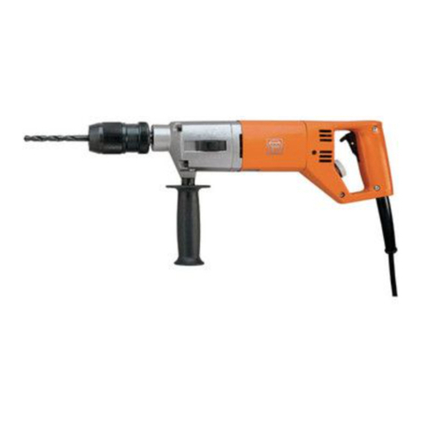
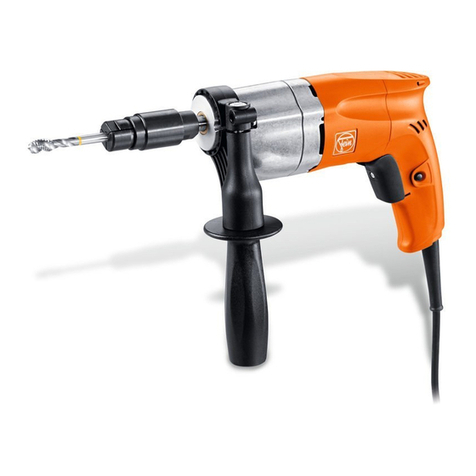
Fein DSk658-1 User manual

© C. & E. FEIN GmbH. Printed in Germany. Abbildungen unverbindlich. Technische Änderungen vorbehalten. 3 41 01 095 06 0 BY 2010.03 DE.
EN 60745, EN 55014, EN 61000-3-2, EN 61000-3-3
2006/42/EG, 2004/108/EG
Hammersdorf
Quality Manager Dr. Schreiber
Manager of R&D department
FEIN Service
C. & E. FEIN GmbH
Hans-Fein-Straße 81
D-73529 Schwäbisch Gmünd-Bargau
www.fein.com
DSk658-1 7 202 26
DSke658-1 7 202 27
DSke672 7 202 09
DDSk672 7 202 06
DDSk672-1 7 205 01
ASq672-1 7 205 03
3 41 01 095 06 0 - Titel 297.fm Seite 1 Dienstag, 16. März 2010 8:27 08

2
DSk658-1 DSke658-1 DSke672 DDSk672 DDSk672-1 ASq672-1
7 202 26 7 202 27 7 202 09 7 202 06 7 205 01 7 205 03
P
1
W 720 720 1050 1050 900 900
P
2
W 480 480 650 650 500 500
n
0
/min 360 150–360 120–270 175 170 100
/min 770 330–770 240–540 280 250 –
/min–––480450–
/min – – – 760 700 –
n
1
/min 200 100–200 110–185 120 100 60
/min 420 240–420 220–370 190 150 –
/min – – – 330 260 –
/min–––520420–
kg 5.5 5.8 8.8 9.4 9.6 10.6
mm 23/13 23/13 26/19 32 32 38
mm 28/20 28/20 32/23 40 40 –
mm 45/30 45/30 50/35 60 60 –
mm – – – – – M30/R1"
mm –––––40
d
1
mm – – – – – –
d
2
mm MT2 MT2 MT3 MT3 MT3 MT4
d
3
mm 53 53 63 63 63 63
L
wA
dB 92 92 97 99 92 92
K
wA
dB 3 3 3 3 3 3
L
pA
dB 81 81 86 88 81 81
K
pA
dB 3 3 3 3 3 3
L
pCpeak
dB 97 97 102 103 99 98
K
pCpeak
dB 3 3 3 3 3 3
h, D
m/s
2
0.6 0.6 1.6 1.3 0.9 0.4
m/s
2
1.5 1.5 1.5 1.5 1.5 1.5
Fe
Al
K
3
de 11 es 26 sv 41 pl 56
en 14 pt 29 fi 44 ru 59
fr 17 el 32 hu 47 zh(CM) 63
it 20 da 35 cs 50
nl 23 no 38 sk 53
3 41 01 095 06 0.book Seite 2 Montag, 15. März 2010 1:02 13

3
5
8 96
10
8
4
7
3 41 01 095 06 0.book Seite 3 Montag, 15. März 2010 1:02 13

4
1.
2.
DSk658-1
DSke658-1
DSke672
DDSk672
DDSk672-1
ASq672-1
3 41 01 095 06 0.book Seite 4 Montag, 15. März 2010 1:02 13

5
1.
2.
DSk658-1
DSke658-1
DSke672
DDSk672
DDSk672-1
ASq672-1
DSk658-1
DSke658-1
DSke672
DDSk672
DDSk672-1
ASq672-1
3 41 01 095 06 0.book Seite 5 Montag, 15. März 2010 1:02 13

6
1.
2.
3. 3.
DSk658-1
DSke658-1
DSke672
3 41 01 095 06 0.book Seite 6 Montag, 15. März 2010 1:02 13

7
1.
2.
3. 3.
DDSk672
DDSk672-1
3 41 01 095 06 0.book Seite 7 Montag, 15. März 2010 1:02 13

8
DSke658-1
DSke672
DDSk672-1
ASq672-1
3 41 01 095 06 0.book Seite 8 Montag, 15. März 2010 1:02 13

9
1.
2.
DSk658-1
DSke658-1
DSke672
DDSk672
DDSk672-1
ASq672-1
3 41 01 095 06 0.book Seite 9 Montag, 15. März 2010 1:02 13

10
DSk658-1
DSke658-1
DSke672
DDSk672
DDSk672-1
ASq672-1
ASq672-1
3 41 01 095 06 0.book Seite 10 Montag, 15. März 2010 1:02 13

11
de
Originalbetriebsanleitung Bohrmaschine.
Verwendete Symbole, Abkürzungen und Begriffe.
Symbol, Zeichen Erklärung Symbol, Zeichen Erklärung
Rotierende Teile des Elektro-
werkzeugs nicht berühren. 1. Gang/2. Gang/3. Gang/
4. Gang
Die beiliegenden Dokumente wie
Betriebsanleitung und Allgemeine
Sicherheitshinweise unbedingt
lesen.
Bohrdurchmesser Stahl
Vor diesem Arbeitsschritt den
Netzstecker aus der Netzsteck-
dose ziehen. Sonst besteht Ver-
letzungsgefahr durch
unbeabsichtigtes Anlaufen des
Elektrowerkzeugs.
Bohrdurchmesser Aluminium
Beim Arbeiten Augenschutz
benutzen. Bohrdurchmesser Holz
Beim Arbeiten Gehörschutz
benutzen. Gewindebohrer
Dieser Hinweis zeigt eine mögli-
cherweise gefährliche Situation
an, die zu ernsten Verletzungen
oder zum Tod führen kann.
Durchmesser für Aufreiben
Bestätigt die Konformität des
Elektrowerkzeugs mit den Richtli-
nien der Europäischen Gemein-
schaft.
d
1
= Spannbereich Bohrfutter
d
2
= Aufnahme an der Bohrwelle
d
3
= Spannhalsdurchmesser
Ausgemusterte Elektrowerk-
zeuge und andere elektrotechni-
sche und elektrische Erzeugnisse
getrennt sammeln und einer
umweltgerechten Wiederverwer-
tung zuführen.
MT Morsekegel-Größe (ISO 296)
Erzeugnis mit doppelter oder ver-
stärkter Isolierung Gewicht entsprechend EPTA-
Procedure 01/2003
Ø
Durchmesser eines runden Teils Kleine Drehzahl
Große Drehzahl
3.
Fe
Al
WARNUNG
3 41 01 095 06 0.book Seite 11 Montag, 15. März 2010 1:02 13

12
de
Zu Ihrer Sicherheit.
Lesen Sie alle Sicherheitshinweise und
Anweisungen.
Versäumnisse bei der
Einhaltung der Sicherheitshinweise
und Anweisungen können elektrischen Schlag, Brand
und/oder schwere Verletzungen verursachen.
Bewahren Sie alle Sicherheitshinweise und Anweisungen
für die Zukunft auf.
Verwenden Sie dieses Elektrowerkzeug nicht,
bevor Sie diese Betriebsanleitung sowie die beilie-
genden „Allgemeinen Sicherheitshinweise“
(Schriftennummer 3 41 30 054 06 1) gründlich gelesen
und vollständig verstanden haben. Bewahren Sie die
genannten Unterlagen zum späteren Gebrauch auf und
überreichen Sie diese bei einer Weitergabe oder Veräu-
ßerung des Elektrowerkzeugs.
Beachten Sie ebenso die einschlägigen nationalen
Arbeitsschutzbestimmungen.
Bestimmung des Elektrowerkzeugs:
handgeführte Bohrmaschine zum Einsatz mit den von
FEIN zugelassenen Einsatzwerkzeugen und Zubehör
ohne Wasserzufuhr in wettergeschützter Umgebung
zum Bohren in Metall, Holz, Kunststoff und Keramik;
– Bohrmaschinen mit Rechts- und Linkslauf: zusätzlich
auch zum Gewindeschneiden.
– ASq672-1: zusätzlich auch zum Rohraufwalzen oder
als Antrieb z. B. von Walzen, Spindeln, Schiebern und
Reglern.
Spezielle Sicherheitshinweise.
Benutzen Sie mit dem Gerät gelieferte Zusatzhandgriffe.
Der Verlust der Kontrolle kann zu Verletzungen führen.
Halten Sie das Elektrowerkzeug an den isolierten Griffflä-
chen, wenn Sie Arbeiten ausführen, bei denen das Einsatz-
werkzeug verborgene Stromleitungen oder das eigene
Netzkabel treffen kann.
Der Kontakt mit einer spannungs-
führenden Leitung kann auch metallene Teile des Elek-
trowerkzeuges unter Spannung setzen und zu einem
elektrischen Schlag führen.
Sichern Sie das Werkstück.
Ein mit einer Spannvorrich-
tung gehaltenes Werkstück ist sicherer gehalten als in
Ihrer Hand.
Halten Sie das Elektrowerkzeug gut fest.
Es können kurz-
zeitig hohe Reaktionsmomente auftreten.
Es ist verboten Schilder und Zeichen auf das Elektrowerk-
zeug zu schrauben oder zu nieten.
Eine beschädigte Isolie-
rung bietet keinen Schutz gegen elektrischen Schlag.
Verwenden Sie Klebeschilder.
Verwenden Sie kein Zubehör, das vom Hersteller nicht spe-
ziell für dieses Elektrowerkzeug vorgesehen und empfohlen
wurde.
Nur weil Sie das Zubehör an Ihrem Elektrowerk-
zeug befestigen können, garantiert das keine sichere Ver-
wendung.
Reinigen Sie regelmäßig die Lüftungsöffnungen des Elektro-
werkzeugs mit nichtmetallischen Werkzeugen.
Das Motor-
gebläse zieht Staub in das Gehäuse. Dies kann bei
übermäßiger Ansammlung von Metallstaub elektrische
Gefährdungen verursachen.
Achten Sie auf verdeckt liegende elektrische Leitungen,
Gas- und Wasserrohre.
Kontrollieren Sie vor Arbeitsbe-
ginn den Arbeitsbereich z. B. mit einem Metallortungsge-
rät.
Prüfen Sie vor der Inbetriebnahme die Netzanschlussleitung
und den Netzstecker auf Beschädigungen.
Dieses Gerät ist auch für den Gebrauch an Wechsel-
stromgeneratoren mit ausreichender Leistung gedacht,
die der Norm ISO 8528, Ausführungsklasse G2 entspre-
chen. Dieser Norm wird insbesondere nicht entspro-
chen, wenn der sogenannte Klirrfaktor 10%
überschreitet. Im Zweifel informieren Sie sich über den
von Ihnen benutzten Generator.
Hand-Arm-Vibrationen
Der in diesen Anweisungen angegebene Schwingungspe-
gel ist entsprechend einem in EN 60745 genormten
Messverfahren gemessen worden und kann für den Ver-
gleich von Elektrowerkzeugen miteinander verwendet
werden. Er eignet sich auch für eine vorläufige Einschät-
zung der Schwingungsbelastung.
Zeichen Einheit international Einheit national Erklärung
n
0
/min /min Leerlaufdrehzahl
n
1
/min /min Lastdrehzahl
V V Bemessungsspannung
f Hz Hz Frequenz
P
1
W W Leistungsaufnahme
P
2
W W Leistungsabgabe
M… mm mm Maß, metrisches Gewinde
L
wA
dB dB Schallleistungspegel
L
pA
dB dB Schalldruckpegel
L
pCpeak
dB dB Spitzenschalldruckpegel
K… Unsicherheit
m/s
2
m/s
2
Schwingungsemissionswert nach EN 60745 (Vek-
torsumme dreier Richtungen)
h, D
m/s
2
m/s
2
mittlerer Schwingungswert für Bohren in Metall
m, s, kg, A, mm, V,
W, Hz, N, °C, dB,
min, m/s
2
m, s, kg, A, mm, V,
W, Hz, N, °C, dB,
min, m/s
2
Basis- und abgeleitete Einheiten aus dem Interna-
tionalen Einheitensystem
SI
.
WARNUNG
3 41 01 095 06 0.book Seite 12 Montag, 15. März 2010 1:02 13

13
de
Der angegebene Schwingungspegel repräsentiert die
hauptsächlichen Anwendungen des Elektrowerkzeugs.
Wenn allerdings das Elektrowerkzeug für andere
Anwendungen, mit abweichenden Einsatzwerkzeugen
oder ungenügender Wartung eingesetzt wird, kann
der Schwingungspegel abweichen. Dies kann die Schwin-
gungsbelastung über den gesamten Arbeitszeit-
raum deutlich erhöhen.
Für eine genaue Abschätzung der Schwingungsbelas-
tung sollten auch die Zeiten berücksichtigt werden, in
denen das Gerät abgeschaltet ist oder zwar läuft, aber
nicht tatsächlich im Einsatz ist. Dies kann die Schwin-
gungsbelastung über den gesamten Arbeitszeitraum
deutlich reduzieren.
Legen Sie zusätzliche Sicherheitsmaßnahmen zum
Schutz des Bedieners vor der Wirkung von Schwingun-
gen fest wie zum Beispiel: Wartung von Elektrowerk-
zeug und Einsatzwerkzeugen, Warmhalten der Hände,
Organisation der Arbeitsabläufe.
Umgang mit gefährdenden Stäuben
Bei Werkstoff abtragenden Arbeitsvorgängen mit diesem
Werkzeug entstehen Stäube, die gefährlich sein können.
Berühren oder Einatmen von einigen Stäuben z. B. von
Asbest und asbesthaltigen Materialien, bleihaltigem
Anstrich, Metall, einigen Holzarten, Mineralien, Silikatp-
artikeln von gesteinshaltigen Werkstoffen, Farblösemit-
teln, Holzschutzmitteln, Antifouling für Wasserfahrzeuge
kann bei Personen allergische Reaktionen und/oder
Atemwegserkrankungen, Krebs, Fortpflanzungsschäden
auslösen. Das Risiko durch das Einatmen von Stäuben
hängt von der Exposition ab. Verwenden Sie eine auf den
entstehenden Staub abgestimmte Absaugung sowie per-
sönliche Schutzausrüstungen und sorgen Sie für eine gute
Belüftung des Arbeitsplatzes. Überlassen Sie das Bearbei-
ten von asbesthaltigen Material nur den Fachleuten.
Holzstaub und Leichtmetallstaub, heiße Mischungen aus
Schleifstaub und chemischen Stoffen können sich unter
ungünstigen Bedingungen selbst entzünden oder eine
Explosion verursachen. Vermeiden Sie Funkenflug in
Richtung Staubbehälter sowie Überhitzung des Elektro-
werkzeugs und des Schleifguts, leeren Sie rechtzeitig den
Staubbehälter, beachten Sie die Bearbeitungshinweise
des Werkstoffherstellers sowie die in Ihrem Land gülti-
gen Vorschriften für die zu bearbeitenden Materialien.
Bedienungshinweise.
Entfetten Sie die Abtriebsspindel und den Innenkegel des
Bohrfutters vor der Montage.
Stellen Sie die Getriebestufe oder die Drehrichtung nur
bei Stillstand des Motors um.
Bei stationärer Verwendung in einem Bohrständer neh-
men Sie das Elektrowerkzeug in ausgeschaltetem
Zustand alle 50 Betriebsstunden betriebswarm vom
Bohrständer und drehen es um 180°, damit eine gleich-
mäßige Schmierung erreicht wird.
Instandhaltung und Kundendienst.
Bei extremen Einsatzbedingungen kann sich
bei der Bearbeitung von Metallen leitfähiger
Staub im Innern des Elektrowerkzeuges
absetzen. Die Schutzisolierung des Elektrowerkzeuges
kann beeinträchtigt werden. Blasen Sie häufig den Innen-
raum des Elektrowerkzeugs durch die Lüftungsschlitze
mit trockener und ölfreier Druckluft aus und schalten Sie
einen Fehlerstrom-Schutzschalter (FI) vor.
ASq672-1: Schmieren Sie bei Dauereinsatz das
Getriebe am zugehörigen Schmiernippel wöchent-
lich nach.
Wenn die Anschlussleitung des Elektrowerkzeugs
beschädigt ist, muss sie durch eine speziell vorgerichtete
Anschlussleitung ersetzt werden, die über den FEIN-
Kundendienst erhältlich ist.
Folgende Teile können Sie bei Bedarf selbst austauschen:
Bohrfutter, Einsatzwerkzeuge, Zusatzhandgriff
Gewährleistung und Garantie.
Die Gewährleistung auf das Erzeugnis gilt gemäß den
gesetzlichen Regelungen im Lande des Inverkehrbrin-
gens. Darüber hinaus leistet FEIN Garantie entsprechend
der FEIN-Hersteller-Garantieerklärung.
Im Lieferumfang Ihres Elektrowerkzeugs kann auch nur
ein Teil des in dieser Betriebsanleitung beschriebenen
oder abgebildeten Zubehörs enthalten sein.
Konformitätserklärung.
Die Firma FEIN erklärt in alleiniger Verantwortung, dass
dieses Produkt den auf der letzten Seite dieser
Betriebsanleitung angegebenen einschlägigen Bestim-
mungen entspricht.
Umweltschutz, Entsorgung.
Verpackungen, ausgemusterte Elektrowerkzeuge und
Zubehör einer umweltgerechten Wiederverwertung
zuführen.
3 41 01 095 06 0.book Seite 13 Montag, 15. März 2010 1:02 13

14
en
Original Instructions for Drill.
Symbols, abbreviations and terms used.
Symbol, character Explanation Symbol, character Explanation
Do not touch the rotating parts of
the power tool. 1st gear/2nd gear/3. gear/4. gear
Make sure to read the enclosed
documents such as the Instruction
Manual and the General Safety
Instructions.
Drilling diameter, steel
Before commencing this working
step, pull the mains plug out of the
socket. Otherwise there will be
danger of injury if the power tool
should start unintentionally.
Drilling diameter, aluminium
Use eye-protection during opera-
tion. Drilling diameter, wood
Use ear protection during opera-
tion. Tap
This sign indicates a possible dan-
gerous situation that could cause
severe or fatal injury.
Diameter for reaming
Confirms the conformity of the
power tool with the directives of
the European Community.
d
1
= Clamping range of drill
chuck
d
2
= Shank size of drilling shaft
d
3
= Collar diameter
Worn out power tools and other
electrotechnical and electrical
products should be sorted sepa-
rately for environment-friendly
recycling.
MT Morse Taper size (ISO 296)
Product with double or rein-
forced insulation Weight according to
EPTA-Procedure 01/2003
Ø
Diameter of a round part Low speed
High speed
3.
Fe
Al
WARNING
3 41 01 095 06 0.book Seite 14 Montag, 15. März 2010 1:02 13

15
en
For your safety.
Read all safety warnings and all instruc-
tions. Failure to follow the warnings
and instructions may result in electric
shock, fire and/or serious injury.
Save all warnings and instructions for future reference.
Do not use this power tool before you have thor-
oughly read and completely understood this
Instruction Manual and the enclosed “General
Safety Instructions” (document number
3 41 30 054 06 1). The documents mentioned should be
kept for later use and enclosed with the power tool,
should it be passed on or sold.
Please also observe the relevant national industrial safety
regulations.
Intended use of the power tool:
hand-held drill for drilling without water supply in metal,
wood, plastic and ceramics in weather-protected envi-
ronments using the application tools and accessories rec-
ommended by FEIN;
– Drills with right and left-hand rotation: Also intended
for thread cutting (tapping).
– ASq672-1: additionally also for expanding pipes (by
rolling) or for driving e.g., rollers, spindles, gate valves
or slider controls.
Special safety instructions.
Use auxiliary handles provided with the machine. Loss of
control can lead to injury.
Hold power tool by insulated gripping surfaces, when per-
forming an operation where the cutting accessory may con-
tact hidden wiring or its own cord. Cutting accessory
contacting a “live” wire will make exposed metal parts of
the power tool ‘“live” and shock the operator.
Secure the workpiece firmly. A work piece that is gripped
tightly in a clamping device or vice, is more secure than if
held by hand.
Hold the power tool firmly. High reaction torque can
briefly occur.
Do not rivet or screw any name-plates or signs onto the
power tool. If the insulation is damaged, protection against
an electric shock will be ineffective. Adhesive labels are
recommended.
Do not use accessories which are not specifically designed
and recommended by the tool manufacturer. Just because
the accessory can be attached to your power tool, it does
not assure safe operation.
Clean the ventilation openings on the power tool at regular
intervals using non-metal tools. The blower of the motor
draws dust into the housing. An excessive accumulation
of metallic dust can cause an electrical hazard.
Beware of any concealed electric cables, gas or water con-
duits; check the working area with a metal detector, for
example, before commencing work.
Before putting into operation, check the mains connection
and the mains plug for damage.
This machine is also intended to be powered by a.c. gen-
erators with sufficient power output that correspond
with ISO 8528, design class G2. Compliance with this
Standard in particular is not given when the so-called dis-
tortion factor exceeds 10%. When in doubt, inform
yourself about the generator in use.
Hand/arm vibrations
The vibration emission level given in this information
sheet has been measured in accordance with a standard-
ised test given in EN 60745 and may be used to compare
one tool with another. It may be used for a preliminary
assessment of exposure.
Character Unit of measure,
international Unit of measure,
national Explanation
n0/min rpm No-load speed
n1/min rpm Speed, full load
V V Rated voltage
f Hz Hz Frequency
P1W W Power input
P2W W Output
M… mm mm Size of metric thread
LwA dB dB Sound power level
LpA dB dB Sound pressure level
LpCpeak dB dB Peak sound pressure level
K… Uncertainty
m/s2m/s2Vibration emission value (triax vector sum) deter-
mined according to EN 60745
h. D m/s2m/s2Mean vibrational value for drilling in metal
m, s, kg, A, mm, V,
W, Hz, N, °C, dB,
min, m/s2
m, s, kg, A, mm, V,
W, Hz, N, °C, dB,
min, m/s2
Basic and derived units of measure from the inter-
national system of units SI.
WARNING
3 41 01 095 06 0.book Seite 15 Montag, 15. März 2010 1:02 13

16 en
The declared vibration emission level represents the
main applications of the tool. However if the tool is used
for different applications, with different accessories or
poorly maintained, the vibration emission may differ.
This may significantly increase the exposure level over
the total working period.
An estimation of the level of exposure to vibration
should also take into account the times when the tool is
switched off or when it is running but not actually doing
the job. This may significantly reduce the exposure level
over the total working period.
Identify additional safety measures to protect the opera-
tor from the effects of vibration such as: maintain the tool
and the accessories, keep the hands warm, organisation
of work patterns.
Handling hazardous dusts
For work procedures with this power tool where mate-
rial is removed, dusts develop that can be hazardous to
one’s health.
Contact with or inhaling some dust types, e. g. asbestos
and asbestos-containing materials, lead-containing coat-
ings, metal, some wood types, minerals, silicate particles
from materials containing stone, paint solvents, wood
preservatives, and antifouling paints for vessels, can trig-
ger allergic reactions to the operator or bystanders and/
or lead to respiratory infections, cancer, birth defects or
other reproductive harm. The risk from inhaling dusts
depends on the exposition. Use dust extraction matched
appropriately for the developing dust, as well as personal
protective equipment and provide for good ventilation of
the workplace. Leave the processing of asbestos-contain-
ing materials to specialists.
Wood and light-metal dust, hot mixtures of sanding dust
and chemical materials can self-ignite under unfavourable
conditions or cause an explosion. Avoid sparking in the
direction of the dust collector as well as overheating of
the power tool and the materials being sanded, empty
the dust collector/container in time, observe the material
manufacturer’s working instructions, as well as the rele-
vant regulations in your country for the materials being
worked.
Operating instructions.
Before assembling, degrease the drive spindle and the
internal taper of the drill chuck.
Change the gear setting or the rotation direction only
after the motor has come to a complete stop.
For stationary use in a drill stand, remove the switched
off power tool from the drill stand every 50 operating
hours while at normal running temperature. Then, turn
the machine around by 180° and run it for approx.
1 minute to achieve uniform lubrication.
Repair and customer service.
When working metal under extreme operat-
ing conditions, it is possible for conductive
dust to settle in the interior of the power
tool. The total insulation of the power tool can be
impaired. Blow out the interior of the power tool via the
ventilation slots frequently with dry and oil-free com-
pressed air, and connect a residual current device (RCD)
on the line side.
ASq672-1: For continuous use, apply grease via the
corresponding lubrication nipple to the mechanical
gearbox on a weekly basis.
If the supply cord of this power tool is damaged it must
be replaced by a specially prepared cord available
through the FEIN customer service centre.
If required, you can change the following parts yourself:
Drill chuck, application tools, Auxiliary handle
Warranty and liability.
The warranty for the product is valid in accordance with
the legal regulations in the country where it is marketed.
In addition, FEIN also provides a guarantee in accordance
with the FEIN manufacturer’s warranty declaration.
The delivery scope of your power tool may include only
a part of the accessories described or shown in this
instruction manual.
Declaration of conformity.
FEIN declares itself solely responsible for this product
conforming with the relevant provisions given on the last
page of this Instruction Manual.
Environmental protection, disposal.
Packaging, worn out power tools and accessories should
be sorted for environment-friendly recycling.
3 41 01 095 06 0.book Seite 16 Montag, 15. März 2010 1:02 13

17
fr
Notice originale perceuse.
Symboles, abréviations et termes utilisés.
Symbole, signe Explication Symbole, signe Explication
Ne pas toucher les éléments en
rotation de l’outil électrique. Première vitesse/2ième vitesse/
3ème vitesse/4ème vitesse
Lire impérativement les docu-
ments ci-joints tels que la notice
d’utilisation et les instructions
générales de sécurité.
Diamètre de perçage acier
Avant d’effectuer ce travail, reti-
rer la fiche de la prise de cou-
rant. Sinon, il y a des risques de
blessures dus à un démarrage
non intentionné de l’outil élec-
trique.
Diamètre de perçage alumi-
nium
Lors des travaux, porter une
protection oculaire. Diamètre de perçage bois
Lors des travaux, porter une
protection acoustique. Taraud
Cette indication indique une
situation potentiellement dan-
gereuse qui peut entraîner de
graves blessures ou la mort.
Diamètre pour alésage
Confirme la conformité de
l’outil électrique aux directives
de l’Union Européenne.
d1= Plage de serrage du man
drin de perçage
d2= Emmanchement de
l’arbre de sortie
d3= Diamètre col de serrage
Trier les outils électriques ainsi
que les autres produits électro-
techniques et électriques et les
rapporter à un centre de recy-
clage respectant les directives
concernant la protection de
l’environnement.
MT Taille cône Morse mâle
(ISO 296)
Produit avec double isolation ou
isolation renforcée Poids suivant
EPTA-Procedure 01/2003
ØDiamètre d’un élément rond Petite vitesse de rotation
Vitesse de rotation élevée
3.
Fe
Al
AVERTISSEMENT
3 41 01 095 06 0.book Seite 17 Montag, 15. März 2010 1:02 13

18 fr
Pour votre sécurité.
Lire tous les avertissements de
sécurité et toutes les instruc-
tions. Ne pas suivre les avertis-
sements et instructions peut donner lieu à un choc
électrique, un incendie et/ou une blessure sérieuse.
Conserver tous les avertissements et toutes les instructions
pour pouvoir s’y reporter ultérieurement.
Ne pas utiliser cet outil électrique avant d’avoir soi-
gneusement lu et compris à fond cette notice d’uti-
lisation ainsi que les « Instructions générales de
sécurité » (réf. documents 3 41 30 054 06 1). Conserver
ces documents pour une utilisation ultérieure et les join-
dre à l’outil électrique en cas de transmission ou vente à
une tierce personne.
De même, respecter les dispositions concernant la pré-
vention des accidents du travail en vigueur dans le pays
en question.
Conception de l’outil électrique :
perceuse manuelle, conçue comme outillage pour le per-
çage à sec dans le métal, le bois, les matières plastique et
la céramique à l’abri des intempéries avec les outils de
travail et les accessoires autorisés par FEIN;
– Perceuses avec rotation à droite et à gauche : égale-
ment conçues pour le taraudage.
– ASq672-1 : également pour mandriner des tuyaux ou
comme entraînement de rouleaux, broches, vannes et
régulateurs.
Instructions particulières de sécurité.
Utilisez la(les) poignée(s) auxiliaire(s) fournie(s) avec
l’outil. Le perte de contrôle peut provoquer des blessu-
res.
Ne tenir l’outil électrique qu’aux poignées isolées, si, pen-
dant le travail, l’outil de travail risque de toucher des con-
duites cachées ou la conduite d’alimentation de l’outil
électrique. Les outils de travail qui touchent une conduite
sous tension peuvent mettre les parties métalliques d’un
outil électrique sous tension et provoquer un choc élec-
trique à l’utilisateur.
Bloquer la pièce à travailler. Une pièce à travailler serrée
par un dispositif de serrage est fixée de manière plus sûre
que si elle est tenue par la main.
Bien tenir l’outil électrique. Il peut y avoir de fortes réac-
tions instantanées au niveau de l’appareil.
Il est interdit de visser ou de riveter des plaques ou des
repères sur l’outil électrique. Une isolation endommagée
ne présente aucune protection contre un choc électrique.
Utiliser des autocollants.
Ne pas utiliser d’accessoires non conçus spécifiquement et
recommandés par le fabricant d’outils. Le simple fait que
l’accessoire puisse être fixé à votre outil électrique ne
garantit pas un fonctionnement en toute sécurité.
Nettoyer régulièrement les ouïes de ventilation de l’outil
électrique avec des outils non-métalliques. La ventilation
du moteur aspire de la poussière dans le carter. Une trop
grande quantité de poussière de métal accumulée peut
provoquer des incidents électriques.
Faire attention aux câbles électriques, conduites de gaz et
d’eau éventuellement cachés. Avant de commencer le tra-
vail, contrôler la zone de travail à l’aide d’un détecteur de
métaux par exemple.
Avant la mise en service, vérifier que le câble de raccorde-
ment et la fiche sont en parfait état.
Cet appareil est également conçu pour fonctionner sur
des générateurs de courant alternatif d’une puissance suf-
fisante correspondant à la norme ISO 8528, classe de
modèle G2. Cette norme n’est pas respectée si le facteur
de distorsion harmonique dépasse 10%. En cas de doute,
s’informer sur le générateur utilisé.
Signe Unité internationale Unité nationale Explication
n0/min tr/min Vitesse de rotation en marche à vide
n1/min tr/min Vitesse de rotation en charge
V V Tension de référence
f Hz Hz Fréquence
P1W W Puissance absorbée
P2W W Puissance utile
M… mm mm Dimension, pas métrique
LwA dB dB Niveau d’intensité acoustique
LpA dB dB Niveau de pression acoustique
LpCpeak dB dB Niveau max. de pression acoustique
K… Incertitude
m/s2m/s2Valeur d’émission vibratoire suivant
EN 60745 (somme vectorielle de trois sens)
h, D m/s2m/s2Valeur de vibration moyenne pour le perçage
dans le métal
m, s, kg, A, mm, V,
W, Hz, N, °C, dB,
min, m/s2
m, s, kg, A, mm, V,
W, Hz, N, °C, dB,
min, m/s2
Unités de base et unités dérivées du système
international SI.
AVERTISSEMENT
3 41 01 095 06 0.book Seite 18 Montag, 15. März 2010 1:02 13

19
fr
Vibrations mains-bras
L’amplitude d’oscillation indiquée dans ces instructions
d’utilisation a été mesurée conformément à la norme
EN 60745 et peut être utilisée pour une comparaison
d’outils électriques. Elle est également appropriée pour
une estimation préliminaire de la sollicitation vibratoire.
L’amplitude d’oscillation représente les utilisations prin-
cipales de l’outil électrique. Si l’outil électrique est cepen-
dant utilisé pour d’autres applications, avec d’autres outils
de travail ou avec un entretien non approprié, l’amplitude
d’oscillation peut être différente. Ceci peut augmenter
considérablement la sollicitation vibratoire pendant toute
la durée du travail.
Pour une estimation précise de la sollicitation vibratoire,
il est recommandé de prendre aussi en considération les
espaces de temps pendant lesquels l’appareil est éteint ou
en fonctionnement, mais pas vraiment utilisé. Ceci peut
réduire considérablement la sollicitation vibratoire pen-
dant toute la durée du travail.
Déterminez des mesures de protection supplémentaires
pour protéger l’utilisateur des effets de vibrations, tels
que par exemple : Entretien de l’outil électrique et des
outils de travail, maintenir les mains chaudes, organisa-
tion des opérations de travail.
Maniement de poussières nocives
Lors d’opérations avec cet outil enlevant du matériau, des
poussières sont générées qui peuvent être dangereuses.
Toucher ou aspirer certaines poussières, p. ex. d’amiante
et de matériaux contenant de l’amiante, de peintures
contenant du plomb, du métal, de certains bois, de miné-
raux, des particules de silicate contenues dans les maté-
riaux contenant de la roche, de solvants de peinture, de
lasures, de produits antifouling pour bateaux peut causer
des réactions allergiques et/ou des maladies des voies
respiratoires, un cancer ou nuire à la reproduction
humaine. Le risque causé par l’inhalation de poussières
dans les poumons dépend de l’exposition aux poussiè-
res. Utiliser une aspiration adaptée à la poussière générée
ainsi que des équipements de protection personnels et
veiller à bien aérer la zone de travail. Laisser seulement
des spécialistes travailler sur des matériaux contenant de
l’amiante.
Les poussières de bois et les poussières de métaux légers,
les mélanges chauds de poussières de ponçage et de pro-
duits chimiques peuvent s’enflammer dans des conditions
défavorables ou causer une explosion. Eviter une projec-
tion d’étincelles vers le bac de récupération des poussiè-
res ainsi qu’une surchauffe de l’outil électrique et des
matériaux travaillés, vider à temps le bac de récupération
des poussières et respecter les indications de travail du
fabricant du matériau ainsi que les règlements en vigueur
dans votre pays spéciales pour les matériaux à traiter.
Instructions d’utilisation.
Avant le montage, dégraisser l’arbre moteur et le cône
intérieur du mandrin de perçage.
Ne régler le sélecteur ou le sens de rotation qu’à l’arrêt
du moteur.
En cas d’une utilisation stationnaire de l’appareil sur un
support de perçage, enlever toutes les 50 heures l’outil
électrique éteint mais encore chaud du support, puis le
tourner de 180° pour obtenir un graissage régulier.
Travaux d’entretien et service après-vente.
En cas de conditions d’utilisation extrêmes, il
est possible, lorsqu’on travaille des matériaux
métalliques, que des poussières conductrices
se déposent à l’intérieur de l’outil électrique. Cela peut
nuire à la double isolation de l’outil électrique. Soufflez
souvent l’intérieur de l’outil électrique à travers les ouïes
de ventilation avec de l’air comprimé sec et sans huile, et
placez un dispositif à courant différentiel résiduel (RCD)
en amont.
ASq672-1 : Dans le cas d’une utilisation perma-
nente, graisser l’engrenage chaque semaine au
niveau du graisseur approprié.
Si un câble d’alimentation de l’outil électrique est endom-
magé, il doit être remplacé par un câble d’alimentation
spécialement préparé qui est disponible auprès du service
après-vente de FEIN.
Si nécessaire, vous pouvez vous-même remplacer les élé-
ments suivants :
Mandrin de perçage, outils de travail, Poignée supplé-
mentaire
Garantie.
Pour le produit, la garantie vaut conformément à la régle-
mentation légale en vigueur dans le pays où le produit est
mis sur le marché. Outre les obligations de garantie
légale, les appareils FEIN sont garantis conformément à
notre déclaration de garantie de fabricant.
Il se peut que seule une partie des accessoires décrits ou
représentés dans cette notice d’utilisation soit fournie
avec l’outil électrique.
Déclaration de conformité.
L’entreprise FEIN déclare sous sa propre responsabilité
que ce produit est en conformité avec les réglementa-
tions en vigueur indiquées à la dernière page de la pré-
sente notice d’utilisation.
Protection de l’environnement, élimination.
Rapporter les emballages, les outils électriques hors
d’usage et les accessoires dans un centre de recyclage res-
pectant les directives concernant la protection de l’envi-
ronnement.
3 41 01 095 06 0.book Seite 19 Montag, 15. März 2010 1:02 13

20 it
Istruzioni originali trapano.
Simboli, abbreviazioni e termini utilizzati.
Simbolo Descrizione Simbolo Descrizione
Non toccare mai parti in rota-
zione dell’elettroutensile. 1a marcia/2a marcia/3a velocità/
4a velocità
Leggere assolutamente i docu-
menti allegati come le istruzioni
per l’uso e le indicazioni generali
di sicurezza.
Ø foratura acciaio
Prima di questa fase operativa,
estrarre la spina di rete dalla
presa elettrica. In caso contrario
esiste il rischio di incidenti cau-
sati da avviamento involontario
dell’elettroutensile.
Ø foratura alluminio
Durante la fase operativa utiliz-
zare la protezione per gli occhi. Ø foratura legno
Durante la fase operativa utiliz-
zare la protezione acustica. Maschio per filettare
Questa avvertenza mette in
guardia dallo sviluppo di una
possibile situazione pericolosa
che può comportare il pericolo
di incidenti gravi oppure anche
mortali.
Diametro di alesatura
Conferma la conformità
dell’elettroutensile con le diret-
tive della Comunità europea.
d1= Campo di serraggio del
mandrino
d2= Attacco all’albero porta
mandrino
d3= Diametro collare
Una volta che un elettroutensile
o un qualunque altro prodotto
elettrotecnico sarà diventato
inservibile, portarlo ad un cen-
tro di raccolta adibito ad un rici-
claggio eseguito secondo criteri
ecologici.
MT Dimensione cono Morse
(ISO 296)
Prodotto con isolamento dop-
pio oppure rinforzato Peso conforme alla
EPTA-Procedure 01/2003
ØDiametro di un componente
rotondo Numero di giri ridotto
Numero di giri elevato
3.
Fe
Al
3 41 01 095 06 0.book Seite 20 Montag, 15. März 2010 1:02 13
This manual suits for next models
5
Table of contents
Languages:
Other Fein Drill manuals

Fein
Fein MBS16X User manual

Fein
Fein DSk 636 User manual

Fein
Fein BOS 16 User manual

Fein
Fein ASCD 18-200 W4 User manual

Fein
Fein ABOP 6 Setup guide

Fein
Fein GWP10 Setup guide

Fein
Fein ASz648a Installation and operation manual

Fein
Fein KBM 32Q User manual

Fein
Fein ASCM18QM Series User manual

Fein
Fein ASCM 12 C User manual

Fein
Fein AKBU 35 PMQ Series User manual

Fein
Fein KBM 50 Q User manual

Fein
Fein KBB60X User manual

Fein
Fein ASCD18W2 User manual

Fein
Fein WBP10 Series Setup guide

Fein
Fein ASc 636 User manual

Fein
Fein HandyMaster ABS 14V Quick start guide

Fein
Fein KBH25 User manual

Fein
Fein 7 205 43 User manual

Fein
Fein ASge636 User manual