Fema LP4 User manual

FEMA
·
MANUFACTURING FOR INDUSTRIAL AUTOMATION
2
LOOP POWERED LP4
Industrial panel meter, loop powered
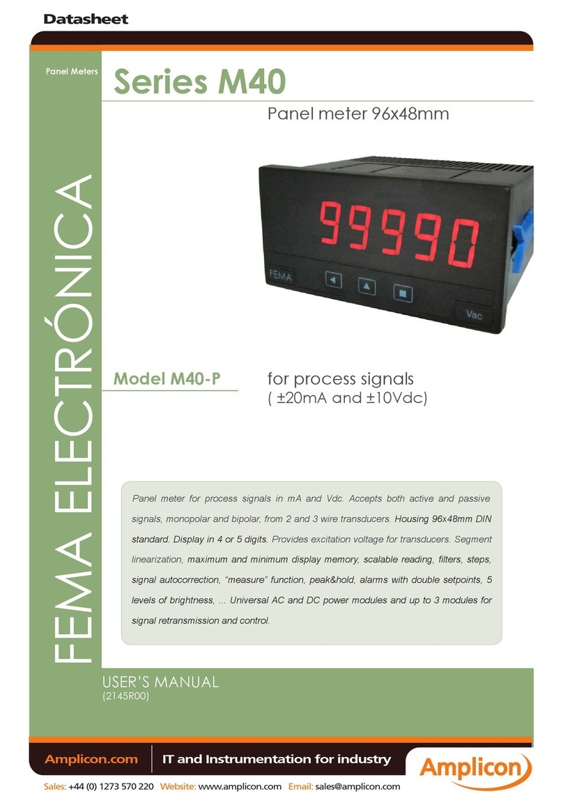
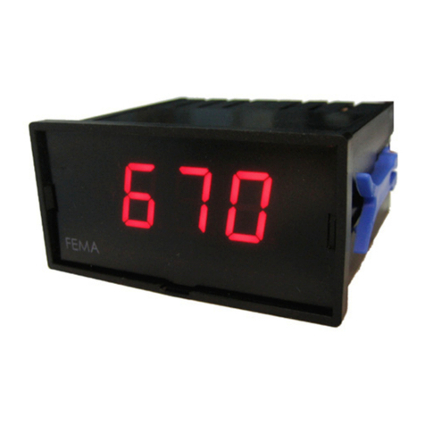
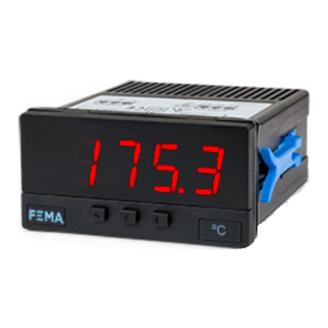
Digital panel meter, in 96 x 48 mm housing (1/8 DIN standard). Accepts 4/20 mA signals from active loops. The instrument is loop powered from the
input signal. Scalable reading with 4 digits (9999 / -1999) with congurable decimal point. Display made of 7 segment red color led for best reading.
Front protection IP50 with optional IP65. Connections with plug-in screw terminals.
Congurable fast access menu at front key ‘UP’ (5) to maximum and minimum memories, and ‘measure’ function. ‘Square root’ function to work with
differential pressure ow meters. ‘Field correction’ function and several display lters to tune reading stability. Conguration with simplied scaling,
‘password’ function to block access to the conguration menu.
Designed for industrial use, with potential integration into a wide range of applications, reduced cost, excellent quality and optional customization
of the instrument.
1. Material included . . . . . . . . . . . . . . . . . . . . . . . 2
2. Installation and start-up . . . . . . . . . . . . . . . . . . . . 2
3. How to order . . . . . . . . . . . . . . . . . . . . . . . . . . 2
4. Additional information. . . . . . . . . . . . . . . . . . . . . 2
5. Front and rear view . . . . . . . . . . . . . . . . . . . . . . 3
6. Input signal connections. . . . . . . . . . . . . . . . . . . . 3
7. Functions included. . . . . . . . . . . . . . . . . . . . . . . 3
8. Simplied scaling . . . . . . . . . . . . . . . . . . . . . . . 3
9. Conguration system . . . . . . . . . . . . . . . . . . . . . 4
10. ‘Normal mode’ of operation . . . . . . . . . . . . . . . . . 4
11. How to operate the ‘Conguration menu’ . . . . . . . . . . 4
12. How to operate the ‘Fast access’ menu . . . . . . . . . . . 5
13. Conguration menu. . . . . . . . . . . . . . . . . . . . . . 6
13.1 Scaling 6
13.2 Field correction 6
13.3 Display 6
13.4 Key UP (fast access) 7
13.5 ‘Tools’ menu 7
14. Technical specications . . . . . . . . . . . . . . . . . . . 8
15. Error codes . . . . . . . . . . . . . . . . . . . . . . . . . . 8
16. Mechanical dimensions (mm / inch) . . . . . . . . . . . . . 8
17. Precautions on installation. . . . . . . . . . . . . . . . . . 9
18. Warranty . . . . . . . . . . . . . . . . . . . . . . . . . . . 9
19. Factory default parameters . . . . . . . . . . . . . . . . . 9
20. CE declaration of conformity. . . . . . . . . . . . . . . . . 9
21. Application examples. . . . . . . . . . . . . . . . . . . . .10
22. Options and accessories . . . . . . . . . . . . . . . . . . .10
22.1 Other options 10
22.2 Accessories 11
INDEX
USER’S MANUAL
The instrument is provided with the following elements:
• 1 x instrument LP4
• 1 x plug-in screw terminals
• 1 x quick installation guide
• 1 x set of units labels
1. Material included
If this is the rst time you are conguring this instrument, below
are the steps to follow to install and congure the instrument.
Read all the manual sections in order to have a full and clear view of the
characteristics of the instrument. Do not forget to read the installation
precautions at section 17.
1. Connect the input signal (see section 6). The instrument display will
light as soon as the input signal loop is active.
2. To congure the reading, access the ‘conguration menu’ (see section 13.1).
3. If needed, block access to the ‘conguration menu’ (see section 13.5)
2. Installation and start-up
User’s Manual www.fema.es/docs/5137_LP4_manual_en.pdf
Datasheet www.fema.es/docs/5139_LP4_datasheet_en.pdf
Quick installation guide www.fema.es/docs/5142_LP4_installation_en.pdf
CE declaration www.fema.es/docs/5140_CE-Declaration_LP4_en.pdf
Warranty www.fema.es/docs/4153_Warranty1_en.pdf
Web www.fema.es/Series_LP4
LP4
Model Customization
.XXXX (customized execution)
Options
-NBT (no front keypad)
-65 (front IP65)
-(empty)
3. How to order
4. Additional information

Model LP4
SERIES SPECIAL . LOOP POWERED METERS
www.fema.es 3
The instrument needs 2 points to scale the reading, as they dene a
straight line at the ‘input vs reading’ graph. By default, the instrument is
scaled with a 4/20 mA = 0/9000 conguration. The 2 points are indicated
at the graph below (see Table 3).
The usual scaling only needs to congure the ‘display low’ and ‘display
high’ parameters (see section 13.1). The ‘input low’ and the ‘input high’
parameters can still be directly accessed from the ‘tools’ menu (see
section 13.5) or from the ‘eld correction’ function (see section 13.2).
Table 1 | INPUT signal connections
INPUT
signal
Input terminals Connections
123
4/20 mA
active
mA+
(in)
not
connected
mA-
(out)
123
mA-
mA+
5. Front and rear view
Key ‘UP’Key ‘SQ’Key ‘LE’
‘Conguration menu’
(see section 11)
‘Fast access‘
(see section 12)
UnitsLogo
Input signal
(see section 6)
123
Detail of the plug-in screw terminals provided with the
instrument. The instrument is provided with all terminals
needed, both male and female.
The instrument is ‘loop powered’ and needs a minimum current
at the input signal to operate (see section 14).
Connect the input signal to terminals 1 ‘current input’ and 3
‘current output’ (see Table 1).
The instrument is protected against inverted connections. Inverted
connections will not damage the instrument, the loop will remain open
and the instrument does not operate (display does not light).
Terminal 2 is not connected. Connecting any of the wires to terminal
2 will not damage the instrument, the loop will remain open and the
instrument will not operate (display will not light).
6. Input signal connections
7. Functions included
Table 2 |Functions included
Function Description Section
Square root
Apply a square root to the reading, for
example when working with differential
pressure ow meters. 13.3
Fast access
Use front key ‘UP’ (5) to have a fast
access to memory of maximum and
minimum, and to ‘measure’ function.
13.4
Field correction Apply the actual input signal to the ‘display
low’ or ‘display high’ parameter. 13.2
Measure
Visualize the actual signal at the input,
directly in milliamperes, without scaling,
for example for troubleshooting purposes. 13.4
Memory of max. and
min.
Visualize the memory of maximum and
minimum reading since the last reset. 13.4
Simplied scaling
Simplied scaling, only with ‘display low’
and ‘display high’ parameters. Access to
‘input high’ and ‘input low’ is still available
at the ‘tools’ section.
13.1
Password Block access to the conguration menu, to
non authorized operators. 13.5
8. Simplied scaling
Table 3 | INPUT VERSUS READING (4/20 mA = 0/9000)
Reading
0.0 Input
4 mA 20 mA
9000
Point 1
Point 2
‘input low’ = 4 mA ‘display low’ = 0.0
‘input high’ = 20 mA ‘display high’ = 9000

FEMA
·
MANUFACTURING FOR INDUSTRIAL AUTOMATION
4
9. Conguration system
CONFIGURATION SYSTEM
The LP4 loop powered process meter is fully congurable from the
instrument front panel, through a conguration system made of three
push button keypad and the four red digit led display (see Table 4).
AT POWER-UP
When the input signal loop is connected, the instrument applies the
following sequence:
• the ‘display’ shows the rmware version ‘A7.xx’
• the ‘display’ shows the message ‘mA’
• the instrument measures the input signal, applies the congured
scaling, and shows the value on display. The instrument is now in
‘normal mode’ of operation.
FROM ‘NORMAL MODE’ OF OPERATION
From ‘normal mode’ of operation, the operator can access the following
functions:
• key ‘SQ’ (<) gives access to the ‘conguration menu’ (see section 11)
• key ‘UP’ (5) gives access to the ‘fast access’ menu (see section 12)
10. ‘Normal mode’ of operation
HOW TO ENTER THE ‘CONFIGURATION MENU’
With the instrument in ‘normal mode’ of operation (see section 10), press
the ‘SQ’ (<) key and maintain for 1 second. The horizontal leds light
from bottom to top. When the upper led lights, the instrument enters into
the ‘conguration menu’.
If the ‘SQ’ (<) key is released before entering into the
‘conguration menu’, the horizontal leds light downwards from
top to bottom, and the instrument returns to ‘normal mode’ of
operation.
HOW TO OPERATE INSIDE THE ‘CONFIGURATION MENU’
Inside the ‘conguration menu’, use the front keypad to move through
menu entries, parameters, and select conguration values:
•Key ‘SQ’ (<) functions as the ‘ENTER’ key. It selects the menu entry
currently displayed. At numerical value entries, it validates the number
displayed.
•Key ‘UP’ (5) moves vertically through the different menu entries. At
numerical value entries, it modies the selected digit by increasing its
value to 0, 1, 2, 3, 4, 5, 6, 7, 8, 9.
•Key ‘LE’ (3) functions as the ‘ESCAPE’ key. It leaves the selected
menu entry (discarding changes), and eventually, will leave the
‘conguration menu’ (storing changes validated with the ‘SQ’ (<)
key). When leaving the ‘conguration menu’, the changed parameters
are stored, the instrument is restarted, and the new conguration is
activated. At numerical value entries, the ‘LE’ (3) key allows to select
the active digit. To modify a numeric value press the ‘LE’ (3) key
to select the digit to modify, select the ‘UP’ (5) key to increase the
value ‘+1’, and when all digits are modied, press the ‘SQ’ (<) key to
validate the new value.
11. How to operate the ‘Conguration menu’
Table 4 | CONFIGURATION SYSTEM
Display
Key ‘SQ’ (<)
Key ‘UP’ (5)
Key ‘LE’ (3)
Table 5 | Example of how to operate inside the ‘Conguration menu’
Scaling
1. The ‘SQ’ (<) key enters into the
‘conguration menu’.
2. The ‘SQ’ (<) key enters into the
‘ScAL’ menu.
3. The ‘UP’ (5) key moves through
the menu options.
4. The ‘SQ’ (<) key selects the
value and returns to the ‘ScAL’
menu.
5. The ‘LE’ (3) key leaves the
actual menu level and moves to
the previous menu level.
6. The ‘LE’ (3) key leaves the
‘conguration menu’. Changes are
applied and saved at this moment.
(2)
(3)
(3)
(3)
(3)
(4)
(4)
(4)
(4)
(5)
(5)
(5)
(3)
(3)
(6)
(6)
(1)
Note: example indicated above is for information purposes only, and may not
match with the actual menu entries of the instrument.

Model LP4
SERIES SPECIAL . LOOP POWERED METERS
www.fema.es 5
HOW TO ENTER THE ‘FAST ACCESS’ MENU
With the instrument in ‘normal mode’ of operation (see section 10), press
the ‘UP’ (5) key. The instrument enters into the ‘fast access’ menu.
HOW TO OPERATE INSIDE THE ‘FAST ACCESS’ MENU
The available functions inside the ‘fast access’ menu can be congured
(see section 13.4). By default, ‘memory of maximum’, ‘memory of
minimum’ and ‘measure function’ are available. See section 13.4 for a list
of congurable functions.
• press the ‘UP’ (5) key to move to the next function.
• press the ‘SQ’ (<) key to activate the selected function.
When the function is active, the display remains ashing. Press any key
to deactivate the function (display stops ashing).
‘ROLLBACK’ FUNCTION
If there is no interaction from the operator for 30 seconds, the
instrument exits the ‘fast access’ menu and returns to ‘normal
mode’ of operation.
HOW TO EXIT ‘FAST ACCESS’ MENU
To exit the ‘fast access’ menu, press the ‘LE’ (3) key, or press the key
‘UP’ (5) key until the parameter ‘- - - -’ appears, and select by pressing
the ‘SQ’ (<) key, or wait without pressing any key until the automatic
‘rollback’ activates.
When exiting the ‘fast access’ menu, the instrument returns to ‘normal
mode’ of operation.
12. How to operate the ‘Fast access’ menu
Table 6 | Example of ‘Fast access’ menu with all functions set to ‘on’
‘Memory of max.’
‘Memory of min.’
Exit
Measured value
See section 13.4 for a list and a description of available functions.
HOW TO EXIT THE ‘CONFIGURATION MENU’
When exiting the ‘conguration menu’ without changes (either by
‘rollback’ activation or because there are no changes in the conguration),
the horizontal leds light down from top to bottom, and the instrument
returns to ‘normal mode’ of operation.
When exiting the ‘conguration menu’ with changes, the display leds light
a round shape while the new conguration is stored. When the round
shape is nished, the horizontal leds light down from top to bottom and
the instrument restarts with the new conguration. The instrument is
now in ‘normal mode’ of operation.
‘ROLLBACK’ FUNCTION
If there is no interaction from the operator for 30 seconds, the instrument
exits the ‘conguration menu’ discarding changes, and returns to ‘normal
mode’ of operation.

FEMA
·
MANUFACTURING FOR INDUSTRIAL AUTOMATION
6
13. Conguration menu
13.1 Scaling
At the ‘Scaling’ (ScAL) menu entry, congure the display reading. See
section 8 for a detail on the 2 points associated to scaling.
• at the ‘Decimal point’ (‘dP’) parameter congure the position for the
decimal point. Use key ‘LE’ (3) to move the decimal point position.
Press key ‘SQ’ (<) to validate.
• at the ‘Display low’ (‘d.Lo’) parameter congure the reading
associated to an input signal low of 4 mA. Input signal low can be
modied by using the ‘eld correction’ function (see section 13.2) or by
direct conguration of ‘input low’ parameter (see section 13.5).
• at the ‘Display high’ (‘d.hI’) parameter congure the reading
associated to an input signal high of 20 mA. Input signal high can be
modied by using the ‘eld correction’ function (see section 13.2) or by
direct conguration of ‘input high’ parameter (see section 13.5).
0 to 100
Scaling Decimal point
Display low
Display high
Field correction Correction low
Correction high
Wait for 3 seconds
Wait for 3 seconds
13.2 Field correction
At the ‘Field correction’ (F.cor) menu entry, access the ‘eld correction’
functions. Use the ‘eld correction’ functions to associate the actual
input signal at terminals, to the ‘display low’ or ‘display high’ display
values. See section 8 for a detail on the 2 points associated to scaling.
• at ‘Correction low’ (F.Lo) press key ‘SQ’ (<) to activate the function.
The display reads ‘wait’ while performs the reading of the actual input
signal value and associates this value to the ‘input low’ parameter.
When nished, the instrument goes back to the ‘Correction low’ (F.Lo)
menu entry.
• at ‘Correction high’ (F.hI) press key ‘SQ’ (<) to activate the function.
The display reads ‘wait’ while performs the reading of the actual input
signal value and associates this value to the ‘input high’ parameter.
When nished, the instrument goes back to the ‘Correction high’ (F.hI)
menu entry.
Display
Square root
Average lter
Steps
Left zeros
Memory of max.
Memory of min.
13.3 Display
The ‘Display’ (dISP) menu entry groups conguration parameters
associated to the display.
• activate the ‘Square root’ (Sq.rt) parameter to ‘on’ to apply a ‘square
root’ function to the reading. The instrument reads the input signal
value in milliamperes, and scales the reading as congured at the
‘scaling’ section. Then applies the ‘square root’ function to the scaled
value. The last action applies the lter values (‘average’, ‘steps’, etc)
and reads the nal value on display. The ‘square root’ function is to be
applied when working with differential pressure ow meters.
• the ‘Average lter’ (AVr) applies a recursive lter upon the reading
values, in order to reduce oscillations due to noisy signals. Congure
the lter strength between ‘0’ and ‘100’. The lter is stronger with
higher values. Value ‘0’ disables the lter. Increasing the strength of
the lter slows the reading.
• the ‘Steps’ (StEP) function congures the reading to be done in steps
of 1, 2, 5, 10, 20 or 50 counts.
• the ‘Left zeros’ (LZEr) parameter activates the reading with active
left zeros.

Model LP4
SERIES SPECIAL . LOOP POWERED METERS
www.fema.es 7
13 Conguration menu (cont.)
• the ‘Memory of maximum’ (MAX) displays the maximum reading
stored on memory. To reset this memory, select the ‘rSt’ input. The
value can be accessed through the ‘fast access’ menu at front key ‘UP’
(5) (see section 13.4).
• the ‘Memory of minimum’ (MIn) displays the minimum reading
stored on memory. To reset this memory, select the ‘rSt’ input. The
value can be accessed through the ‘fast access’ menu at front key ‘UP’
(5) (see section 13.4).
Key ‘UP’
(fast access)
Memory of max.
Memory of min.
Measure function
Tools Input range
Version
Input low
Input high
Password
Factory reset
13.4 Key UP (fast access)
The key ‘UP’ (5) at the front of the instrument gives access to a
congurable list of functions. See section 12 for information on how to
operate the ‘fast access’ menu.
At the ‘Key UP (fast access)’ (K.uP) menu select which functions will be
available when pressing the front key ‘UP’ (5). Select ‘on’ to activate the
desired functions.
• Select ‘Memory of max.’ (MAX) to activate access to the memory of
maximum value, and reset function.
• Select ‘Memory of min.’ (MIn) to activate access to the memory of
minimum value, and reset function.
• Select ‘Measure function’ (MEAS) to activate an access to visualize
the actual input signal value, in milliamperes, without the scaling.
13.5 ‘Tools’ menu
The ‘Tools’ (tool) menu groups several functions.
• at the ‘
Input range
’ (
InP.r
) menu entry, manually congure the ‘input
low’ and the ‘input high’ values. These values are by default set to ‘4.00’
and ‘20.00’ milliamperes, and are associated to the ‘display low’ and
‘display high’ parameters. See section 8 for a detail on the 2 points
associated to scaling.
• at ‘
Brightness
’ (
LIGh
) select ‘uniform’ for a constant brightness,
independent of the input signal. Select ‘adaptive’ to get higher
brightness when input signal is higher than 6 mA (aprox.).
• the ‘
Version
’ (
VEr
) parameter informs about the rmware version
running in the instrument.
• at the ‘
Password
’ (
PASS
) parameter dene a 4 digit code to block
access to the ‘conguration menu’. Activate the password to prevent
access to the instrument conguration by non authorized personnel.
To activate the ‘Password’ function, enter the code and validate. The
password will be requested when entering the ‘conguration menu’.
The password does not block access to the ‘fast access’ menu. To
deactivate the password, set the password value to ‘0000’.
• at the ‘
Factory reset
’ (
FAct
) parameter select ‘yes’ to activate the
default factory conguration (see section 19 for a list of factory
default parameters).
Brightness Adaptive
Uniform

FEMA
·
MANUFACTURING FOR INDUSTRIAL AUTOMATION
8
14. Technical specications 15. Error codes
Table 7 | Error codes
(Blank)
No display is lightning.
The input current is lower than 2.0 mA or input signal connections
is inverted.
‘Lo’ The input current is lower than 3.8 mA.
‘h.oVr’ ‘Hardware overrange’.
Input signal is above the maximum readable signal (+22 mA).
‘Err.3’
‘Password error’.
If ‘password’ function is active, the password code entered is not
correct.
In case of error, the error code is shown ashing on display. The error
codes are not visible while on ‘conguration mode’ or in ‘fast access’
menu.
The error code remains active on display until the problem that caused
the error is solved. In case of multiple error codes, solve the rst problem
to see the next active error code.
DIGITS AND READING
number of digits 4
type 7 segment led
color red
digit height 14 mm
maximum reading 9999
minimum reading -1999
decimal point congurable X.X.X.X.
overrange / underrange ash on display
display refresh 2 times / second
acquisition per second 2 acquisitions / second
memory retention values for maximum and minimum reading are
stored every 10 minutes
INPUT SIGNAL
signals accepted 4/20 mA (2 wire)
maximum oversignal 30 mA (signals above this value may destroy
the input circuit)
accuracy ±0.1 % F.S. (±1 count)
thermal drift <150 ppm / ºC
step response 1500 mSec. (0 % to 99 % signal)
POWER SUPPLY
type loop powered from the input signal
minimum current to power-up
3.8 mA
voltage drop at terminals <11 Vdc
wires 0.5 mm2 to 2.0 mm2 (AWG20 to AWG14)
CONFIGURATION
front keypad 3 push buttons
MECHANICAL
mounting panel mount
IP front protection IP50 standard (IP65 optional)
IK impact protection IK06
connections plug-in screw terminals (pitch 5.08 mm)
housing material ABS, polycarbonate (V2)
weight <110 grams
front size 96 x 48 mm (1/8 DIN standard)
panel cut-out 92 x 44 mm
deep 91 mm including terminals
TEMPERATURE
operation from 0 to +50 ºC
storage from -20 to +70 ºC
‘warm-up’ time 15 minutes
PACKAGING
size 116 x 114 x 50 mm
material cardboard
weight <150 grams
16. Mechanical dimensions (mm / inch)
Panel
cut-out
44 mm
96 mm
48 mm
75 mm16 8
Units
(0.31)(0.63) (2.95 in.)
(1.89 in.)
(3.78 in.)
(1.74 in.)
(3.63 in.)
92 mm

Model LP4
SERIES SPECIAL . LOOP POWERED METERS
www.fema.es 9
17. Precautions on installation
This instrument is warranted against all manufacturing defects for a
period of 24 months, as requested by the European legislation. This
warranty does not apply in case of misuse or accident, and the scope
of the warranty is limited to repair of the instrument, not being the
manufacturer responsible for additional damages or additional costs.
Within the warranty period and after examination by the manufacturer,
the unit will be repaired or substituted when found to be defective.
Extended warranty available at (see section 4)
18. Warranty
Scaling
Decimal point xxxx
Display low 0
Display high 9000
Display
Square root off
Average lter 0
Steps 1
Left zeros off
Memory of maximum -1999
Memory of minimum 9999
Key ‘UP’ (fast access)
Memory of maximum on
Memory of minimum on
Measure function on
Tools
Input range
Input low 4.00 [mA]
Input high 20.00 [mA]
Brightness adaptive
Password off (0000)
This instrument has been designed and veried conforming to the
61010-1 CE Security Regulation, for industrial applications. Installation
of this instrument must be performed by qualied personnel only. This
manual contains the appropriate information for the installation. Using
the instrument in ways not specied by the manufacturer may lead to a
reduction of the specied protection level. Disconnect the instrument
from all external circuits before starting any maintenance and / or
installation action.
The instrument does not have a general switch and will start operation as
soon as signal is connected and the current is higher than the minimum
current needed.
The instrument is designed to be panel mounted. An appropriate
ventilation of the instrument must be assured. Do not expose the
instrument to excess of humidity. Maintain clean by using a humid
rag and do NOT use abrasive products such as alcohols, solvents, etc.
General recommendations for electrical installations apply, and for
proper functionality we recommend: if possible, install the instrument far
from electrical noise or magnetic eld generators such as power relays,
electrical motors, speed variators, ... If possible, do not install along the
same conduits power cables (power, motor controllers, electrovalves, ...)
together with signal and/or control cables. In case of re, disconnect
the instrument from the power line, re alarm according to local rules,
disconnect the air conditioning, attack re with carbonic snow, never
with water.
Instrument conforms to CE rules and regulations.
19. Factory default parameters
Manufacturer FEMA ELECTRÓNICA, S.A.
Altimira 14 - Pol. Ind. Santiga
E08210 - Barberà del Vallès
BARCELONA - SPAIN
www.fema.es - [email protected]
Products LP4
The manufacturer declares that the instruments indicated comply with the
directives and rules indicated below.
Electromagnetic compatibility directive 2014/30/EU
ROHS directive 2011/65/EU
WEEE directive 2012/19/EU
Security rules EN-61010-1
Instrument Fixed, Permanently connected
Pollution degree 1 and 2 (without condensation)
Electromagnetic compatibility rules EN-61326-1
EM environment
Industrial
CISPR 11 Instrument Class A, Group 1
For a detailed declaration see document 5140 at section 4.
Barberà del Vallès, September 2020
Xavier Juncà - Product Manager
According to directive 2012/19/EU, electronic equipment
must be recycled in a selective and controlled way at the
end of its useful life.
20. CE declaration of conformity

FEMA
·
MANUFACTURING FOR INDUSTRIAL AUTOMATION
10
Instruments without front keypad.
To congure the instrument,
remove the meter from the panel
and remove the front lter. Internal
press buttons for conguration
are accessible. Optionally, request
the instrument precongured from
factory. Without front keypad
O-ring for IP65 front protection
Instruments can be adapted to your needs :
• improved technical specications
• custom congurations
• special functions
• ...
21. Application examples 22. Options and accessories
Table 8 | Example of LP4 ‘loop powered meter’ placed close to the transmitter
using the existing loop to the PLC
4/20 mA
transmitter
Units
LP4 loop powered
meter
PLC
The LP4 loop powered meter can be directly inserted into the existing current
loop that connects the trasmitter and the PLC. Just cut the loop, and connect
the LP4. Place it close to the transmitter to provide instant information to the
local operator and maintenance personnel.
Table 9 | Example of LP4 ‘loop powered meter’ placed close to the transmitter
4/20 mA
transmitter
Units
LP4 loop powered
meter
Power supply
+-
The LP4 loop powered meter can be used to for local visualization of the
transmitter reading.
22.1 Other options
22.1.1 Option NBT
22.1.2 Option 65
22.1.3 Option ‘customized’

Model LP4
SERIES SPECIAL . LOOP POWERED METERS
www.fema.es 11
22.2 Accessories
Adapter for DIN rail mount, for
96 x 48 mm panel meters.
22.2.1 Adapter DRA-M
Adapter 96 x 96 mm for 96 x 48 mm
panel meters
22.2.2 Adapter KA96
Removable front cover for
additional mechanical and IP65
front protection.
22.2.3 Protector KIP
Wall mount housing. Together
with the KIP protector, offers a full
IP65 protection. For for 96 x 48 mm
panel meters.
22.2.4 WME wall housing
Benchtop housing for for 96 x 48 mm
panel meters. Handle with three
selectable positions. Power
connector with manual switch and
fuse holder.
22.2.5 THM benchtop housing
Set of labels ‘Vdc’, ‘Vac’, ‘Adc’, ‘Aac’,
‘mVdc’, ‘mVac’, ‘mAdc’, ‘mAac’, ‘%’,
‘ºC’, ‘ºF’, ‘ph’, ‘m’, ‘cm’, ‘mm’, ‘bar’, ‘psi’,
‘Pa’, N’, ‘Ω’, ‘KΩ’, ‘W’, ‘kW’, ‘MW’, ‘kV’,
‘kA’, ‘m/min’, ‘rpm’, ‘l’
(1 set included with each instrument)
22.2.6 Set of units (included)

Table of contents
Other Fema Measuring Instrument manuals