Fema M Series User manual

Series M . M60-LC
Panel meter for load cells
Digital panel meter for load cells. Provides excitaon voltage to power up to 8 cells. Standard
96 x 48 mm size (1/8 DIN). Reading with 6 digit display. Accepts 4 and 6 wire load cells, includes ‘sense’
funcon, fast access to alarm setpoints, tare and ‘auto-tare’ funcons, ‘on power up’ funcons, stabil-
ity alarms, congurable operator menu, congurable led brightness. Universal AC and DC power. Up
to 3 oponal modules for output and control (relays, transistor, control SSR, analog outputs, Modbus
RTU communicaons, RS-485 ASCII, RS-232, ...)
www.fema.es
DIGITAL PANEL METERS
4507r05
User’s Manual
ELECTRONICS FOR INDUSTRIAL AUTOMATION
PANEL METERS . SIGNAL CONVERTERS . LARGE DISPLAYS
Weight
Kg

FEMA ELECTRÓNICA . SERIES M . M60-LC
2
1. Panel meter M60-LC
Panel meter for load cells, size 96 x 48 mm (1/8 DIN)
Digital panel meter, with 96 x 48 mm (1/8 DIN) size and 6
digits with 14 mm digit height, for load cell signals. Pro-
vides excitaon voltage congurable to +5 Vdc or +10 Vdc
to power up to 8 standard 350 Ohms cells. Scalable read-
ing from 999999 to -199999 with congurable decimal
point.
Tare funcon, with congurable controls, and ‘auto-tare’
funcon for automac tare correcon when weight is re-
moved from the cell. Three working modes with dierent
acquision speeds and noise rejecon to 50 and 60 Hz.
Output and control opons with 1, 2 and 3 relays, isolated
analog outputs, Modbus RTU communicaons, transistor
outputs, SSR control outputs, RS-485 ASCII and RS-232.
Special opons up to 4 and 6 relays.
Independent alarms congurable as maximum or mini-
mum, with acvaon at setpoint or when reading is
stable, with 1 or 2 setpoints per alarm, hysteresis, inde-
pendent acvaon and deacvaon delays, congurable
inverted acvaon of the relay and congurable locked
alarms (see secon 1.12.8).
Front protecon IP65. Connecons by plug-in screw ter-
minals. For industrial applicaons.
Funcons included :
•
tare accessible from frontal key or rear contact
(see sec-
on 1.11)
• automac ‘auto-tare’ funcon (see secon 1.12.4)
• access to gross weight value and tare value (see sec-
on 1.9.5)
• funcon ‘On Power Up’ for automac acvaon of
funcons at start-up (see secon 1.12.14)
• scale factor for easy modicaon of reading units (see
secon 1.12.5)
• ‘stock units’ funcon to count units (see secon 1.12.6)
• access to the measured signal value (in mV), excitaon
current provided (in mA) and real excitaon voltage (see
secon 1.12.13)
• congurable ‘Fast access’ menu (key ‘UP’ (5)) with
access to selected funcons (see secon 1.12.13)
Mulple display lters, memory for maximum and mini-
mum, password, 5 congurable brightness levels.
1. Power and signal connecons
- connect the power (see secon 1.8)
- connect the signal (see secon 1.8)
- read recommendaons to connect the ‘sense’ (see secon
1.8.1) and for load cell ground connecons (see secon
1.8.2)
2. Inial setup (see secon 1.12.2)
- theorecal conguraon of the cell (obtain the load cell
data : sensivity, load and excitaon) and congure the
instrument
- apply the empirical conguraon of the cell (apply the
high and low ‘eld correcon’)
- assign the ‘system zero’
3. Advanced conguraon (oponal) (see secon 1.12.7)
- tare conguraon, see secons 1.11 and 1.12.4
1.1 How to use this manual
- funcon ‘stock units’ (see secon 1.12.6)
- scale factor (see secon 1.12.5)
- acquision modes (see secon 1.9.1)
4. Congure the alarms (oponal) (see secon 1.12.8)
5. Display lters (oponal) (see secon 1.12.10)
6. Congure operator controls (oponal)
- congure the rear control (see secon 1.12.11)
- congure the front key ‘LE’ (3)(see secon 1.12.12)
- congure the fast access (key ‘UP’ (5)) (see secon 1.12.13)
7. Congure other funcons (oponal)
- congure the ‘on power up’ funcon (see secon 1.12.14)
- congure the password and brightness level (see secon 1.12.17)
8. Congure the output and control opons: analog (AO) or
serial (RTU, S4, S2) (see secon 1.12.18)
If this is the rst me you are conguring this instrument,
below are the steps to follow to install and congure the in-
strument. Read all the manual secons in order to have a
full and clear view of the characteriscs of the instrument.
Do not forget to read the installaon precauons
at secon
1.19
.

FEMA ELECTRÓNICA . SERIES M . M60-LC
3
1. Panel meter M60-LC . . . . . . . . . . . . . . . . 2
1.1 How to use this manual . . . . . . . . . . . . 2
1.2 Index . . . . . . . . . . . . . . . . . . . . . . . 3
1.3 How to order . . . . . . . . . . . . . . . . . . 3
1.4 Material included . . . . . . . . . . . . . . . . 4
1.5 Addional informaon . . . . . . . . . . . . . 4
1.6 Front view . . . . . . . . . . . . . . . . . . . . 4
1.7 Rear view . . . . . . . . . . . . . . . . . . . . 4
1.8 Signal and power connecons . . . . . . . . . 5
1.8.1 Connecng the ‘sense’ . . . . . . . . . . . 5
1.8.2 Connecng the cell to the ground . . . . . 5
1.8.3 Real cases . . . . . . . . . . . . . . . . . . 5
1.9 Technical specicaons. . . . . . . . . . . . . 6
1.9.1 Acquision modes. . . . . . . . . . . . . . 6
1.9.2 Signal ranges . . . . . . . . . . . . . . . . . 7
1.9.3 Number and type of cells accepted . . . . 7
1.9.4 Mechanical dimensions (mm (in)). . . . . 7
1.9.5 Gross weight, net and tare . . . . . . . . . 7
1.10 Included funcons. . . . . . . . . . . . . . . 8
1.11 ‘Tare’ funcons included . . . . . . . . . . . 8
1.12 Conguraon . . . . . . . . . . . . . . . . . 9
1.12.1 How to operate the menus . . . . . . . . 9
1.12.2 Inial set-up . . . . . . . . . . . . . . . .10
1.12.3 Inial setup menu . . . . . . . . . . . . .11
1.12.4 Funcon ‘auto-tare’ . . . . . . . . . . . .12
1.12.5 Scale factor . . . . . . . . . . . . . . . . .12
1.12.6 Funcon ‘stock’. . . . . . . . . . . . . . .12
1.12.7 Advanced conguraon menu . . . . . .13
1.12.8 Alarms. . . . . . . . . . . . . . . . . . . .14
1.12.9 Alarm conguraon . . . . . . . . . . . .15
1.12.10 Display lters . . . . . . . . . . . . . . .16
1.12.11 Rear controls . . . . . . . . . . . . . . .17
1.12.12 Front key ‘LE’ (3). . . . . . . . . . . . .17
1.12.13 Fast access. . . . . . . . . . . . . . . . .18
1.12.14 ‘On power up’ funcon. . . . . . . . . .18
1.12.15 ‘Fast access’ conguraon menu . . . .19
1.2 Index
1.12.16 ‘On power up’ conguraon. . . . . . .19
1.12.17 Tools . . . . . . . . . . . . . . . . . . . .20
1.12.18 Access to opons conguraons menu 20
1.13 Full conguraon menu. . . . . . . . . . . .22
1.14 Factory conguraon . . . . . . . . . . . . .25
1.15 Messages and errors . . . . . . . . . . . . .25
1.16 Praccal cases . . . . . . . . . . . . . . . . .26
1.16.1 Normal case . . . . . . . . . . . . . . . .26
1.16.2 Load cell with external power. . . . . . .26
1.16.3 Connecons with a juncon box . . . . .26
1.16.4 Connecons with 3 or 4 load cells . . . .27
1.16.5 Measuring mV at the laboratory . . . . .27
1.17 To access the instrument . . . . . . . . . . .28
1.18 Modular architecture . . . . . . . . . . . . .28
1.19 Precauons on installaon . . . . . . . . . .29
1.20 Warranty . . . . . . . . . . . . . . . . . . . .29
1.21 CE declaraon of conformity . . . . . . . . .29
2. Output and control modules . . . . . . . . . . .30
2.1 Module R1 . . . . . . . . . . . . . . . . . . . .30
2.2 Module T1 . . . . . . . . . . . . . . . . . . . .30
2.3 Module SSR . . . . . . . . . . . . . . . . . . .31
2.4 Module AO . . . . . . . . . . . . . . . . . . .31
2.5 Module RTU . . . . . . . . . . . . . . . . . . .32
2.6 Module S4 . . . . . . . . . . . . . . . . . . . .32
2.7 Module S2 . . . . . . . . . . . . . . . . . . . .33
2.8 Modules R2, R4, R6 . . . . . . . . . . . . . . .33
3. Other opons . . . . . . . . . . . . . . . . . . . .34
3.1 Opon NBT . . . . . . . . . . . . . . . . . . .34
3.2 Opon G . . . . . . . . . . . . . . . . . . . . .34
4. Accessories . . . . . . . . . . . . . . . . . . . . .35
4.1 THM benchtop housing. . . . . . . . . . . . .35
4.2 Adapter DRA-M . . . . . . . . . . . . . . . . .35
4.3 Adapter KA96 . . . . . . . . . . . . . . . . . .35
4.4 WME wall housing . . . . . . . . . . . . . . .35
4.5 Protector KIP . . . . . . . . . . . . . . . . . .35
M60 LC
Model Power
-
Opon 1 Others
H
- - -
Opon 2
-
Opon 3
-
-H (85-265 Vac/dc)
-L (11/60 Vdc,
24 Vac, 48 Vac)
-R1 (1 relay)
-AO (analog output)
-RTU (Modbus RTU)
-S4 (RS-485)
-S2 (RS-232)
-T1 (1 transistor)
-SSR (1 SSR control)
-(empty)
-NBT (no buons)
-G (green led)
-(empty)
1.3 How to order

FEMA ELECTRÓNICA . SERIES M . M60-LC
4
Signal
(see secon 1.8)
Opon 1 Opon 2Opon 3
Power
(see secon 1.8)
1234567 890
Front leds ‘A’ and ‘B’ show the acve funcon (see Table 1).
See secon 1.9.5 for a denion on gross weight, net weight
and tare. The manual acvaon of the ‘tare’ acvates a fast
ash on led ‘B’.
1.4 Material included
The shipment includes :
- 1 instrument M60-LC
- 1 pack of orange power terminals
- 1 pack of green signal terminals
- 1 user’s manual
- 1 set of units label (see Figure 1)
If the instrument mounts output and control opons (see
secon 2), the shipment also includes:
- 1 pack of green signal terminals for each output and con-
trol opon installed
Figure 1 - Set of units label
1.5 Addional informaon
User’s manual
• www.fema.es/docs/4507_M60-LC_manual_en.pdf
Datasheet
• www.fema.es/docs/4509_M60-LC_datasheet_en.pdf
Declaraon CE
• see secon 1.21
Warranty
• www.fema.es/docs/4153_Warranty1_en.pdf
Web
• www.fema.es/Series_M
1.6 Front view
1.7 Rear view
Reading A B
Gross weight on o
Actual tare value o on
‘tare’ funcon acvated o fast ash
Net weight o o
Units (‘stock units’)
on on
Table 1 - Meaning for the front leds ‘A’ and ‘B’
Key ‘UP’
Alarms and ‘A’,‘B’ leds
Units
Key ‘SQ’
‘Conguraon menu’
(see secon 1.12)
‘Fast access‘
(see secon 1.12.13)
Key ‘LE’

FEMA ELECTRÓNICA . SERIES M . M60-LC
5
1.8 Signal and power connecons
Vexc+
Signal+
Signal-
Sense-
Vexc-
1234567
Sense+
EK
7EK ‘on / o’ rear control
(short circuit to ‘Vexc-’)
6Vexc+ Excitaon voltage +
5Sense+ Excitaon voltage sense +
4Signal+ Signal +
3Signal- Signal -
2Sense- Excitaon voltage sense -
1Vexc- Excitaon voltage -
Figure 2 - Signal connecons
1.8.1 Connecng the ‘sense’
Measuring with load cells requires a stable and accurate ex-
citaon voltage. Connecng the ‘sense +’ and ‘sense -’ termi-
nals to the load cell, provides the instrument with an accurate
value of the excitaon voltage received by the cell. Deviaons
and errors from the standard excitaon value are automa-
cally compensated by the instrument, increasing the accuracy
and reliability of the measure.
If you do not wish to use the ‘sense ’, place a shortcircuit be-
tween terminals ‘sense +’ and ‘Vexc+’, and between terminals
‘sense -’ and ‘Vexc-’.
For applicaons with mulple cells (2, 3, 4 cells or more) con-
nect the ‘sense ’ wires to the ‘electrical middle point’ of the
power wires of all the cells (see secon 1.16.4).
1.8.2 Connecng the cell to the ground
Measuring with load cells requires an electrically clean instal-
laon. When connecng the ground to the cell system, assure
that :
• the cell connecon to ground is performed in such a way
that the current to ground DOES NOT ow through the cell.
890
8Neutral AC / Negave DC
9Not connected
0Phase AC / Posive DC
Figure 3 - Power connecons
1234567
Vexc+
Signal+ Signal-
Sense-
Vexc-
Sense+
EK
Figure 4 - Example for connecons with 1 load cell.
!
The ‘sense’ terminals must be always connected.
If you do not use the ‘sense’, shortcircuit with
‘Vexc’ terminals (see secon 1.8.1).
!
Fuse : to comply with the security regulaon 61010-
1, add to the power line a protecon fuse acng as
a disconnecon element, easily accessible to the op-
erator and idened as a protecon device.
• Power ‘H’ 250 mA me-lag fuse
• Power ‘L’ 400 mA me-lag fuse
1.8.3 Real cases
See secon 1.16 for dierent examples on how to con-
nect the load cell and congure the instrument.

FEMA ELECTRÓNICA . SERIES M . M60-LC
6
Digits
number of digits 6
led 7 segments
color red or green
digit height 14 mm
Reading
max. reading 999999
min. reading -199999
decimal point congurable X.X.X.X.X.X
overrange ash reading
underrange ash reading
Load cells
type of cells 1 mV/V, 2 mV/V, 3 mV/V and others
excitaon voltage congurable 5 Vdc or 10 Vdc
max. excitaon current 140 mA
Vexc. protecon against shortcircuit
(see error at secon 1.15)
max. terminals voltage 30 Vdc
number of cells* 1 to 8 load cells (power 5 Vdc)
1 to 4 load cells (power 10 Vdc)
*(values calculated for standard 350 Ohms load cells. For
cells with dierent impedance, the number is limited by the
140 mA available current)
Measure
signal ranges (see secon 1.9.2)
accuracy at 25 ºC (see secon 1.9.2)
thermal stability 50 ppm/º
input impedance 20 MOhm
acquisions / second see Table 2
(and refresh for alarms, analog outputs and bus)
display refresh see Table 2
step response see Table 2
0 % to 99 % signal
signal terminals
plug-in screw terminals (pitch 3.81 mm)
Power
power ‘H’ 85 to 265 Vac/dc
power ‘L’ 11 to 60 Vdc and 24/48 Vac
isolaon* 2500 Ve with power ‘H’
*(60 seconds) 1500 Ve with power ‘L’
consumpon <1.5 W only meter
<4.0 W meter with opons
power terminals
plug-in screw terminals (pitch 5.08 mm)
wire secon 1 to 2.5 mm2 (AWG17 to AWG14)
Conguraon front keypad with 3 keys
Front protecon IP65
Output and control opons
relay, analog, communicaons, ...
(see secon 2)
Mechanical
mounng panel
connecons plug-in screw terminal
housing ABS, polycarbonate (V0)
weight <150 gr.
front size 96 x 48 mm (1/8 DIN)
panel cut-out 92 x 44 mm
depth 91 mm (including terminals)
Temperature
operaon 0 to +50 ºC
storage 20 to +70 ºC
warm-up me 15 minutes
Acquisions / sec. Display refresh Step response
Mode standard 16 acq. / sec. 16 refresh / sec. 63 mSec.
Mode 50 Hz 50 acq. / sec. 16 refresh / sec. 20 mSec.
Mode 60 Hz 60 acq. / sec. 16 refresh / sec. 17 mSec.
Table 2 - Technical data for the congured acquision mode
The instrument works by default with a fast acquision mode
of 16 acquisions per second, with a noise rejecon opmized
for 50 and 60 Hz frequencies. Two addional faster acquision
modes are available, opmized for noise rejecon to a single
specic frequency of 50 Hz or 60 Hz.
To opmize the noise rejecon only to 50 Hz and / or increase
the acquision speed to 50 acquisions per second, congure
the ‘Mode’ (‘ModE’) parameter to ‘50.hZ’ value. This selec-
on increases the speed to 50 acquisions per second and
increases the noise rejecon to 50 Hz, although it reduces the
noise rejecon to 60 Hz. Congure the parameter value to ‘60.
hZ’ to increase to 60 acquisions per second and maximum
rejecon to 60 Hz noise, reducing the noise rejecon for 50 Hz.
To congure the mode see secon 1.12.7.
1.9 Technical specicaons
1.9.1 Acquision modes

FEMA ELECTRÓNICA . SERIES M . M60-LC
7
Signal
ranges
Accuracy Max. input
signal
0/100 mVdc 0.05% FS
30 V
0/30 mVdc 0.05% FS
0/20 mVdc 0.05% FS
0/15 mVdc 0.05% FS
0/10 mVdc 0.05% FS
0/5 mVdc 0.05% FS
Table 3 - Input signal ranges
1.9.2 Signal ranges
The instrument works with 6 internal signal ranges and
the acve range is automacally selected when the in-
strument is started. The selecon depends on the value
of the two parameters : ‘Sensivity’ (‘MV.V’) and ‘Excita-
on voltage’ (‘V.EXc’) (see secon 1.12.2)
Example : with a sensivity conguraon of 2.0000 mV/V
and a congured excitaon voltage of 10 Vdc, the instru-
ment selects the 20 mV input signal range, by calculat-
ing 2 mV/V x 10 Vdc = 20 mV.
The internal signal ranges available are shown below at
Table 3.
1.9.3 Number and type of cells accepted
The instrument accepts connecon for up to 8 standard
350 Ohms load cells. With a congured excitaon voltage
of 10 Vdc connect from 1 to 4 load cells. With a cong-
ured excitaon voltage of 5 Vdc connect from 1 to 8 load
cells. For load cells with dierent impedance, calculate
the current consumpon for each cell, and the total must
not exceed the maximum current the instrument can pro-
vide.
In case of problems with the power or the signal provided
by the load cells, the instrument provides three funcons
for troubleshoong purposes. These funcons allow to
access the signal input value (in mV), the excitaon volt-
age value at the ‘sense’ terminals (in Vdc) and the current
provided to the cells (in mA). The operator can use this
values to idenfy the cause of the problem. See secon
1.12.13 for more informaon on how to access this val-
ues in real me.
44
92
Panel
cut-out
48
1.9.4 Mechanical dimensions (mm (in))
The instrument shows the value for the net weight, and can
be congured to switch reading to gross weight and the actual
value of the tare. The relaon between them is :
• Net weight = gross weight - tare
Operator can access these values by conguring the fast ac-
cess menu (key ‘UP (5)) (see secon 1.12.13).
Reading the gross weight or tare values acvate the front leds
‘A’ and ‘B’ (see secon 1.6).
1.9.5 Gross weight, net and tare
1.9 Technical data (cont.)
96
(3.78 x 1.89 in)
(3.63 x 1.74 in)
16 8
75
(0.63 in) (2.95 in) (0.31 in)

FEMA ELECTRÓNICA . SERIES M . M60-LC
8
Included funcons Secon
Funcon tare yes 1.11
Auto-tare
automac zero tare
1.12.4
Maximum tare to prevent undesired
tare acvaons 1.12.7
Scale factor change the reading
scale
1.12.5
1.12.7
Stock of units counts units instead of
weight 1.12.6
Modes high rejecon to 50 Hz
and 60 Hz 1.9.1
Alarms
standard
stability alarms
double setpoint
acvaon delays
deacvaon delays
hysteresis
inverted relay
locked deacvaon
1.12.8
Display lters
xed digits
recursive
‘steps’
le zeros
1.12.10
Rear controls
acvate funcons from
rear terminal
1.12.11
Front key ‘LE’ (3)
acvate funcons from
key ‘LE’
(3)1.12.12
Fast access (key ‘UP’ (5))
fast access to param-
eters from front key
‘UP’
(5)
1.12.13
On power up
acvate funcons at
power up
1.12.14
Memory
maximum and minimum
1.12.13
Password
blocks access to congu-
raon menu
1.12.17
Troubleshoong func-
ons
values for input signal,
excitaon voltage and
excitaon current
1.9.3
1.12.13
Display brightness 5 levels 1.12.17
Table 4 - Funcons included
1.10 Included funcons 1.11 ‘Tare’ funcons included
Acvate the tare funcon to force the instrument to take the
actual signal as a ‘0’ weight. The tare funcon does not mod-
ify the internal calibraon of the cell, and can be acvated as
many mes as needed. The tare funcon is typically used to
set a ‘0’ reading when a xed weight has been added to the
load cell.
Example : a truck enters a loading area and is placed on a
weighing system. The instrument indicates that the weight of
the truck is 2.500 Kg. A tare is applied to the instrument, and
now the reading is 0 Kg. The truck enters the loading area
and when it leaves, it is placed on the weighing system again.
Now the reading is 1.550 Kg. This is the weight of the mate-
rial loaded on the truck. When the truck leaves the weighing
system the instrument reads -2.500 Kg. Acvate a tare again
to force a reading of 0 Kg or wait for a new truck.
The instrument accepts dierent ways to acvate the tare
funcon:
• from the rear terminal, shortcircuit the ‘EK’ terminal against
the ‘Vexc-’ terminal. Previously, congure the ‘EK’ terminal
with the tare funcon (see secon 1.12.11).
• from the front keypad, press the front key ‘LE’ (3). Previ-
ously, congure the ‘LE’ (3) key with the tare funcon (see
secon 1.12.12).
• automacally when the instrument starts. Previously, con-
gure the ‘on power up’ funcon with the tare funcon (see
secon 1.12.14).
• automacally with the ‘auto-tare’ funcon. The inherent
mechanical characteriscs of a load cell makes the ‘zero
weight’ signal a non constant value. This can be detected
by placing and removing the same weight from a load cell,
several mes. When the weight is removed, the reading is
not always ‘0’, but a random value close and around ‘0’. The
‘auto-tare’ funcon automates the acvaon of the ‘tare’
when the reading of the instrument is stable and close to ‘0’
(see secon 1.12.14).
To avoid accidental tares, the instrument provides the ‘Max.
Tare’ (‘MAX.t’) parameter. The acvaon of the ‘tare’ func-
on, either manual or automac, is not applied if the reading
is higher than the value dened in this parameter (see secon
1.12.7).
The actual tare value can be accessed from the front key ‘UP’
(5) acvang the ‘Tare’ funcon at the ‘Key UP’ menu (see
secon 1.12.15). A reset to the tare value can be applied also
from this same menu.

FEMA ELECTRÓNICA . SERIES M . M60-LC
9
The instrument has two menus accessible to the user :
‘Conguraon menu’ (key ‘SQ’) (<)
‘Fast access’ menu (key ‘UP’) (5)
Conguraon menu
The ‘conguraon menu’ modies the conguraon pa-
rameters to adapt the instrument to the applicaon needs.
To access the ‘conguraon menu’ press for 1 second the
‘SQ’ (<) key. This access can be blocked by acvang the
‘Password’ (‘PASS’) funcon. While operang the ‘congu-
raon menu’, the alarm status is ‘hold’ to the status it had
before accessing the menu, and the output and control
modules remain in ‘error’ state. When leaving the ‘congu-
raon menu’, the instrument applies a system reset, fol-
lowed by a brief disconnecon of the alarms and the out-
put and control modules. Funconality is then recovered
.
For a detailed explanaon on the ‘conguraon menu’ see
the following secons, and for a full view of the ‘congura-
on menu’ see secon
1.13.
‘Fast access’ menu
’
The ‘fast access’ menu is an operator congurable menu,
providing fast and direct access to the most usual funcons
of the instrument with a single key pad stroke. Press key
‘UP’ (5) to access this menu
.
See secon
1.12.15
for a list of selectable funcons for
the ‘fast access’ menu in this instrument. The ‘Password’
(‘PASS’) funcon does not block access to this menu. Ac-
cessing and modifying parameters in the ‘fast access’ menu
does not interfere with the normal funconality of the in-
strument, and it does not generate any system reset when
validang the changes.
Operang with the front keypad inside the menus
Key ‘SQ’ (<) - press the ‘SQ’ (<) key for 1 second to ac-
cess the ‘conguraon menu’. Inside the menu, the ‘SQ’
(<) key acts as an ‘ENTER’. It enters into the menu opon
selected, and when entering a numerical value, it validates
the number
.
Key ‘UP’ (5) - press the ‘UP’ (5) key to access the ‘fast ac-
cess’ menu. Inside the menu,the ‘UP’ (5) key sequenally
moves through the available parameters and menu entries.
When entering a numerical value, it modies the digit se-
lected by increasing its value to 0, 1, 2, 3, 4, 5, 6, 7, 8, 9
.
Key ‘LE’ (3) - press the ‘LE’ (3) key to acvate the con-
gured special funcons associated to this key. Inside the
menu, the ‘LE’ (5) acts as an ‘ESCAPE’. It leaves the select-
ed menu level and eventually, by leaving all menu levels, it
1.12 Conguraon
1.12.1 How to operate the menus
leaves from the conguraon menu. Then changes are ap-
plied and the instrument is back to normal funcon. When
entering a numerical value, it selects the acve digit, and
the value is then modied by key ‘UP’ (5).
‘
Rollback
’
Aer 30 seconds without interacon from the operator, the
instrument will rollback and leave the ‘conguraon menu’
or the ‘fast access’ menu. All changes will be discarded
.
(2)
(3)
(3)
(3)
(3)
(3)
(4)
(4)
(4)
(4)
(5)
(5)
(5)
(5)
(3)
(3)
(6)
(6)
(1)
Example of operaon inside
the ‘conguraon menu’.
1. The (<) key enters into
the ‘conguraon menu’.
2. The (<) key enters into
the ‘InP’ menu.
3. The (5) key moves
through the menu op-
ons.
4. The (<) key selects the
desired range and returns
to the ‘InP’ menu.
5. The (3) key leaves the
actual level and moves to
the previous menu level.
6. The (3) key leaves the
‘conguraon menu’.
Changes are applied and
saved at this moment.
Figure 5 - Example of operaon inside the ‘conguraon
menu’ (menu entries are given as example, and may not be the
exactly the same as the instrument menu entries).

FEMA ELECTRÓNICA . SERIES M . M60-LC
10
1.12.2 Inial set-up
Before starng to congure the instrument, idenfy the pa-
rameters of the load cell, at the manufacturers datasheet (see
Table 5). If the parameters are not know, leave the instrument
with the default values.
Load cell
parameters
Default values
Sensivity 2 mV/V
Nominal weight 1000 Kilos
Excitaon voltage 10 Vdc
Table 5 - Parameters of the load cell
For an accurate measure, the instrument needs to correctly
congure its parameters for the parcular load cell connect-
ed. The conguraon procedure has a rst theorecal step
and a second empirical step. The third and nal step will set
the ‘system zero’ of the instrument.
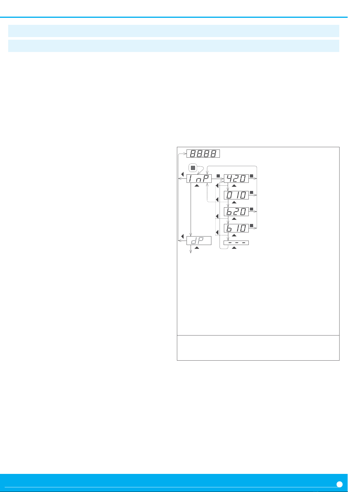
Theorecal conguraon of the load cell
The theorecal parameters are congured at the ‘Parameters
of the cell’ (‘cELL’) menu.
• at the ‘Decimal point’ (‘dP’) parameter, place the decimal
point according to the resoluon you want to see.
• at the ‘Nominal weight’ (‘LoAd’) parameter introduce the
nominal weight of the load cell. The value is entered with the
resoluon congured in the parameter above.
• at the ‘Sensivity’ (‘MV.V’) parameter, introduce the value
of the cell sensivity.
• at the ‘Excitaon voltage’ (‘V.EXc’) parameter, select 5 or
10 Vdc. (The ‘LAb’ value enables the laboratory mode, for di-
rect measure from a millivolt generator instead of a load cell
(see secon 1.16.5)).
Example : load cell with 1.95 mV/V sensivity and a nominal
value of 5 Kg and power 5 Vdc. To read in grams with a deci-
mal point, congure the theorecal parameters as indicated
below :
Decimal point : XXXXX.X
Sensivity : 1.95 mV/V
Nominal weight : 5000.0
Excitaon voltage : 5 Vdc
When the theorecal values are congured, leave the cong-
uraon menu. Apply a ‘system zero’. Force a tare, and place
dierent weights to check if the reading is correct. If it is not
correct, apply the empirical conguraon and again the ‘sys-
tem zero’.
Empirical conguraon of the load cell
The second part of the load cell conguraon is an empiri-
cal process of eld correcon. The instrument will detect and
correct the individual deviaons of this parcular load cell.
For the empirical conguraon you will need access to two
weights : a low weight, as small as possible (it can be the cell
without weight) and a high weight as close as possible to the
nominal weight of the cell.
In each case the meter will be informed of the real weight
applied to the cell in order to correct and compensate for the
measured deviaons at the signal. Both correcons are need
(high and low) for a correct conguraon of the load cell.
• low weight correcon : place the load cell without weight
or with the smallest weight possible, and access the ‘Low
weight correcon’ (‘F.Lo’) menu. Press key SQ (‘<’), intro-
duce the value of the weight and press again SQ (‘<’). The
instrument will ash shortly and return to the menu entry
‘Low weight correcon’ (‘F.Lo’).
• high weight correcon : place the load cell with a weight
closest to nominal and access the ‘High weight correcon’
(‘F.hI’) menu. Press key SQ (‘<’), introduce the value of the
weight and press again SQ (‘<’). The instrument will ash
shortly and return to the menu entry ‘High weight correc-
on’ (‘F.hI’).
Once both correcons are applied, leave the conguraon
menu. Force a tare, and place dierent weights to check that
the reading is correct. As a last step, assign the ‘system zero’ if
you want to access gross weight and net values.
Assign the ‘system zero’
This is a necessary and important step for a correct measure-
ment with a load cell.
• assign the ‘system zero’ : place the load cell without weight
or with the weight that will be considered as ‘zero’ and access
the ‘System zero’ (‘S.ZEr’) parameter. Press key SQ (‘<’). The
instrument will ash shortly and return to the menu entry
‘System zero’ (‘S.ZEr’).
The empirical conguraon of the load cell recalcu-
lates and updates the theorecal sensivity value
(‘Sensivity mV/V’ (‘M V.V’) parameter). Manual
modicaons of this parameter will modify the congura-
on of the cell. To prevent accidental modicaon con-
sider the acvaon of the ‘password’ funcon (see secon
1.12.17).
!
Once the load cell has been correctly congured,
and the reading of the instrument is correct, it is not
necessary to access again this part of the congura-
on menu. If you need to scale the reading to dierent units,
use the ‘Scale factor’ (‘ScL.F) parameters at the ‘Advanced
conguraon’ menu (see secon 1.12.7).
!

FEMA ELECTRÓNICA . SERIES M . M60-LC
11
Press ‘SQ’ (<) for 1 second to access the ‘con-
guraon menu’. For a descripon on how to op-
erate inside the menus see secon
1.12.1.
For a
full vision of the ‘conguraon menu’ structure
see secon
1.13.
At the inial set up of the instrument, rst congure the
theorecal part of the load cell at the
‘Load cell param-
eters’ (‘cELL’) menu and later congure the empirical part of
the load cell at the ‘Field correcon’ (‘F.cor’) menu.
See
sec-
on 1.12.2 for addional informaon.
• at the ‘Decimal point’ (‘dP’) parameter,
select the deci-
mal point posion. Move the decimal point with key ‘LE’
(3). The posion dened will be used for all reading pa-
rameters.
Example : to read in ‘Kg’ with tenths of kilograms, place the
decimal point at ‘XXXXX.X’ and the reading will be always
be shown with 1 decimal.
Changing the posion of the decimal point will only light a
dierent decimal point led, but will not modify or re-scale
the measure of the instrument.
• at the ‘Sensivity mV/V’ (‘MV.V’) parameter, congure the
value for the load cell sensivity. Accepts any value between
0.0001 and 99.9999 mV/V. Default value is 2.0000 mV/V.
• at the ‘Nominal weight’ (‘LoAd’) parameter, congure the
nominal weight of the load cell. accepts any value between
0 and 999999. The decimal point will be shown in the posi-
on congured at the ‘Decimal point’ (‘dP’) parameter. De-
fault value is 1000.
Example : for a 5 Kg cell, congure a value of 5000 to read
in grams.
• at the ‘Excitaon voltage’ (‘V.Exc’) parameter, congure
the voltage to power the load cell. Select ‘5 Vdc’ or ‘10 Vdc’.
Default value is 10 Vdc. Select ‘LAb’ for a millivolt meter
mode in laboratory (see secon 1.16.5).
The ‘Field correcon’ (‘F.cor’) menu includes the funcons for
the empirical conguraon of the load cell. See secon 1.12.2
for addional informaon on each funcon.
• at the ‘Low weight correcon’ (‘F.Lo’) parameter, intro-
duce the real value of the actual weight at the cell. Use the
lowest weight possible, close to 0. Press key SQ (‘<’) to
start the correcon process.
• at the ‘High weight correcon’ (‘F.hI’) introduce the real
value of the actual weight at the cell. Use the lowest weight
possible, close to nominal weight of the cell. Press key SQ
(‘<’) to start the correcon process.
The ‘System zero’ (‘S.ZEr’) entry assigns the actual weight to
the ‘system zero’ of the instrument. See secon 1.12.2 for ad-
dional informaon.
1.12.3 Inial setup menu
Load cell
parameters
Inial
conguraon
Deci
mal point
Sensivity
mV/V
Nominal weight
Excitaon
voltage 5 Vdc
10 Vdc
Field
correcon
High weight
correcon
Low weight
correcon
Low weight
value
High weight
value
System zero
Laboratory
mode

FEMA ELECTRÓNICA . SERIES M . M60-LC
12
1.12.4 Funcon ‘auto-tare’
The ‘auto-tare’ funcon automacally acvates the ‘tare’
when the weight is removed from the load cell. The ‘auto-
tare’ conguraon has three parameters :
• Acvaon value : the ‘auto-tare’ funcon acvates when
reading is lower than the dened value.
• Stability band: reading must be stable, and its uctuaon
must be lower than the number of counts dened in this pa-
rameter.
• Stability me : reading must be within the stability band for
the me dened in this parameter.
When these three parameters are met (the system is ‘without
weight’ and the reading is ‘stable’) the ‘auto-tare’ funcon au-
tomacally acvates the ‘tare’.
Example : weighing system with reading from 0.0 to 2500.0
Kg. When weight is removed from the system, there is al-
ways a variable remnant value : 2.2 Kg, 3.1 Kg, -0,7 Kg, ...
This remnant value is associated to the specic imperfecons
of each load cell. Also this remnant value takes some me to
stabilize, approximately 1 second. A manual tare can be ap-
plied each me the load cell is unloaded in order to correct
this error. The ‘auto-tare’ funcon will correct it automa-
cally without operator intervenon, conguring the follow-
ing parameters.
•acvaon value = 5.0
•stability = 1.0
•stability me = 2 seconds
When reading is lower than ‘5.0’, the ‘auto-tare’ system ac-
vates, and it will analyze the stability of the signal. When
reading does not change more than ±1.0 counts for a me of
2 seconds, the tare will automacally acvate.
The ‘auto-tare’ funcon is aected by the ‘Maximum tare’
(‘MAX.t’) parameter. The instrument will not accept the ac-
vaon of the tare when reading is higher than the ‘Maximum
tare’ (‘MAX.t’) value.
The ‘Scale factor’ (‘ScL.F’) congures a xed mulplier to ap-
ply to the reading.
Example: a weighing system is congured to read in Kg, but
the system is going to be shipped to an area where measure
must be in pounds. The relaon between kilograms and
pounds is: 1 Kg = 2,20462 pounds. Within the scale factor,
congure the mulplier to 220462 and the divider to 100000.
The instrument is now congured to read in ‘pounds’.
The ‘Stock units’ (‘Stck’) funcon is provided to count large
quanes of small units, in situaons such as stock invento-
ry, recepon of goods, etc. The operator must congure the
number of ‘units’ assigned to a weight. The instrument will
measure the weight but will show the number of ‘units’.
To congure the ‘Stock units’ funcon, weight a known num-
ber of units. Then introduce the number of units, either from
the conguraon menu (‘Advanced conguraon’ \ ‘Stock
units’) or from the fast access menu (key ‘UP’ (5)).
Example from the conguraon menu : place 50 units on the
load cell, and check that the instrument is weighing correctly.
Enter the conguraon menu, and at the ‘Stock units’ (‘Stck’)
parameter, within the ‘Advanced conguraon’, introduce
‘50’ as the number of units. Save the value (key ‘SQ’ (<))
and leave the conguraon menu (key ‘LE’ (3) two mes).
The instrument restart and reads 50 units. Add more units
and observe that the reading increases proporonally to the
number of units.
Example from the front key ‘UP’ (5) : congure the func-
on ‘Stock units’ to be accessible from the front key ‘UP’ (5)’
(fast access menu) (see secon 1.12.13) and leave the con-
guraon menu. Place 50 units on the load cell, and check
that the instrument is weighing correctly. Access the param-
eter ‘Stock units’ through the front key ‘UP’ (5), and cong-
ure the number of units actually on the load cell (50 units).
Save the value (key ‘SQ’ (<)) and leave the fast access menu
(key ‘LE’ (3)). The instrument reads 50 units. Add more units
and observe that the reading increases proporonally to the
number of units
In both cases, seng a value to the ‘Stock units’ (‘Stck’) pa-
rameter assigns the value to the actual weight. The actual val-
ue of units (‘Stock units’ (‘Stck’) parameter) can be assigned
to the actual weight by pressing front key ‘LE’ (3) (see secon
1.12.12) and/or acvang the rear terminal ‘EK’ (see secon
1.12.11).
Assign the value ‘0’ to the ‘Stock units’ (‘Stck’) parameter to
disable this funcon and return to normal reading of weight.
1.12.5 Scale factor
1.12.6 Funcon ‘stock’

FEMA ELECTRÓNICA . SERIES M . M60-LC
13
At the ‘Auto-tare’ (‘Aut.t’) menu congure the acvaon val-
ue and stability values to control the automac acvaon of
the tare, when weight is removed from the cell. See secon
1.12.4 for addional informaon.
• at the ‘Acvaon value’ (‘SEt’) parameter, congure the
working limits for the ‘auto-tare’. The ‘auto-tare’ only ac-
vates for lower values of reading. Accepts any value be-
tween 0 and 999999. Default value is 1000.
• at the ‘Stability band’ (‘bAnd’) parameter, congure the
number of counts allowed to consider a signal ‘stable’. The
‘auto-tare’ only acvates if the reading uctuates within this
band of counts. Accepts any value between 0 and 999999.
Default value is 10.
• at the ‘Stability me’ (‘tIME’) parameter, congure the
minimum me, in tenths of second, for the signal to be
within the stability band to consider it ‘stable’. Accepts any
value between ‘0.0’ and ‘99999.9’. Default value is ‘0.0’.
Value 0 at the stability band and/or 0.0 at the stability me,
disable the ‘auto-tare’ funcon.
The tare is automacally acvated when reading is lower
than the acvaon value, and the uctuaon of the reading
is lower than the counts dened at the ‘stability band’ for
the me dened at the ‘stability me’.
At the ‘Maximum tare’ (‘MAX.t’) parameter, congure the
maximum value of reading to allow for a tare to be applied.
See secon 1.12.4 for addional informaon. Accepts any val-
ue between 0 and 999999. Default value is 999999.
At the ‘Scale factor’ (‘ScL.F’) parameter, congure the value
for the mulplier and the divider. See secon 1.12.5 for addi-
onal informaon. Accepts any value between 0 and 999999.
Default value is 1.
At the ‘Stock units’ (‘Stck’) parameter, congure the number
of units for the actual weight. See secon 1.12.6 for addional
informaon. Accepts any value between 0 and 999999. De-
fault value is 0 (funcon disabled).
At the ‘Mode’ (‘ModE’) parameter, congure the acquision
mode. See secon 1.9.1 for addional informaon. Default
value is ‘Standard’ (‘Std’).
Stability me
Auto-tare
Stability band
Acvaon value
Maximum tare
Advanced conf.
Scale factor
Divider
Mulplier
Standard
Mode
60 Hz
50 Hz
Stock units Units
1.12.7 Advanced conguraon menu

FEMA ELECTRÓNICA . SERIES M . M60-LC
14
1.12.8 Alarms
The instrument manages 3 independent internal alarms, each
one controlling the acvaon of an oponal relay, transistor
or SSR control output. These outputs are oponal (see secon
2) and are installed at the free slots of the instrument (see
secon 1.18).
The instrument has three front leds that reect the state of
the three internal alarms, idened as ‘1’, ‘2’ and ‘3’. For op-
ons with 4 and 6 relay outputs, see special modules R2, R4
and R6 at secon 2.8.
• Congurable parameters
Each alarm has several conguraon parameters, starng
with the usual setpoint, hysteresis and maximum (alarm
acve when reading is higher than setpoint) or minimum
(alarm acve when reading is lower than minimum) alarm
types (see Figure 6).
• Acvaon and deacvaon delays
Each alarm can congure independent acvaon and deac-
vaon delays. These delays aect the alarm as a whole, and
the delay will aect the front led and the associated relay.
• Stability acvaon
The stability acvaon delays the alarm acvaon unl the
reading is stable (see Figure 7).
Applicaon : the lling of a tank with liquid is controlled with
a load cell. Upon reaching 5000 liters, the alarm 1 acvates to
stop the lling pump. Aer the pump has stopped, the liquid
is sll moving inside the tank, and this movement is reected
in weight and reading oscillaons. Alarm 2 is congured as
‘stability alarm’ and acvates when the liquid inside the tank
is at rest. At this moment, the tank can be removed safely.
• Second setpoint
Conguring a second setpoint creates ‘windowed alarms’.
The windowed alarm controls with a single relay output if
the reading is inside or outside the values dened (see Fig-
ure 8).
• Inverted relay
Acvate the ‘inverted relay’ funcon to invert the acvaon
logic of the associated relay.
• ‘Locked alarms’
Acvate the ‘locked alarms’ funcon to force the operator to
interact with the instrument when an alarm has acvated.
Once acvated, the alarm will remain locked at acve state,
even if the reading returns to a value below setpoint, unl
the operator manually unlocks the alarms by pressing the
front key ‘LE’ (3).
Reading
t
setpoint
hysteresis
Alarm as maximum, no
hysteresis and no delays
on
o
acvaon
delay
on
o
deacvaon
delay
Alarm as maximum, with
hysteresis and delays
on
o
Alarm as minimum
,
no
hysteresis and no delays
t
t
t
Figure 6 - Examples of alarms with 1 setpoint
Reading
t
Set points 1 and 2
Alarm 2 as maximum with
stability.
on
o
t
Alarm 1 as maximum.
on
o
t
AL1
AL2
5000
Figure 7 - Example of alarm with stability
Reading
t
Set point 2
Set point 1
Alarm as minimum, with
double setpoint, no hyster-
esis and no delays
on
o
t
Figure 8 - Example of alarm with double setpoint

FEMA ELECTRÓNICA . SERIES M . M60-LC
15
Alarm 1
Setpoint
Hysteresis
Acve
Type of alarm
Setpoint 2
Alarms
Acvaon
delay
Deacvaon
delay
Inverted relay
Locked alarm
Stability Stability band
Stability me
Alarms 1, 2 and 3 are congured from menu ‘ALr1’, ‘ALr2’ or
‘ALr3’. See secon 1.12.8 for addional informaon.
•
at the ‘Acve’ (‘Act’) parameter select ‘on’
•
at the ‘Type of alarm’ (‘TypE’) parameter, select ‘MAX’
for maximum alarm (acvates when reading is higher
than setpoint), or ‘MIn’ for minimum alarm (acvates
when reading is lower than setpoint).
•
at the ‘Setpoint’ (‘SEt’) parameter, congure the alarm
acvaon point
. Value accessible through the ‘fast access’
menu (see secon 1.12.13).
•
at the ‘Hysteresis’ (‘hySt’) parameter, select the hyster-
esis value. Hysteresis applies to the alarm deacvaon.
Alarm deacvates once the reading is beyond the set-
point plus the hysteresis value. Hysteresis prevents relay
switching in case of signal uctuaons close to the set-
point value
.
•
at the ‘Acvaon delay’ (‘dEL.0’) parameter, congure
the delay to apply before the alarm is acvated. Delay
starts to count once the setpoint is reached. Value from
0.0 to 99.9 seconds
.
•
at the ‘Deacvaon delay’ (‘dEL.1’) parameter, cong-
ure the delay to apply before the alarm is deacvated.
Delay starts to count once the setpoint is reached plus
the hysteresis value. Value from 0.0 to 99.9 seconds
.
• at the ‘Stability’ (‘StbL’)
parameter, congure the con-
dions to detect stability at the signal and acvate the
alarm. Value ‘0’ at ‘stability band’ or at ‘stability me’ de-
acvate the stability control of the alarm.
- at the ‘Stability band’ (‘bAnd’) parameter, congure the
number of counts that the reading can change and sll be
considered stable. Values from 0 to 999999. Default is 10.
-at the ‘Stability me’ (‘tIME’) parameter, congure the
me, in tenths of second, that the reading must be within
the ‘stability band’ to be considered stable.
Values from 0.0
to 99999.9. Default is 0.0.
• to work with ‘windowed alarmas’ congure ‘Setpoint 2’
(‘SEt2’) to ‘on’ and congure the value for the second set-
point. The second setpoint must always be higher than the
rst setpoint.
• at the ‘Inverted relay’ (‘r.Inv’) parameter, congure ‘on’
to invert the acvaon of the relay.
Relay is inacve when
alarm is acve, and relay is acve when alarm is inacve
.
• at the ‘Locked alarm’ (‘A.Lck’) parameter, congure ‘on’
to block the automac alarm deacvaon. Alarm deacva-
on must be performed manually, by pressing the front key
‘LE’ (3) (see secon 1.12.12) or rear control (see secon
1.12.11).
1.12.9 Alarm conguraon

FEMA ELECTRÓNICA . SERIES M . M60-LC
16
1.12.10 Display lters
The instrument provides several funcons to act upon the
reading in order to increase stability, reduce noise and adapt
to parcular needs. These funcons are grouped under the
‘Display’ (‘dISP’) menu and are explained below :
• the ‘Fixed digits’ (‘FIX.d’) funcon allows to x each digit
to a xed value. Typically, one or more right digits are xed
to ‘0’. Fix digits starng from the right. Value ‘-’ indicates that
the digit is not xed.
• the ‘Average lter’ (‘AVr’) applies a recursive lter upon
the reading values, in order to reduce oscillaons due to
noisy signals. Congure the lter strength between ‘0’ and
‘100’. The lter is stronger with higher values. Increasing the
strength of the lter slows the reading. Value ‘0’ disables the
lter.
• the ‘Steps’ (‘StEP’) funcon congures the reading to be
done in steps of 1, 2, 5, 10, 20 or 50 counts.
Example: congure a step of 20 and the reading will change
in steps of 20 counts (‘1420’, ‘1440’, ‘1460’, ...).
• the ‘Le zero’ (‘LZEr’) funcon lights all zeros to the le.
• the ‘Memory of maximum’ (‘MAX’) displays the maximum
reading stored on memory. To reset this memory,
select the
‘rSt’ input.
The value can be accessed through the ‘fast ac-
cess’ menu at front key ‘UP’ (5) (see secon 1.12.13).
• the ‘Memory of minimum’ (‘MIn’) displays the minimum
reading stored on memory. To reset this memory,
select the
‘rSt’ input.
The value can be accessed through the ‘fast ac-
cess’ menu at front key ‘UP’ (5) (see secon 1.12.13).
Le zeros
Steps
Average lter 0 to 100
Display Fixed digits Fix digits
Memory of
maximum
Memory of
minimum

FEMA ELECTRÓNICA . SERIES M . M60-LC
17
The instrument provides a digital ‘on/o’ input at the rear
terminals, referenced as ‘EK’ (see secon 1.8). Assign func-
ons to this terminal and acvate these funcons with a short
circuit between terminal ‘EK’ and terminal ‘Vexc-’. Funcons
available are explained below :
• the ‘Tare’ (‘tArE’) funcon applies a tare.
• the ‘Alarm unlock’ (‘A.LcK’) funcon unlocks all alarms
that are locked due to the ‘Locked alarms’ funcon (see sec-
on 1.12.8).
• the ‘Stock units’ (‘Stck’) funcon assigns the actual weight
to the number of units dened at the ‘stock units’ parameter
(see secon 1.12.6).
In case of mulple funcons enabled, the acvaon is per-
formed sequenally in the same order as the conguraon
menu (rst is the tare, then the alarm unlock, etc).
1.12.11 Rear controls
1.12.12 Front key ‘LE’ (3)
The front key ‘LE’ (3) can be congured to acvate a set of
funcons. Funcons available are explained below :
•the ‘Tare’ (‘tArE’) funcon applies a tare.
•the ‘Alarm unlock’ (‘A.LcK’) funcon unlocks all alarms
that are locked due to the ‘Locked alarms’ funcon (see sec-
on 1.12.8).
•the ‘Stock units’ (‘Stck’) funcon assigns the actual weight
to the number of units dened at the ‘stock units’ parameter
(see secon 1.12.6).
In case of mulple funcons enabled, the acvaon is per-
formed sequenally in the same order as the conguraon
menu (rst is the tare, then the alarm unlock, etc).
Rear controls Tare
Alarm unlock
Stock units
Key LE Tare
Alarm unlock
Stock units

FEMA ELECTRÓNICA . SERIES M . M60-LC
18
1.12.13 Fast access
The ‘fast access’ is an operator congurable menu. When
congured, the operator can access the most usual funcons
with a single press of the front key ‘UP’ (5). Funcons avail-
able are listed below :
• access to alarm setpoints from the front key ‘UP’ (5) al-
lows to read and modify the actual setpoint values
• access to the ‘stock units’ parameter from the front key
‘UP’ (5) allows to read and modify the actual ‘stock value’
parameter. See secon 1.12.6 for addional informaon
about the ‘stock units’ funcon.
• values for ‘gross weight’ and ‘tare’ are accessible from the
front key ‘UP’ (5) (see secon 1.9.5). To reset the tare value
visualize the value and press key ‘UP’ (5). When message
‘rSt’ appears, press key ‘SQ’ (<). The instrument returns
to visualize the ‘tare’ value. Press key ‘LE’ (3) to leave the
menu.
• funcons ‘signal mV’, ‘exc. voltage’ and ‘exc. current’
ve access to values for the input signal measured in mV,
the excitaon voltage measured in Vdc between terminals
‘sense+’ and ‘sense-’, and the excitaon current measured in
mA provided from the instrument to the load cell
These three funcons act as an integrated voltmeter and
ammeter, to be used for troubleshoong purposes, as they
give informaon on the real signals received and provided
to the load cell.
1.12.14 ‘On power up’ funcon
The ‘On power up’ (‘on.Pu’) menu allows to dene a series
of funcons to acvate when the instrument restarts aer a
power loss.
Funcons available are a delay on the acvaon of measure
and control funcons, and a tare funcon.
These funcons will acvate only aer a restart due to power-
loss, they will not apply aer a restart due to changes in con-
guraon.
Delay the measure and control funcons gives me to slow
system elements to start completely before the instrument
begins to acquire signal and control the outputs.
• access to maximum and minimum memories from the
front key ‘UP’ (5) allows to visualize the values. To reset the
maximum or minimum value, visualize the value, and press
key ‘UP’ (5). When message ‘rSt’ appears, press key ‘SQ’
(<). The instrument returns to visualize the actual memory
value. Press key ‘LE’ (3) to leave the menu
The ‘fast access’ menu is not aected by the password func-
on, allowing to have a locked access to the general congu-
raon menu, while sll some funcons are accessible to the
operator through the ‘fast access’ menu.
• Super fast access
If only one funcon is congured at the ‘fast access’ menu,
pressing the front key ‘UP’ (5) will shortly read the name of
the funcon and then automacally show into the value.
While on delay mode, the instrument shows all decimal points
lightened and ashing, all alarms are deacvated, and there is
no signal acquision or communicaons control. When the
delay me is over, the instrument starts its normal funcon-
ing.

FEMA ELECTRÓNICA . SERIES M . M60-LC
19
At the ‘Key UP (‘fast access’)’ (‘K.uP’) menu congure which
funcons and parameters will be accessible through the ‘fast
access’ menu. Select ‘on’ to acvate each funcon. See sec-
on 1.12.13 for addional informaon.
• the ‘Setpoint 1’ (‘ALr1’) funcon allows to visualize and
modify the setpoint for alarm 1.
• the ‘Setpoint 2’ (‘ALr2’) funcon allows to visualize and
modify the setpoint for alarm 2.
• the ‘Setpoint 3’ (‘ALr3’) funcon allows to visualize and
modify the setpoint for alarm 3.
•the ‘Stock units’ (‘Stck’) funcon allows to visualize and
modify the quanty of units dened at the ‘stock units’ pa-
rameter (see secon 1.12.6).
• the ‘Gross weight’ (‘GroS’) funcon allows to visualize the
gross weight.
• the ‘Tare value’ (‘tArE’) funcon allows to visualize the ac-
tual tare value.
• the ‘Signal mV’ (‘c.MV’) funcon allows to visualize the
actual value of the input signal, without scaling. Value is of-
fered in mV.
• the ‘Exc. voltage’ (‘c.EXc’) funcon allows to visualize the
actual value of the excitaon voltage, measured between
terminals ‘sense+’ and ‘sense-’. Value is oered in Vdc.
• the ‘Exc. current’ (‘c.MA’) funcon allows to visualize the
actual value of the current provided by the instrument to the
load cell. Value is oered in mA.
• the ‘Memory of maximum’ (‘MAX’) or ‘Memory of mini-
mum’ (‘MIn’) allows to visualize and/or reset the actual val-
ue of the maximum and minimum memory.
1.12.15 ‘Fast access’ conguraon menu
Key UP
(‘Fast access’)
Gross weight
Setpoint 1
Setpoint 2
Setpoint 3
Tare value
Stock units
Memory of
maximum
Memory of
minimum
Signal mV.
Exc. voltage
Exc. current
The ‘On power up’ (‘on.Pu’) menu assigns funcons to apply
when the instrument restarts aer a power loss. See secon
1.12.14 for addional informaon.
• at the ‘Delay’ (‘dLAy’) parameter congure the me the
instrument waits before starng normal operaon. Value be-
tween 0 and 200 seconds.
• at the ‘tare’ (‘tArE’) parameter congure to ‘on’ to acvate
a tare every me the instrument restarts aer a power loss.
1.12.16 ‘On power up’ conguraon
On power up Delay
Tare
Seconds

FEMA ELECTRÓNICA . SERIES M . M60-LC
20
1.12.17 Tools
1.12.18 Access to opons conguraons menu
Tools Password
Version
Factory
conguraon
Minimum
Brightness
Maximum
Standard
Reset
‘inial conf.’
Access to the oponal module installed at slot 1
Access to the oponal module installed at slot 2
Access to the oponal module installed at slot 3
The ‘OPt.1’, ‘OPt.2’ and ‘OPt.3’ menu entries give access to
the conguraon menus for the oponal modules installed at
Opt.1, Opt.2 and Opt.3 slots.
See secon 2 for a list of the dierent modules available that
can be installed on each slot. The conguraon menu for each
module is described at the User’s Manual of each module.
The ‘Tools’ (‘tooL’) menu groups funcons with a variety of
uses.
•at the ‘Password’ (‘PASS’) funcon dene a 6 digit code to
block access to the ‘conguraon menu’. Acvate the pass-
word to prevent access to the instrument conguraon by
non authorized personnel. To acvate the ‘Password’ func-
on select ‘on’ and enter the code.
The numerical code is asked when accessing the ‘congu-
raon menu’ (key‘SQ’ (<)). Funcons congured to be ac-
cessible through the ‘fast access’ menu are not ‘Password’
blocked.
•at the ‘Factory conguraon’ (‘FAct’) select ‘yes’ to ac-
vate the default factory conguraon (see secon 1.14 for a
list of default parameters). The cell conguraon parameters
(‘Inial conf.’ (‘Init’) menu) are not aected by this reset if
the ‘Reset ‘inial conf.’’ (‘F.InI’) parameter is ‘o’.
•at the ‘Reset ‘inial conf’’ (‘F.InI’) parameter select ‘on’ to
include the cell conguraon parameters when acvang
the default factory conguraon.
The factory reset applied to the ‘inial conguraon’
parameters aects the cell conguraon parameters.
For a correct reading, a new cell conguraon must
be applied, as indicated in secon 1.12.2.
!
•the ‘Version’ (‘VEr’) parameter informs about the rmware
version loaded on the instrument.
•At the ‘Brightness’ (‘LIGh’) parameter select the intensity
of the display brightness. Five levels available. With this
funcon the instrument brightness can be adapted to match
the brightness of nearby instruments.
Other manuals for M Series
1
This manual suits for next models
1
Table of contents
Other Fema Measuring Instrument manuals
Popular Measuring Instrument manuals by other brands

Hanna Instruments
Hanna Instruments BL 983327-0 instruction manual

LEYBOLD
LEYBOLD 531 94 instruction sheet

FMS
FMS RTM MP EMGZ482T.MP.24VDC Operation manual

Ametek
Ametek Reichert 7CR user guide

Industrial Fiber Optics
Industrial Fiber Optics IF-RL05 Operator's manual

ipf electronic
ipf electronic PT169070 instruction manual