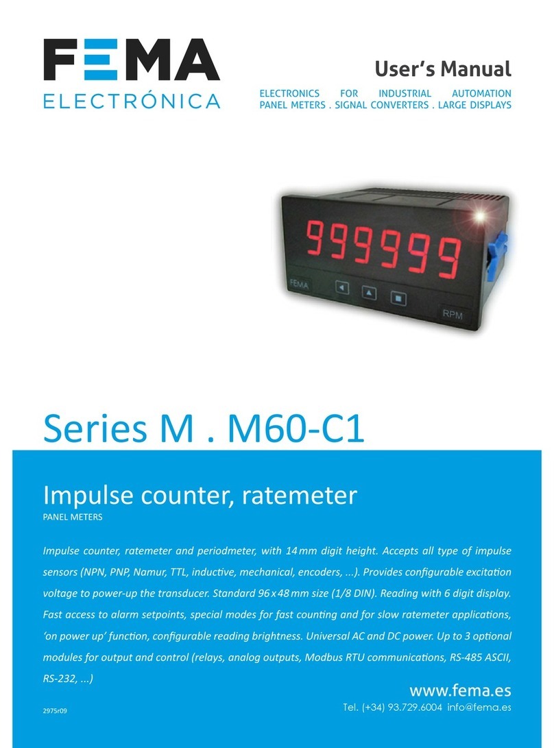
Fema C Series User manual

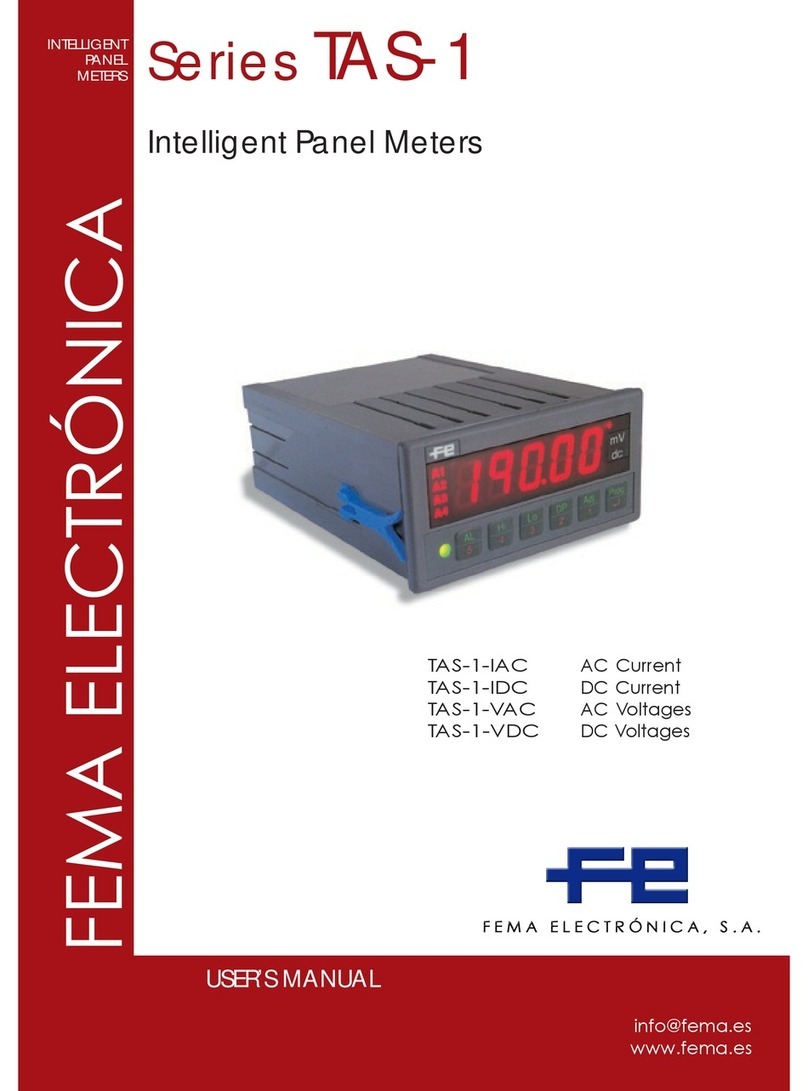
Series C . C40-D
Mulsignal panel meter
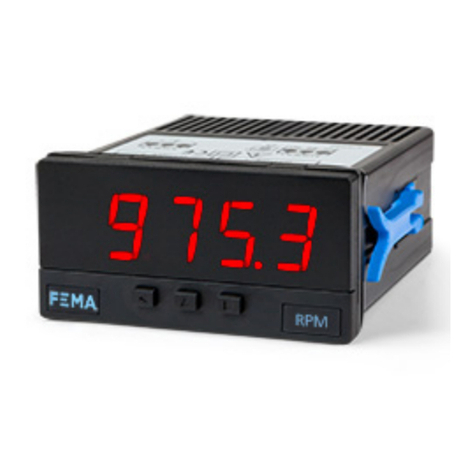
Mulsignal digital panel meter, congurable to work as AC and DC voltmeter (up to 600 Vac / dc), AC and DC
ammeter (up to 5 Aac / dc), accepts process signals (mA, Vdc), thermocouples, resisve temperature probes
(Pt, Ni, PTC and NTC), resistances, potenometers and frequency. Congurable. Standard 96 x 48 mm size
(1/8 DIN). Scalable reading with 4 digits (9999 / -1999). ‘Fast access’ funcon to alarm setpoints, ‘external
control’ to acvate predened funcons, ‘Eco’ mode for low consumpon, selectable dual scaling, 5 levels
of congurable brightness. Single universal power supply 18 to 265 Vac/dc. Oponal modules for output
and control (relays, analog output, Modbus RTU). Recommended for OEM applicaons.
www.fema.es
User’s Manual
PANEL METERS. OEM APPLICATIONS
4149r07
OEM
YOUR METER !
APPLICATIONS
ELECTRONICS FOR INDUSTRIAL AUTOMATION
PANEL METERS . SIGNAL CONVERTERS . LARGE DISPLAYS

FEMA ELECTRÓNICA . Series C . C40-D
2
1. Panel meter C40-D
Mulsignal 96 x 48 mm panel meter, for OEM applicaons
Mulsignal digital panel meter in 96 x 48 mm size (1/8 DIN), for OEM
applicaons. Accepts AC and DC voltage signals from mV up to 600 V
and currents up to 5 A (AC measures in True RMS), process signals
(mA and Vdc) with excitaon voltage included, thermocouples K, J,
E, N, L, R, S, B, T and C, resisve temperature probes (Pt100, Pt500,
Pt1000, Ni100, Ni200, Ni1000, PTC and NTC), resistances, potenom-
eters and frequency. Scalable reading with 4 digits up to 9999 / -1999
with congurable decimal point. Two independent alarms, congu-
rable as maximum or minimum, with hysteresis and setpoint.
Oponal 1 or 2 relay outputs, 4/20 mA isolated analog output, and
Modbus RTU isolated serial communicaons.
Front protecon IP50, with oponal IP65. Connecons with plug-in
screw terminals.
Index
1. Panel meter C40-D . . . . . . . . . . . . . . . . . . . . . . . 2
1.1 How to order . . . . . . . . . . . . . . . . . . . . . . . . 2
1.2 Front view . . . . . . . . . . . . . . . . . . . . . . . . . . 3
1.3 Rear view . . . . . . . . . . . . . . . . . . . . . . . . . . 3
1.4 Power connecons . . . . . . . . . . . . . . . . . . . . . 3
1.5 Signal connecons . . . . . . . . . . . . . . . . . . . . . 3
1.6 Mechanical dimensions (mm) . . . . . . . . . . . . . . . 3
1.7 Installaon and start-up . . . . . . . . . . . . . . . . . . 3
1.8 Technical specicaons . . . . . . . . . . . . . . . . . . 4
1.9 Internal jumpers . . . . . . . . . . . . . . . . . . . . . . 5
1.10 Measuring AC voltages and AC currents. . . . . . . . . 6
1.11 Measuring DC voltages and DC currents . . . . . . . . 7
1.12 Measuring thermocouples . . . . . . . . . . . . . . . . 8
1.13 Measuring with Pt and Ni probes . . . . . . . . . . . . 9
1.14 Measuring with NTC probes . . . . . . . . . . . . . . . 10
1.15 Measuring with PTC probes . . . . . . . . . . . . . . . 10
1.16 Process measures . . . . . . . . . . . . . . . . . . . . .11
1.17 Measuring frequency . . . . . . . . . . . . . . . . . . .11
1.18 Measuring resistances . . . . . . . . . . . . . . . . . . 12
1.19 Measuring potenometers. . . . . . . . . . . . . . . . 12
1.20 ‘Fast access’ menu . . . . . . . . . . . . . . . . . . . . 13
1.21 Scaling . . . . . . . . . . . . . . . . . . . . . . . . . . .13
1.22 Oset reading . . . . . . . . . . . . . . . . . . . . . . .13
1.23 ‘Eco’ mode . . . . . . . . . . . . . . . . . . . . . . . . . 13
1.24 External control . . . . . . . . . . . . . . . . . . . . . .13
1.25 Second scaling . . . . . . . . . . . . . . . . . . . . . . . 13
1.26 To open the instrument. . . . . . . . . . . . . . . . . . 14
1.27 How to operate the menus. . . . . . . . . . . . . . . . 15
1.28 Messages and errors . . . . . . . . . . . . . . . . . . . 15
1.29 Conguraon menu. . . . . . . . . . . . . . . . . . . . 16
1.29.1 Input signal ranges . . . . . . . . . . . . . . . . . . 16
1.29.2 Scaling . . . . . . . . . . . . . . . . . . . . . . . . . 17
1.29.3 Alarms . . . . . . . . . . . . . . . . . . . . . . . . . 17
1.29.4 Fast access . . . . . . . . . . . . . . . . . . . . . . .18
1.29.5 Super fast access . . . . . . . . . . . . . . . . . . . 18
1.29.6 External control . . . . . . . . . . . . . . . . . . . .18
1.29.7 Menu ‘Tools’ . . . . . . . . . . . . . . . . . . . . . .19
1.29.8 Conguring the opons. . . . . . . . . . . . . . . . 21
1.30 Full conguraon menu . . . . . . . . . . . . . . . . . 22
1.31 Precauons on installaon . . . . . . . . . . . . . . . .25
1.32 Factory conguraon . . . . . . . . . . . . . . . . . . .25
1.33 Warranty . . . . . . . . . . . . . . . . . . . . . . . . . . 25
1.34 CE declaraon of conformity . . . . . . . . . . . . . . . 25
2. Output and control modules . . . . . . . . . . . . . . . . . 26
2.1 Modules A1 and A2 (relay output) . . . . . . . . . . . . 26
2.2 Module M1 (analog output) . . . . . . . . . . . . . . . .26
2.3 Module S1 (Modbus RTU) . . . . . . . . . . . . . . . . .27
3. Other opons . . . . . . . . . . . . . . . . . . . . . . . . . .28
3.1 Opon NBT . . . . . . . . . . . . . . . . . . . . . . . . . 28
3.2 Opon 65 . . . . . . . . . . . . . . . . . . . . . . . . . .28
3.3 Opon ‘customized’ . . . . . . . . . . . . . . . . . . . . 28
4. Accessories . . . . . . . . . . . . . . . . . . . . . . . . . . .29
4.1 Adapter DRA-M . . . . . . . . . . . . . . . . . . . . . . . 29
4.2 Adapter KA96 . . . . . . . . . . . . . . . . . . . . . . . .29
4.3 Protector KIP . . . . . . . . . . . . . . . . . . . . . . . . 29
4.4 WME wall housing . . . . . . . . . . . . . . . . . . . . . 29
4.5 THM benchtop housing . . . . . . . . . . . . . . . . . . 29
4.6 Set of units (included) . . . . . . . . . . . . . . . . . . . 29
Instrument designed for industrial use, highly exible, allows for in-
tegraon in mulple applicaons, reduced cost, excellent quality and
oponal customizaon available.
• ‘Fast access’ menu at front key UP (5) congurable for fast access
to alarm setpoints (see secon 1.20).
• ‘Eco’ mode reduces power consumpon
(see secon 1.23).
• Simplied scaling conguraon (see secon 1.21).
• Funcon ‘external control’ to acvate with a contact a predened
funcon (second scaling, decimal point, reading ‘hold’, ‘tare’, memo-
ry of maximum or minimum) (see secon 1.24).
• 5 congurable brightness levels (see secon 1.29.7).
1.1 How to order
C40 D
Model Power
-
Opon 1
U - - -
-A1 (1 relay)
-M1(analog output)
-S1 (Modbus RTU)
-(empty)
-U (18-265 Vac/dc)
Others
-NBT (
no front keypad
)
-65 (front IP65)
-(empty)
-
Opon 2
-A2 (1 relay)
-(empty)
Customizaon
-XXXX (customized)
-(empty)
-
Series

FEMA ELECTRÓNICA . Series C . C40-D
3
1.2 Front view
1.4 Power connecons
1.5 Signal connecons
Key ‘UP’
Logo Units
Key ‘SQ’
Key ‘LE’
‘Conguraon menu’
(see secon 1.29)
‘Fast access‘
(see secon 1.29.4)
1.3 Rear view
Signal
(see secon 1.5)
Opon 2 Opon 1
Power
(see secon 1.4)
12345 890
Detail of the plug-in screw terminals provided with
the instrument. The instrument is provided with all
terminals needed, both male and female.
Alarm 1
Alarm 2
Earth connecon - The instru-
ment does not need earth con-
necon for correct operaon nor
for compliance with security reg-
ulaons. Terminal 9 is is not con-
nected to any internal circuit and
is provided only as a safe place
for earth wire.
Fuse - This instrument has not internal fuse. Conforming to security
regulaon 61010-1, add a protecon fuse to the power line to act as
disconnecon element, easily accessible to the operator and iden-
ed as a protecon device.
250 mA me-lag for power voltage > 50 Vac/dc
400 mA me-lag for power voltage < 50 Vac/dc
~
8 9 0
-
+
~
Power 18 to 265 Vac/dc
Signals up to 600 V and 200 V (AC and DC) must be connected at
terminals 1 and 4. Signals for 5 A current (AC and DC) must be con-
nected at terminals 3 and 4. All other signals must be connected
between terminals 2 and 4. Terminal 5 is a ‘mulfuncon’ terminal,
congurable with one of the following funcons :
• +15 Vdc excitaon voltage (Vexc) for process signals
• +5 Vdc excitaon for potenometer signals
• connecon for the Pt100 third wire compensaon
• external contact ‘EK’ funcon
To select the terminal 5 funcon, select the posion of internal jump-
er ‘T’
(see secon 1.9)
.
44
92
Panel
cut-out
16 8
75
96
48
1.6 Mechanical dimensions (mm)
HV signal
5 A {
{~Vac, ±Vdc, resistance, mA, pot,
thermocouple+, Pt+, Ni+, PTC+, NTC+
{
Signal
~600 Vac, ~200 Vac
±600 Vdc, ±200 Vdc
~5 Aac, ±5 Adc
Common {neutral, 0 V, common
12345
mulfunc.
{Vexc, Pt100 3 wire, Pot+,
‘EK’ external control
1. Open the instrument as indicated at secon 1.26 and access
the internal board.
2. Select jumpers ‘S’ for the signal range required (see secon
1.9).
3. Select jumper ‘T’ to assign to mulfuncon terminal 5 the re-
quired funconality (see secon 1.9).
4. Close the instrument ad indicated at secon 1.26.
5. Connect the input signal and the power supply as indicated at
secons 1.4 and 1.5.
6. Enter the ‘conguraon menu’ to congure the instrument
(scaling, alarms, ...) (see secon 1.29).
1.7 Installaon and start-up
Units
Units

FEMA ELECTRÓNICA . Series C . C40-D
4
Digits
number of digits 4
led 7 segments led
color red
height 14 mm
Reading
max. reading 9999
min. reading -1999
decimal point congurable X.X.X.X
readings 3 readings / second
display refresh 3 refresh / second
step response 300 mSec. (0 % to 99 % signal)
overrange reading ashes at ‘9999’
underrange reading ashes at ‘-1999’
Accepted input signals
AC voltages and currents 600 Vac, 200 Vac, 20 Vac, 2 Vac
200 mVac, 60 mVac, 5 Aac, 20 mAac
(see secon 1.10)
DC voltages and currents ±600 Vdc, ±200 Vdc, ±20 Vdc, ±2 Vdc
±200 mVdc, ±60 mVdc, ±5 Adc, ±20 mAdc
(see secon 1.11)
thermocouples K, J, E, N, L, R, S, B, T y C
(see secon 1.12)
temperature ‘Pt’ Pt100 (2 and 3 wires with automac
compensaon up to 30 R), Pt500, Pt1000
(see secon 1.13)
temperature ‘Ni’ Ni100, Ni200, Ni1000
(see secon 1.13)
temperature ‘NTC’ (see secon 1.14)
temperature ‘PTC’ (see secon 1.15)
process 4/20 mA, 0/10 Vdc (acve and passive)
(see secon 1.16)
frequency up to 100 Hz
(see secon 1.17)
resistances ranges of 5 K and 50 K
(see secon 1.18)
potenometers nominal value 500 Ohm up to 20 KOhm
(see secon 1.19)
Accuracy at 25 ºC see following secons for each signal
Thermal dri 150 ppm/º
Excitaon voltage +15 Vdc (max. 30 mA) for process signals
+5 Vdc for potenometers
(at terminal 5, see secons 1.5 and 1.16)
Power supply
power ‘U’ 18 to 265 Vac/dc
isolaon 1500 Ve.
isolaon tested for 60 sec.
AC frequency 50/60 Hz
consumpon
(without ‘Eco’)
<1.5 W meter only
<2.5 W meter with opons
consumpon
(with ‘Eco’)
<0.3 W meter only
<1.5 W meter with opons
Power wires 1 mm2 to 2.5 mm2 (AWG17 to AWG14)
Conguraon 3 front push buons
Front protecon IP50 standard
IP65 oponal (see secon 3.2)
Output opons relay, analog, serial
(see secon 2)
Mechanical
mounng panel
connecons plug-in screw terminals
housing material ABS, polycarbonate (V0)
weight <150 grams
front size 96 x 48 mm (1/8 DIN)
panel cut-out 92 x 44 mm
deep 91 mm (including terminals)
Temperature
operaon from 0 to +50 ºC
storage from -20 to +70 ºC
‘warm-up’ me 15 minutes
1.8 Technical specicaons
Funcons included Secon
Fast access to alarm setpoints, maxi-
mum and minimum
1.20
External control second scaling
decimal point 0, 1, 2 or 3
‘hold’ reading
tare funcon
memory of maximum
memory of minimum
1.24
‘Eco’ mode reduced consumpon 1.23
Alarms setpoint
hysteresis
set as max or min type
1.29.3
Oset reading subtract a xed number
of counts to reading
1.22
Display lter recursive
‘steps’
1.29.7
Simplied scaling 1.21
Memory max and min memory 1.29.4
Password blocks conguraon 1.29.7
Display brightness 5 levels 1.29.7
Table 1 - Funcons included

FEMA ELECTRÓNICA . Series C . C40-D
5
5
6
Input signal terminals
Jumpers ‘S’ for signal
range selecon
Displays
F
E
G
H
I
J
D
B
C
A
K
1.9 Internal jumpers
Internal jumpers ‘S’ are associated to the signal range. The posion
of internal jumper ‘T’ assigns the funcon of the mulfuncon termi-
nal 5. At ‘Table 2’ see a list of signal ranges and associated jumper ‘S’
and ‘T’. At Table 3 see the posion for jumper ‘T’ associated to each
funcon of the mulfuncon terminal 5. To access the internal jump-
ers, open the housing as explained at secon 1.26. For addional
informaon on each signal range see the following secons :
• Ranges for AC voltages and currents, see secon 1.10
• Ranges for DC voltages and currents, see secon 1.11
• Ranges for thermocouples, see secon 1.12
• Ranges for Pt and Ni probes, see secon 1.13
• Ranges for NTC probes, see secon 1.14
• Ranges for PTC probes, see secon 1.15
• Ranges for process signals, see secon 1.16
• Ranges for frequency signals, see secon 1.17
• Ranges for resistance measures, see secon 1.18
• Ranges for potenometer measures, see secon 1.19
Range Jumpers
‘S’
Jumper
‘T’
AC voltages and currents
~ 600 Vac G I
4-5
~ 200 Vac I
~ 20 Vac A I
~ 2 Vac B I
~ 200 mVac C I
~ 60 mVac E I
~ 5 Aac I
~ 20 mAac D I
DC voltages and currents
±600 Vdc G
4-5
±200 Vdc - - -
±20 Vdc A
±2 Vdc B
±200 mVdc C
±60 mVdc E
±5 Adc - - -
±20 mAdc D
Process
4/20 mA D
1-2*
0/10 Vdc A
* jumper 1-2 to acvate Vexc.
Select 4-5 to acvate funcon ‘EK’
Resistances
0 to 5 K F H K
4-5
0 to 50 K F K
Table 2 - Jumpers ‘S’ and ‘T’ and signal
ranges
Range Jumpers
‘S’
Jumper
‘T’
Thermocouples
Tc. K
E
4-5
Tc. J
Tc. E
Tc. N
Tc. L
Tc. R
E J
Tc. S
Tc. T
Tc. C
E
Tc. B
E J
Pt and Ni probes
Pt100
(3 wire)
F H J 5-6
Pt100
(2 wire)
F H
4-5
Pt500 F
Pt1000 F
Ni100 F H
Ni200 F H
Ni1000 F
NTC probes
NTC F K 4-5
PTC probes
KTY 121 F
4-5
KTY 210, 220 F H K
Potenometers
0/100 % A 2-3
Table 2 - Jumpers ‘S’ and ‘T’ and signal
ranges
Jumpers stored at
‘no contact’ posion
F
E
G
H
I
J
D
B
C
A
K
Jumpers not used can be stored for
future use by placing them at the
‘no contact’ posions indicated be-
low. Only the 3 posions indicated
are safe to store jumpers.
Jumpers ‘T’ Acve funcon at terminal 5
1 2 Vexc (excitaon voltage +15 Vdc) for process
2 3 Potenometer excitaon (+5 Vdc)
4 5 External control (‘EK’ funcon)
5 6 Pt100 third wire
Table 3 - Jumpers ‘T’ and funcon at mulfuncon terminal 5
2
1
3
5
4
6
Jumpers ‘T’ for terminal 5
funcon selecon

FEMA ELECTRÓNICA . Series C . C40-D
6
1.10 Measuring AC voltages and AC currents
• AC signal ranges
The instrument accepts the measure of AC voltages and
currents, with ranges from 60 mVac up to 600 Vac, cov-
ering from shunt signals to typical power line voltages
of 48 Vac, 115 Vac, 230 Vac and even 380 Vac. Both
phase - to - neutral and phase - to - phase measures are accepted.
AC currents signals up to 5 Aac are accepted, and it has a range of
20 mAac.
•‘True RMS’ measure
AC measure are TrueRMS. The instrument assigns a ‘dead band’
around 0, with a congurable value between 0 and 100. Value is em-
pirical, and by default is set to 20. The ‘dead band’ can be congured
at the ‘Conguraon menu’ (see secon 1.29.7).
•Scaling
The instrument allows to scale the reading to 4 digits (9999 / -1999)
with congurable decimal point to any posion. The ‘second scaling’
funcon can also be used (see secon 1.25).
•Maximum oversignal
‘Maximum oversignal’ is the maximum signal accepted by the in-
strument. Higher signal values may cause instrument damage. Low-
er values are non destrucve but may be out of accuracy specica-
ons.
•Response mes
The response me to a signal step is 300 mSeconds, independent of
the signal range selected.
•Terminal 5 ‘mulfuncon’ - External control
Terminal 5 remains congured as ‘EK’ external control funcon. See
secon 1.9 for a list of available funcons.
•Start-up, connecons and jumpers
For instrument start-up follow the steps listed at secon 1.7. Signal
connecons are indicated at secon 1.5. Locaon for internal jump-
ers is indicated at secon 1.9.
Vac ranges
(Ve.)
Scale
by default
Scalable
Jumper ‘S’
(see secon 1.9)
Jumper ‘T’
(see secon 1.9)
Accuracy
(% FS)
Max.
oversignal
Connecon
(
terminals)
Zin
~ 600 Vac* 600
from 9999
to -1999
G I
4-5 <0.30 %
(up to 150 Hz)
800 Vac
1(~ ) 4(~ )
12 M
~ 200 Vac 200.0 I 800 Vac 12 M
~ 20 Vac 20.00 A I 150 Vac
2(~ ) 4(~ )
1 M
~ 2 Vac 2.000 B I 100 Vac 100 K
~ 200 mVac 200.0 C I 30 Vac 10 K
~ 60 mVac 60.0 E I 3 Vac 1 M
Table 4 - Measuring ranges in Vac. *See secon 1.34 for category of measure.
Aac ranges
(Ve.)
Scale
by default
Scalable
Jumper ‘S’
(see secon 1.9)
Jumper ‘T’
(see secon 1.9)
Accuracy
(% FS)
Max. oversig-
nal
Connecon
(
terminals)
Zin
~ 5 Aac 5.00 from 9999
to -1999
I
4-5 <0.50 %
(up to 150 Hz)
7 Aac
(max. 7 sec.) 3(~ ) 4(~ )20 mOhm
~ 20 mAac 20.00 D I 25 mAac 2(~ ) 4(~ ) 4.7 R
Table 5 - Measuring ranges in Aac
Applicaons
... with shunts ...
measure of AC currents through a cur-
rent shunt of 60 mV, 100 mV or 150 mV
and scaled reading
... with X/5, X/1 current
transformers ...
measure of AC currents through a X/5
or X/1 current transformer and scaled
reading
... direct measure ... direct measure of currents up to 5 Aac
... with power line voltages ...
measure of voltages over power lines
phase and neutral, of 230 Vac, 115 Vac,
...
... with power voltages ... measure of phase to phase lines on
power lines 380 Vac, 230 Vac, ...
... with AC voltages measure of AC voltages in panels using
24 Vac, 48 Vac, ...
Table 6 - Applicaons with measure of AC signals
See below a list of typical connecons :
~5 Aac
~5 Aac
12345
~600 Vac
~600 Vac
12345
~60 mVac
~60 mVac
12345
•5 Aac•600 Vac
•200 Vac
•20 Vac to 60 mVac
•20 mAac

FEMA ELECTRÓNICA . Series C . C40-D
7
1.11 Measuring DC voltages and DC currents
• Measuring DC signal ranges
The instrument accepts the measure of DC voltages
and currents, with ranges from 60 mVdc up to 600 Vdc,
covering applicaons with current shunts, tachometric
dynamos, baeries, process, etc. DC currents signals up
to 5 Adc are accepted, and it has a range of 20 mAdc.
•Bipolar ranges
All signal ranges are bipolar, and the instrument can measure both
the posive and the negave signal.
•Scaling
The instrument allows to scale the reading to 4 digits (9999 / -1999)
with congurable decimal point to any posion. The ‘second scaling’
funcon can also be used (see secon 1.25).
•Maximum oversignal
‘Maximum oversignal’ is the maximum signal accepted by the in-
strument. Higher signal values may cause instrument damage. Low-
er values are non destrucve but may be out of accuracy specica-
ons.
•Response mes
The response me to a signal step is 300 mSeconds, independent of
the signal range selected.
•Terminal 5 ‘mulfuncon’ - External control
Terminal 5 remains congured as ‘EK’ external control funcon. See
secon 1.9 for a list of available funcons.
•Start-up, connecons and jumpers
For instrument start-up follow the steps listed at secon 1.7. Signal
connecons are indicated at secon 1.5. Locaon for internal jump-
ers is indicated at secon 1.9.
Vdc ranges Scale
by default
Scalable
Jumper ‘S’
(see secon 1.9)
Jumper ‘T’
(see secon 1.9)
Accuracy
(% FS)
Max. oversig-
nal
Connecon
(
terminals)
Zin
±600 Vdc 600
from 9999
to -1999
G
4-5
<0.20 %
800 Vdc
1(+) 4(-)
12 M
±200 Vdc 200.0 - - - 800 Vdc 12 M
±20 Vdc 20.00 A 150 Vdc
2(+) 4(-)
1 M
±2 Vdc 2.000 B100 Vdc 100 K
±200 mVdc 200.0 C 30 Vdc 10 K
±60 mVdc 60.0 E <0.25 % 3 Vdc 1 M
Table 7 - Measuring ranges in Vdc
Adc ranges Scale
by default
Scalable
Jumper ‘S’
(see secon 1.9)
Jumper ‘T’
(see secon 1.9)
Accuracy
(% FS)
Max. oversig-
nal
Connecon
(
terminals)
Zin
±5 Adc ±5.00 from 9999
to -1999
- - -
4-5
<0.25 % 7 Aac
(max. 7 sec.) 3(+) 4(-) 20 mOhm
±20 mAdc ±20.00 D <0.15 % 25 mAdc 2(+) 4(-) 4.7 R
Table 8 - Measuring ranges in Adc
Applicaons
... with shunts ...
measure of DC currents through a cur-
rent shunt of 60 mV, 100 mV or 150 mV
and scaled reading
... direct measure ... direct measure of currents up to 5 Adc
and voltages up to 600 Vdc
... with baeries ... measure of the baery voltage at
12 Vdc and 24 Vdc
... with tachometric dyna-
mos ...
read the speed in RPM from a tacho-
metric dynamo voltage signal
... with speed variators ...
measure the voltage signal from the
variator, proporonal to the RPM speed
of the motor
Table 9 - Applicaons with DC signals
See below a list of typical connecons :
±5 Adc
common
12345
±600 Vdc
common
12345
±60 mVdc
common
12345
•±5 Adc•±600 Vdc
•±200 Vdc
•±20 Vdc to ±60 mVdc
•±20 mAdc

FEMA ELECTRÓNICA . Series C . C40-D
8
1.12 Measuring thermocouples
•Thermocouples accepted
The instrument accepts direct connecon of thermo-
couples type K, J, E, N, L, R, S, B, T and C.
•Temperature ranges and total error
Temperature ranges and total error for each type of thermocouple
are indicated on ‘Table 10’ below.
•Cold juncon compensaon
The thermocouple cold juncon is automacally compensated by
the instrument. The automac compensaon can be disabled from
the conguraon menu.
•Resoluon and units
The instrument resoluon when measuring thermocouples is 1º.
Reading can be congured in ºC (degrees Celsius) or ºF (degrees
Fahrenheit).
•Sensor break detecon
In case of sensor break, the instrument will show ‘h.ovr’ or ‘h.udr’
(see secon 1.28) depending on the broken cable.
Thermocouple
Jumper ‘S’
(see secon 1.9)
Jumper ‘T’
(see secon 1.9)
Range in ºC
(in ºF)
Connecon
(
terminals)
Total error
(cold juncon included)
Thermocouple
K
E
4-5
-100 / 1350 ºC
(-148 / 2462 ºF)
2 (tc +)
4 (tc -)
<3 º
Thermocouple
J -100 / 1200 ºC
(-148 / 2192 ºF)
Thermocouple
E -100 / 1000 ºC
(-148 / 1832 ºF)
Thermocouple
N
-100 / 1300 ºC
(-148 / 2372 ºF)
Thermocouple
L -100 / 900 ºC
(-148 / 1652 ºF)
Thermocouple
R
E J
0 / 1768 ºC
(32 / 3214 ºF)
Thermocouple
S 0 / 1768 ºC
(32 / 3214 ºF)
Thermocouple
T -100 / 400 ºC
(-148 / 752 ºF)
Thermocouple
C E 0 / 2300 ºC
(32 / 4172 ºF)
<5 º
Thermocouple
B E J 700 / 1820 ºC
(1292 / 3308 ºF)
Table 10 - Temperature ranges for thermocouples
tc +
tc -
12345
•Compensated cable
To correctly measure a thermocouple signal, always use compensat-
ed cable, of the thermocouple used, to connect the instrument and
the thermocouple.
•Response mes
The response me to a signal step is 300 mSeconds, independent of
the signal range selected.
•Terminal 5 ‘mulfuncon’ - External control
Terminal 5 remains congured as ‘EK’ external control funcon. See
secon 1.9 for a list of available funcons.
•Start-up, connecons and jumpers
For instrument start-up follow the steps listed at secon 1.7. Signal
connecons are indicated at secon 1.5. Locaon for internal jump-
ers is indicated at secon 1.9.
See below connecons for thermocouple :

FEMA ELECTRÓNICA . Series C . C40-D
9
1.13 Measuring with Pt and Ni probes
•Accepted Pt and Ni probes
The instrument accepts connecon of Pt100, Pt500 and
Pt1000 temperature probes, and also Ni100, Ni200 and
Ni1000 temperature probes. Temperature ranges for
each type of probe are indicated on ‘Table 11’ below.
•Pt100 with 2 and 3 wires
The instrument accepts connecon for 2 and 3 wire Pt100 probes.
For 3 wire Pt100 probes, congure internal jumper ‘T’ at posion 5-6
(see secon 1.9). For 2 wire Pt100 probes, congure internal jumper
‘T’ at posion 4-5. Compensaon of the wire resistance for 2 wire
probes can be manually congured with the parameter ‘Oset read-
ing’ (‘oFFS’) (see secon 1.22) which allows to congure a xed num-
ber of counts to be added to the reading.
•Resoluon and units
The temperature resoluon using Pt and Ni temperature probes is
congurable to 1º or 0.1º. Reading can be congured in ºC (degrees
Celsius) or ºF (degrees Fahrenheit).
•Sensor break detecon
In case of sensor break, the instrument will show ‘h.ovr’ or ‘h.udr’
(see secon 1.28) depending on the broken cable.
•Alpha temperature coecient
The instrument accepts Pt probes (Pt100, Pt500, Pt1000) with ‘Al-
pha’ parameter of ‘0.0385’ and ‘0.0390’ (see secon 1.29.7). This pa-
rameter is associated to the specic model of probe installed.
Sensor
Jumper ‘S’
(see secon 1.9)
Jumper ‘T’
(see secon 1.9)
Range in ºC
(in ºF)
Total error
Connecon
(
terminals)
Current at
sensor
Pt100 3 wires F H J 5-6 -200 / 700 ºC
(-328 / 1292 ºF)
<1º
2 (Pt+)
4 (Pt -)
5 (sense)
< 900 uA
Pt100 2 wires F H
4-5
-200 / 700 ºC
(-328 / 1292 ºF)
2 (Pt+, Ni+)
4 (Pt -, Ni-)
Pt500 F -150 / 630 ºC
(-238 / 1166 ºF) < 90 uA
Pt1000 F -190 / 630 ºC
(-310 / 1166 ºF) < 90 uA
Ni100 F H -60 / 180 ºC
(-76 / 356 ºF) < 900 uA
Ni200 F H -60 / 120 ºC
(-76 / 248 ºF) < 900 uA
Ni1000 F -60 / 180 ºC
(-76 / 356 ºF) < 90 uA
Table 11 - Ranges of temperature for Pt and Ni probes
•Terminal 5 ‘mulfuncon’ - ‘Pt100 3 wire’ or ‘External control’
To congure for 3 wire Pt100 probes, set internal jumper ‘T’ at posi-
on 5-6 (see secon 1.9). Terminal 5 will be assigned to the connec-
on of the third wire of the Pt100 probe, for automac wire resis-
tance compensaon purposes, up to 30 R.
To congure for 2 wire Pt100 probes, set internal jumper ‘T’ at posi-
on 4-5 (see secon 1.9). Terminal 5 will be congured as ‘EK’ exter-
nal control funcon. See secon 1.9 for a list of available funcons.
•Start-up, connecons and jumpers
For instrument start-up follow the steps listed at secon 1.7. Signal
connecons are indicated at secon 1.5. Locaon for internal jump-
ers is indicated at secon 1.9.
See below a list of typical connecons :
Pt+, Ni+
Pt-, Ni-
12345
•other probes 2 wires•Pt100 3 wires
Pt-
Sense
Pt+
12345

FEMA ELECTRÓNICA . Series C . C40-D
10
• Accepted NTC probes
The NTC probe is a temperature variable resistor with a
temperature - resistance curve dened by two param-
eters called ‘R25’ and ‘beta’. By default, the instrument
is congured for a standard NTC with ‘R25’ of 10K and
‘beta’ of 3500. The measured temperature ranges from -60 ºC to
150 ºC.
Dierent NTC probes can be used, by conguring the instrument for
dierent values of ‘R25’ and ‘beta’. The instrument measures resis-
tance from 100 R up to 1 MOhm. Use ‘Table 12’ to write down values
for your NTC.
• Parameters ‘R25’ and ‘Beta’
The instrument accepts values of ‘beta’ between 2500 and 5500, and
values of R25 between 1.0 K and 200.0 K
• Resoluon and units
The temperature resoluon using NTC temperature probes is con-
gurable to 1º or 0.1º. Reading can be congured in ºC (degrees Cel-
sius) or ºF (degrees Fahrenheit).
Range
of measure
NTC probe
Temp. R25 Beta
100 R
1 MR
Table 12 - Data from NTC datasheet
•Sensor break detecon
In case of sensor break, the instrument will show ‘h.ovr’ or ‘h.udr’
(see secon 1.28) depending on the broken cable.
•Terminal 5 ‘mulfuncon’ - External control
Terminal 5 remains congured as ‘EK’ external control funcon. See
secon 1.9 for a list of available funcons.
•Start-up, connecons and jumpers
For instrument start-up follow the steps listed at secon 1.7. Signal
connecons are indicated at secon 1.5. Locaon for internal jump-
ers is indicated at secon 1.9.
See below connecons for NTC probe :
1.14 Measuring with NTC probes
NTC ‘R25’*
(
congurable)
Jumper ‘S’
(see secon 1.9)
Jumper ‘T’
(see secon 1.9)
Range
of measure
Accuracy
(% of reading)
Connecon
(
terminals)
Beta*
(congurable)
10K F K 4-5
from -60 ºC
to 150 ºC
<1.5% of
reading
2 (NTC +)
4 (NTC -)
3500
Table 13 - *‘Beta’ is congurable from 2000 to 5500. ‘R25’ is congurable from 1.0 K up to 200.0 K.
ntc +
ntc -
12345
1.15 Measuring with PTC probes
• Accepted PTC probes
The instrument accepts direct connecon of PTC
probes. Accepted PTC probes are listed at ‘Table 14’.
• Resoluon and units
The temperature resoluon using PTC temperature probes is con-
gurable to 1º or 0.1º. Reading can be congured in ºC (degrees Cel-
sius) or ºF (degrees Fahrenheit).
Family Sensor
Jumper ‘S’
(see secon 1.9)
Jumper ‘T’
(see secon 1.9)
Range in ºC
(in ºF)
Total error
KTY 121 KTY81-121
KTY82-121 F
4-5 -55 / 150 ºC
(-67 / 302 ºF) <1ºKTY 210 KTY81-210
KTY82-210 FHK
KTY 220 KTY81-220
KTY82-220 FHK
Table 14 - Ranges of temperature for PTC probes
•Sensor break detecon
In case of sensor break, the instrument will show ‘h.ovr’ or ‘h.udr’
(see secon 1.28) depending on the broken cable.
•Terminal 5 ‘mulfuncon’ - External control
Terminal 5 remains congured as ‘EK’ external control funcon. See
secon 1.9 for a list of available funcons.
ptc +
ptc -
12345
•Start-up, connecons and jumpers
For instrument start-up follow the steps listed at secon
1.7. Signal connecons are indicated at secon 1.5. Loca-
on for internal jumpers is indicated at secon 1.9.
See below connecons for PTC probe :

FEMA ELECTRÓNICA . Series C . C40-D
11
• Measuring process signals
The instrument accepts the measure of process signals in
4/20 mA and 0/10 Vdc. The instrument provides excita-
on voltage to power up transducers.
• Scaling
The instrument allows to scale the reading to 4 digits (9999 / -1999)
with congurable decimal point to any posion. The ‘second scaling’
funcon can also be used (see secon 1.25).
•Maximum oversignal
‘Maximum oversignal’ is the maximum signal accepted by the instru-
ment. Higher signal values may cause instrument damage. Lower val-
ues are non destrucve but may be out of accuracy specicaons.
•Response mes
The response me to a signal step is 300 mSeconds, independent of
the signal range selected.
•Terminal 5 ‘mulfuncon’ - ‘Vexc’ or ‘External control’
To congure the +15 Vdc excitaon voltage at terminal 5, set internal
jumper ‘T’ at posion 1-2 (see secon 1.9). Transducers with a con-
sumpon of up to 30 mA can be powered from this terminal.
To congure the ‘EK’ external contact funcon at terminal 5, set inter-
nal jumper ‘T’ at posion 4-5 (see secon 1.9). See secon 1.9 for a list
of available funcons.
1.16 Process measures
•Start-up, connecons and jumpers
For instrument start-up follow the steps listed at secon 1.7. Signal
connecons are indicated at secon 1.5. Locaon for internal jumpers
is indicated at secon 1.9.
See below a list of typical connecons :
•signal 4/20 mA acve
•signal 4/20 mA passive •signal 0/10 Vdc passive
signal (
mA-)
+15 Vdc (mA+)
12345
+Vdc
common
+15 Vdc
12345
•signal 0/10 Vdc acve
mA +
mA -
12345
+Vdc
common
12345
Ranges
of measure
Scale
by default
Scalable
Jumper ‘S’
(see secon 1.9)
Jumper ‘T’
(see secon 1.9)
Accuracy
(% FS)
Max.
oversignal
Connecon
(
terminals)
Zin
4/20 mA
passive
(needs Vexc.)
0/100.0 de 9999
a -1999
D
1-2
<0.15 % 25 mA
2 (signal)
5 (Vexc) 4.7 Ohm
acve 4-5 2 (mA+)
4 (mA-)
0/10 Vdc
passive
(needs Vexc.) A
1-2
<0.20 % 25 Vdc
2 (+Vdc)
4 (comm.)
5 (Vexc) 1 M
acve 4-5 2 (+Vdc)
4 (comm.)
Table 15 - Ranges of measure for process signals
1.17 Measuring frequency
•How the instrument measures frequency
The instrument measures frequency from an AC voltage
(Vac) or AC current (Aac) signal. The instrument detects
each ‘0’ crossing of the signal, either ‘0 Vac’ or ‘0 Aac’. All
available Vac and Aac signal ranges are accepted as frequency input
signal.
•How to congure the instrument to measure frequency
To measure frequency from a Vac signal, select the internal jumpers for
the desired AC voltage range (see secon 1.9), connect the signal for
the selected voltage range (see secon 1.10), and congure the instru-
ment to measure frequency (see secon 1.29.1). The same applies to
measure frequency from Aac signals. See example at secon below.
• Scaling
The default resoluon is 0.1 Hz. The instrument allows to scale the
reading to 4 digits (9999 / -1999) with congurable decimal point
to any posion. The ‘second scaling’ funcon can also be used (see
secon 1.25).
•Maximum and minimum signal
Frequency signals below 15 Hz are measured as ‘0’. Frequency sig-
nals higher than 100 Hz are out of accuracy. Signals higher than
1000 Hz will read ‘display overow’ ‘d.oVr’ error.
Ranges
of measure
Scale
by default
Scalable AC signal
(see secon 1.9)
Jumper ‘T’
(see secon 1.9)
Response
me
Accuracy
(% reading)
15 Hz to
100 Hz
0/100.0 from 9999
to -1999
select Vac or
Aac range 4-5 70 mSec. <0.15%
of
reading
Table 16 - Ranges of measure for frequency
•Example
To measure the 50 Hz frequency from a 230 Vac
power line, select jumpers ‘GI’ for 600 Vac signal
range (see secon 1.9), connect signal to termi-
nals ‘1’ and ‘4’ (see secon 1.10), and congure
‘frequency’ at the input signal conguraon
menu (see secon 1.29.1).

FEMA ELECTRÓNICA . Series C . C40-D
12
Ranges
of measure
Scale
by default
Scalable
Jumper ‘S’
(see secon 1.9)
Jumper ‘T’
(see secon 1.9)
Accuracy
(% of reading)
0 to 5 K 5.000 from 9999
to -1999
F H K
4-5 <1.5% of
reading
0 to 50 K 50.00 F K
Table 17 - Ranges of measure for resistances
• Measuring resisve signals
The instrument accepts the measure of resistances and
provides two ranges of measure from 0 to 5 K and from
0 to 50 K.
•Compensang the resistance of the signal wire
Resistances are measured with 2 wires system. To compensate for
the possible error introduced by the resistance of the signal wires,
the instrument allows to congure a xed number of counts to be
added to the reading, both in posive or negave. This is done with
the parameter ‘Oset reading’ (‘oFFS’) (see secon 1.22).
•Scaling
The instrument allows to scale the reading to 4 digits (9999 / -1999)
with congurable decimal point to any posion. The ‘second scaling’
funcon can also be used (see secon 1.25).
1.18 Measuring resistances
•Response mes
The response me to a signal step is 300 mSeconds, independent of
the signal range selected.
•Terminal 5 ‘mulfuncon’ - External control
Terminal 5 remains congured as ‘EK’ external control funcon. See
secon 1.9 for a list of available funcons.
•Start-up, connecons and jumpers
For instrument start-up follow the steps listed at secon 1.7. Signal
connecons are indicated at secon 1.5. Locaon for internal jump-
ers is indicated at secon 1.9.
See below connecons for resistance measures :
res +
res -
12345
Nominal
pot. value
Ranges
of measure
Scale
by default
Scalable
Jumper ‘S’
(see secon 1.9)
Jumper ‘T’
(see secon 1.9)
Accuracy
(% FS)
from 500 R
up to 20 K 0 to 100 % 0/100.0 from 9999
to -1999 A 2-3 <0.5%
Table 18 - Ranges of measure for potenometers
• Measuring potenometers
The instrument accepts the measure of 3 wire poten-
ometers, with a single default range of 0/100 % of the
potenometer span.
•Scaling
The instrument allows to scale the reading to 4 digits (9999 / -1999)
with congurable .
•Response mes
The response me to a signal step is 300 mSeconds, independent of
the signal range selected.
•Terminal 5 ‘mulfuncon’ - ‘Vexc’
To measure potenometer signals, set internal jumper ‘T’ at posion
2-3 (see secon 1.9). Terminal 5 will be assigned to a +5 Vdc excita-
on voltage for the potenometer.
1.19 Measuring potenometers
•Start-up, connecons and jumpers
For instrument start-up follow the steps listed at secon 1.7. Signal
connecons are indicated at secon 1.5. Locaon for internal jump-
ers is indicated at secon 1.9.
See below connecons for measure of potenometers ::
Signal
Pot- (comm.)
Pot+ (5 Vdc)
12345

FEMA ELECTRÓNICA . Series C . C40-D
13
1.20 ‘Fast access’ menu
The ‘fast access’ menu allows to congure the front key ‘UP’ (‘5’) as
a direct access to the alarm 1 and / or alarm 2 setpoint values, and / or
the memory of maximum and minimum reading. The objecve is to
provide the operator with a fast and direct access to alarm setpoints,
without accessing the standard conguraon menu.
Access to ‘fast access’ menu is sll allowed even with acve ‘pass-
word’ funcon, allowing the operator to modify the alarm setpoints,
while sll blocking any other change on the conguraon.
The ‘fast access’ menu is congurable, and it allows to assign to the
front key none, one, several or all of the available funcons. In case
of conguring access only to alarm 1, when pushing front key ‘UP’
(‘5’), the display directly access the setpoint value of alarm 1 (same
for alarm 2)
To congure the ‘fast access’ menu see secon 1.29.4.
1.21 Scaling
The instrument can scale the reading to any value between 9999 and
-1999 and congure the decimal point posion, for all signal ranges
except temperature ranges (thermocouples, Ni and Pt sensors, NTC
and PTC sensors) are not scalable. The scaling conguraon is a sim-
plied two steps process :
1. congure at the ‘Display Low’ (‘d.Lo’) parameter the reading
value associated to the low signal range
2. congure at the ‘Display High’ (‘d.Hi’) parameter the reading
value for the high signal range
Some examples are explained below:
• for AC voltage and current ranges, for example 0/600 Vac,
congure at ‘d.Lo’ the reading for a signal of 0 Vac. Congure at
‘d.Hi’ the reading for a signal of 600 Vac.
• for DC voltage and current ranges, for example ±600 Vdc, con-
gure at ‘d.Lo’ the reading for a signal of 0 Vdc. Congure at
‘d.Hi’ the reading for a signal of 600 Vdc.
• for process ranges, for example 4/20 mA, congure at ‘d.Lo’ the
reading for a signal of 4 mA. Congure at ‘d.Hi’ the reading for a
signal of 20 mA.
• for potenometer ranges, congure at ‘d.Lo’ the reading for a
signal of 0% (0 R). Congure at ‘d.Hi’ the reading for a signal of
100% (nominal of the potenometer).
To congure the scaling see secon 1.29.2.
1.22 Oset reading
The instrument provides a ‘second scaling’, independent and addi-
onal to the standard scaling explained at secon 1.21. Control of
the scaling to be applied, with a free potenal contact called ‘Exter-
nal control’. To congure the ‘second scaling’ :
1. congure the internal jumper ‘T’ to acvate the ‘EK’ external
control funcon (see secon 1.9).
2. associate the external control to the ‘second scaling’ funcon,
at the conguraon menu ‘ScL.2’ set the value ‘EXt.c’ (‘External
control’) (see secon 1.29.6)
3. congure the scaling at the conguraon menu ‘Tools’ \ ‘ScL.2’
(see secon 1.29.7).
4. apply connecons to the external control
1.23 ‘Eco’ mode
The ‘external control’ funcon allows to acvate, by closing a free
potenal contact, one of the following congurable funcons :
• acvaon of the second scaling
• change the acve decimal point
• ‘hold’ the reading
• ‘tare’ funcon
• visualize de memory of maximum (or minimum)
To congure the ‘EK’ external contact funcon, set internal jumper
‘T’ at posion 4-5 (see secon 1.9). The ‘EK’ external control funcon
is not compable with funcon ‘Vexc’ (excitaon voltage), the mea-
sure of 3 wire Pt100, and the measure of potenometers.
To assign a funcon to the ‘external control’ see the conguraon
menu at ‘External control’ (see secon 1.29.6).
The funcon associated to the ‘EK’ external control acvates when
short-circuing terminal 5 and terminal 4.
1.24 External control
The ‘Eco’ mode reduces the consumpon of the instrument to a level
of 0.3 W. The ‘Eco’ mode turns o the display, while the right decimal
point remains ashing gently on and o, showing that the instrument
is running on the background.
Display will turn on when an alarm acvates, or when the opera-
tor touches any of the front keys. If no alarms are acve, and there
is no interacon from the operator, the instrument will turn o the
display. The waing me before display turn o is congurable from
5 to 255 seconds.
To congure the ‘Eco’ mode see the conguraon menu at ‘Tools’ \
‘Eco’ (see secon 1.29.7).
1.25 Second scaling
The ‘Oset reading’ (‘oFFS’) parameter allows a number of counts
to be subtracted from the reading. This is specially useful to manu-
ally compensate for resistance errors due to wire resistance, when
measuring with 2 wires Ni and Pt probes, and resistances. Applies
to all signal ranges. See conguraon menu at ‘Tools’ \ ‘oFFS’ (see
secon 1.29.7).
* Risk of electric shock. The ‘EK’ external control funcon shares termi-
nal 4 with the common of the input signal connecon. When measur-
ing dangerous voltages AND using ‘EK’ external control contact, apply
the appropriate protecons to isolate the operator from dangerous voltages.

FEMA ELECTRÓNICA . Series C . C40-D
14
1.26 To open the instrument
To open the housing and access the internal circuits, use a at screw-
driver to unlock clips ‘D’, ‘C’, ‘B’ and ‘A’, in this order. Remove the
front lter. Let the inside of the instrument slide out of the housing.
To reinsert the instrument make sure that all modules are correctly
connected to the pins on the display module. Place all the set into
the housing, assuring that the modules correctly t into the internal
guiding slides of the housing. Once introduced, place again the front
lter at cover ‘X’, and then insert clips ‘A’, ‘B’, ‘C’ and ‘D’, in this order.
The internal structure of the instrument is shown in the graphic be-
low.
Module ‘Opt.2’ connects to module ‘Opt.1’. Module ‘Opt.1’ connects
to the display. Oponal modules can be replaced, changed, added or
removed simply by placing the proper module at the proper locaon.
See secon 2 for a list of available oponal modules.
Front lter Display
Oponal modules
Housing
Opt.1
Opt.2
Motherboard
Opt.1
X
A
C
BD
Risk of electric shock. Removing the front cover will
grant access to the internal circuits. Disconnect the in-
put signal to prevent electric shock to the operator. Op-
eraon must be performed by qualied personnel only.
Observe precauons for handling ESD (electrostac dis-
charge) sensive devices

FEMA ELECTRÓNICA . Series C . C40-D
15
The instrument has two menus accessible to the user :
‘Conguraon menu’ (key SQ) (<)
‘Fast access’ menu (key UP) (5)
Conguraon menu
The ‘conguraon menu’ modies the conguraon parameters to
adapt the instrument to the applicaon needs. To access the ‘con-
guraon menu’ press for 1 second the SQ (<) key. This access can
be blocked by acvang the ‘Password’ (‘PASS’) funcon. While
operang the ‘conguraon menu’, the alarm status is ‘hold’ to the
status they had before accessing the menu, and the output and con-
trol modules remain in ‘error’ state. When leaving the ‘conguraon
menu’, the instrument applies a system reset, followed by a brief
disconnecon of the alarms and the output and control modules.
Funconality is then recovered.
For a detailed explanaon on the ‘conguraon menu’ see secon
1.30, and for a full view of the ‘conguraon menu’ structure see
secon 1.30.
‘Fast access’ menu
The ‘fast access’ menu is an operator congurable menu, providing
fast and direct access to the most usual funcons of the instrument
with a single key pad stroke. Press key UP (5) to access this menu.
See secon 1.20 for a list of funcons eligible for ‘fast access’ in this
instrument. The ‘Password’ (‘PASS’) funcon does not block access
to this menu. Accessing and modifying parameters in the ‘fast access’
menu does not interfere with the normal funconality of the instru-
ment, and it does not generate any system reset when validang the
changes.
Front key pad descripon
Key SQ (<) - press the SQ (<) key for 1 second to access the ‘con-
guraon menu’. Inside the menu, the SQ (<) key funcons as a
‘ENTER’ key. It selects and accesses the menu opon currently dis-
played. At menus with numerical value entries, it validates the num-
ber displayed.
Key UP (5) - the UP (5) key gives access to the ‘fast access’ menu.
Inside the menus, it moves vercally through the dierent menu op-
ons. At menus with numerical value entries, it modies the digit
selected by increasing its value to 0, 1, 2, 3, 4, 5, 6, 7, 8, 9.
Key LE (3) - inside the menus, the LE (3) key funcons as the ‘ES-
CAPE’ key. It leaves the selected menu, and eventually, will leave the
whole menu. When leaving the ‘conguraon menu’ with the LE (3)
key, the changed parameters are acvated. At menus with numeri-
cal value entries, the LE (3) key allows to select the acve digit. To
modify the value of the selected digit use the UP (5) key.
Menu ‘rollback’
Aer 30 seconds without interacon from the operator, the instru-
ment will rollback and leave the ‘conguraon menu’ or the ‘fast ac-
cess’ menu. All changes will be discarded.
1.27 How to operate the menus
Messages and errors
‘h.udr’
‘h.oVr’
Hardware underrange (‘h.udr’) / overrange (‘h.ovr’). In-
put signal is lower / higher than the minimum / maxi-
mum signal the instrument can detect.
‘d.udr’
‘d.oVr’
display underrange (‘d.udr’) / overrange (‘d.ovr’). The
instrument already displays the minimum / maximum
value possible (9999 / -1999).
‘Err.1’ incorrect password.
Table 19 - Messages and error codes
The error messages are shown on display in ash mode.
Input
Example of operaon inside the
‘conguraon menu’.
1. The SQ (<) key enters into the
‘conguraon menu’.
2. The SQ (<) key enters into the
‘InP’ opon menu.
3. The UP (5) key moves through
the menu opons.
4. The SQ (<) key selects the
desired range and returns to the
‘InP’ menu.
5. The LE (3) key leaves the ac-
tual menu level and moves to the
previous menu level.
6. The LE (3) key leaves the ‘con-
guraon menu’. Changes are ap-
plied and saved at this moment.
(2)
(3)
(3)
(3)
(3)
(3)
(4)
(4)
(4)
(4)
(5)
(5)
(5)
(5)
(3)
(3)
(6)
(6)
(1)
1.28 Messages and errors
Note : example menu indicated
above is for informaon purposes
only, and may not match with the
actual menu entries of the instru-
ment.

FEMA ELECTRÓNICA . Series C . C40-D
16
1.29 Conguraon menu
Press ‘SQ’ (<) for 1 second to access the ‘conguraon menu’.
For a descripon on how to operate inside the menus see secon
1.27. For a full vision of the ‘conguraon menu’ structure see
secon 1.30.
Access the ‘Input’ (‘InP’) menu to select the input signal range. For a
correct reading, the internal jumper ‘T’ (see secon 1.9) must also be
selected accordingly.
The instrument oers the following signal ranges :
• ‘AC signals’ (‘Ac’) - select a range between 600 Vac, 200 Vac,
20 Vac, 2 Vac, 200 mVac, 60 mVac, 5 Aac and 20 mAac. The AC mea-
sure ranges provide ‘True RMS’ reading.
• ‘DC signals’ (‘dc’) - select a range between ±600 Vdc, ±200 Vdc,
±20 Vdc, ±2 Vdc, ±200 mVdc, ±60 mVdc, ±5 Adc and ±20 mAdc. Dc
measures are bipolar.
• ‘Process’ (‘Proc’) - select 4/20 mA or 0/10 Vdc. The instrument
provides excitaon voltage to power up transducers at terminal 5.
To congure the excitaon voltage, see secon 1.16.
• ‘Thermocouples’ (‘tc’) - select the thermocouple type between
K, J, E, N, L, R, S, B, T and C. The instrument automacally compen-
sates for the thermocouple cold juncon.
• ‘RTD probes’ (‘rtd’) - the ‘rtd’ menu oers temperature resis-
ve probes type Pt (planum) and Ni (Nickel). Select the type of
probe from the available opons Pt100 3 wire, Pt100 2 wire, Pt500,
Pt1000, Ni100, Ni200 and Ni1000. For measures with 2 wires, a
manual compensaon for the wire resistance error is available us-
ing parameter ‘Oset reading’ (‘oFFS’) (see secon 1.22).
• ‘NTC probes’ (‘ntc’) - select the ‘ntc’ menu to congure the input
for NTC probes. To correctly congure the measure for NTC, two pa-
rameters need to be dened : rst the resistance of the NTC probe
at 25º (‘r.25’) and parameter ‘beta’ (‘bEtA’). The instrument accepts
beta values between 2000 and 5500, and values of R25 between
1.0 K and 200.0 K. For more informaon on NTC measures see sec-
on 1.14.
• ‘PTC probes’ (‘Ptc’) - select the ‘ptc’ menu to congure the input
for PTC probes. Select K121 for PTC probes from the KTY-121 family
(KTY81-121 and KTY82-121). Select K220 for PTC probes from the
KTY-210 family (KTY81-210 and KTY82-210) and KTY-220 (KTY81-
220 and KTY82-220). For more informaon on PTC probes see sec-
on 1.15.
1.29.1 Input signal ranges
Input AC signals
600 Vac range
200 Vac range
20 Vac range
2 Vac range
200 mVac range
60 mVac shunt range
5 Aac range
20 mAac range
DC signals
±600 Vdc range
±200 Vdc range
±20 Vdc range
±2 Vdc range
±200 mVdc range
±60 mVdc shunt range
±5 Adc range
±20 mAdc range
Process
4/20 mA range
0/10 Vdc range
Thermocouples
thermocouple K
thermocouple J
thermocouple E
thermocouple N
thermocouple L
thermocouple R
thermocouple S
thermocouple B
thermocouple T
thermocouple C

FEMA ELECTRÓNICA . Series C . C40-D
17
1.29 Conguraon menu (cont.)
Resistance
range 0 to 5 K
range 0 to 50 K
Scale the reading at the ‘Scaling’ (‘ScAL’) menu. Temperature ranges
(thermocouples, Pt and Ni probes, NTC and PTC probes) have direct
temperature indicaon and are not scalable.
To congure the scaling, enter the ‘Decimal point’ (‘dP’) parameter
and select the desired posion for the decimal point, using key ‘LE’
(3).
Then congure at the ‘Display Low’ (‘d.Lo’) parameter the reading
value associated to the low signal range and congure at the ‘Display
High’ (‘d.Hi’) parameter the reading value for the high signal range.
For more informaon see secon 1.21.
1.29.2 Scaling
Setpoint
Hysteresis
Alarm typeAlarm 1
The instrument has 2 independent and congurable alarms.
Control the independent acvaon of relays A1 installed (oponally)
at slots 1 and 2 (see secon 2.1) from menu entries ‘Alarm 1’ (‘ALr1’)
and ‘Alarm 2’ (‘ALr2’). Alarms control also the acvaon of front leds
‘1’ and ‘2’ located as indicated at secon 1.2.
To congure the alarms, enter at the alarm menu (‘ALr1’, or ‘ALr2’)
and congure the following parameters :
• at the ‘Alarm type’ (‘TypE’) parameter select alarm as as a max-
imum type alarm (‘MAX’) or a minimum type alarm (‘MIn’). The
maximum type alarm (or minimum type) acvates when the dis-
play value is higher (or lower) than the setpoint value.
• at the ‘Setpoint’ (‘SEt’) parameter enter the value for the alarm
acvaon point. This parameter is eligible for conguraon through
the ‘Fast access’ menu (see secon 1.20).
• congure the hysteresis value at ‘Hysteresis’ (‘hySt’). The hys-
teresis applies to the deacvaon process of the alarm. The alarm
deacvates when the reading has passed the setpoint value plus
the hysteresis value. Hysteresis helps to avoid repeve switching
of the alarm relays, due to uctuang input signals around the set-
point.
1.29.3 Alarms
Ni1000
PTC probes KTY 210 and 220 family
KTY 121 family
Scaling Decimal point
Display Low
Display High
NTC probes
res. at
25º
beta
RTD probes
Pt1000
Ni100
Ni200
Pt100 2 wires
Pt100 3 wires
• ‘Resistance’ (‘rES’) - select 5 K for a measuring range from 0 to
5 KOhms or select 50 K for a measuring range of 0 to 50 KOhms.
For a manual compensaon for the error introduced by the signal
wires, see parameter ‘Oset reading’ (‘oFFS’) (see secon 1.22).
• ‘Potenometer’ (‘Pot’) - potenometer measure has a single
range, valid for any potenometer with nominal value between
500 R and 20 K.
• ‘Frequency’ (‘FrEq’) - frequency measure has no selectable rang-
es. The instrument reads frequency up to 100 Hz, within accuracy
specicaons. For more informaon on frequency measuring see
secon 1.17.
Potenometer
pt500
Frequency

FEMA ELECTRÓNICA . Series C . C40-D
18
1.29 Conguraon menu (cont.)
Memory of min.
Display hold
Memory of max.
External control
Decimal point 1
Decimal point 2
Decimal point 0
Second scaling
Decimal point 3
Disabled An external on / o control can be connected to the rear of the in-
strument. The operator can then control the acvaon of a cong-
ured funcon based on the state of this control. Funcon remains ac-
vated while the external contact is closed, and will deacvate when
contact is open. To congure the funcon associated to the external
control, enter the menu ‘External control’ (‘EXt.c’).
• select ‘Disabled’ (‘oFF’) to have no funcon associated.
• select parameter ‘Memory of maximum’ (‘MAX’) to visualize on
display the memory of maximum reading.
• select parameter ‘Memory of minimum’ (‘MIn’) to visualize on
display the memory of minimum reading.
• select parameter ‘Display hold’ (‘hoLd’) to maintain the actual
reading ‘on hold’. Open the external contact to free the reading.
Parameters ‘Memory of maximum’ (‘MAX’), ‘Memory of minimum’
(‘Min’) and ‘Display hold’ (‘hoLd’) show on display a value which is
not the actual measured input signal, therefor the values for this
parameters will be shown in ash mode, indicang that the actual
value is not the actual input value.
• select ‘Tare funcon’ (‘tArE’) to acvate a tare to the signal. The
actual signal will read ‘0’. The calibraon is not changed.
• select parameter ‘Decimal point 0’ (‘dP.0’) to remove the decimal
point on display.
• select parameter ‘Decimal point 1’ (‘dP.1’) to acvate the decimal
point at posion XXX.X
1.29.6 External control
The key ‘UP’ (5) at the front of the instrument gives access to a list
of funcons congurable by the operator. See secon 1.27 for an ex-
planaon on how to operate the ‘fast access’ menu.
The ‘Key UP (Fast access)’ (‘K.uP’) menu allows to select which func-
ons will be accessible when pressing the front key ‘UP’ (5). Select
‘on’ to acvate each funcon.
• the ‘Setpoint 1’ (‘ALr1’) funcon allows to visualize and modify
the setpoint value of alarm 1.
• the ‘Setpoint 2’ (‘ALr2’) funcon allows to visualize and modify
the setpoint value of alarm 2.
•the ‘Memory of maximum’ (‘MAX’) or ‘Memory of minimum’
(‘MIn’) allows to visualize the memory of maximum and minimum
reading. The memory resets when the instrument restarts (power
o-on cycle, or when leaving the conguraon menu with a change
to be applied).
• the ‘Tare funcon’ (‘tArE’) allows to visualize the actual tare value.
1.29.4 Fast access
If only a single funcon is selected for the ‘fast access’ menu, press-
ing the the ‘UP’ (5) key will shortly display the funcon name and
then automacally jump to the funcon value.
1.29.5 Super fast access
Key UP
(fast access)
Memory of max.
Memory of min.
Setpoint 1
Setpoint 2
Setpoint
Hystereses
Alarm typeAlarm 2
‘Tare’ funcon
‘Tare’ funcon

FEMA ELECTRÓNICA . Series C . C40-D
19
The ‘Tools’ (‘tooL’) menu contains mulple conguraon opons of
the instrument.
• select at the ‘Opon 1’ (‘out.1’) parameter the module type
installed at the ‘Opt.1’ (see secon 2) slot. Select ‘relay’ (‘rELE’)
for the relay output module ‘A1’. Select ‘analog output’(‘420’)
for the analog output module ‘M1’. Select ‘Modbus RTU’(‘r.485’)
for the Modbus RTU serial output module ‘S1’.
Note : the parameter ‘420’ gives access to the calibraon menu
for the analog output module. See secon 2.2 for more informa-
on about this menu and the calibraon.
• the ‘Steps’ (‘StEP’) parameter allows to congure a dened
minimum step change on the reading. Reading will change in
steps of 1, 2, 5, 10, 20 or 50 counts.
• the ‘Average lter’ (‘AVr’) funcon allows to reduce reading
oscillaons due to noisy signals, by applying a recursive lter on
the reading values. The strength of the recursive lter is a value
congurable between ‘0’ and ‘100’. Value ‘0’ means ‘lter dis-
abled’. Filter strength increases with the value. Increasing the l-
ter strength, increases the response me of the instrument.
• the ‘Oset reading’ (‘oFFS’) parameter allows to congure a
xed number of counts to be subtracted from the reading. Ac-
cepts values from -500 to 500. This funcon allows to compen-
sate for the possible error introduced by the resistance of the
signal wires when measuring Pt probes, Ni probes or resistances.
For more informaon see secon 1.22
1.29.7 Menu ‘Tools’
Opon 1
analog output
relay
disabled
Tools
1.29 Conguraon menu (cont.)
Average lter
Steps
Modbus RTU
Oset reading
the parameter ‘420’ gives
access to the calibraon
menu for the analog out-
put. See secon 2.2 for
more informaon.
• select parameter ‘Decimal point 2’ (‘dP.2’) to acvate the decimal
point at posion XX.XX
• select parameter ‘Decimal point 3’ (‘dP.3’) to acvate the decimal
point at posion X.XXX
Parameters ‘Decimal point 0’ (‘dP.0’)and similar ‘dP.1’, ‘dP.2’ and
dP.3’ control which decimal point is on. When the external contact
closes, the decimal point selected lights on and the decimal point
that was acvated before will power o. When the external contact
opens, the previous decimal point powers on again while removing
the new decimal point. Display does not show in ash mode when
decimal point funcons are acvated.
• select parameter ‘Second scaling’ (‘ScL.2’) to acvate the second
scaling congured at menu ‘Tools’ (‘TooL’) \ ‘Second scaling’. The
acvaon of the ‘Second scaling’ funcon is accepted for all signal
input ranges based on AC input signals, DC input signals, process
and resistances. Display does not show in ash mode when second
scaling funcon is acvated. For more informaon on the ‘Second
scaling’ seer secon 1.25
0 to 100

FEMA ELECTRÓNICA . Series C . C40-D
20
1.29 Conguraon menu (cont.)
Password
Version
Minimum
Brightness
Maximum
Standard
‘Eco’ mode
Degrees
Degrees Celsius
Degrees Fahrenheit
Temperature
resoluon
1º resoluon
0.1º resoluon
Alpha
Alpha 0.0385
Alpha 0.0390
• the ‘second scaling’ (ScL.2’) funcon allows to congure the
reading associated to the ‘second scaling’, which can be acvated
by controlling a contact at the ‘external control’. For more infor-
maon on the ‘second scaling’ funcon see secon 1.25.
• the ‘Eco mode’ (‘Eco’) is a funcon to reduce consumpon of
the instrument, by powering o the display when display is not
needed. For consumpon data in ‘Eco’ mode see secon 1.8. For
more informaon in ‘Eco’ mode see secon 1.23. The operaon
of the ‘Eco’ mode is explained below :
- the waing me unl display is powered o display is con-
gurable from 5 to 255 seconds.
- aer the congured me is over, without interacon from
the operator, the display powers o the reading. It will not
power o if the instrument is into ‘conguraon menu’ or in
‘fast access’ menu or there is an acve alarm.
- the instrument will power on the display when an alarm ac-
vates (either alarm 1 or 2) and will remain on if alarm remains
acve.
- the instrument will power on the display if the operator
press any front key.
• at the ‘Temperature resoluon’ (‘t.rES’) menu select the reso-
luon to 1º or 0.1º. This resoluon applies to temperature probes
Pt100, Pt500, Pt100, Ni100, Ni200, Ni1000, PTC and NTC. For
thermocouple probes resoluon is xed to 1º.
• at the ‘Degrees’ (‘dEG’) menu select the temperature values to
be read in ºC (degrees Celsius) or in ºF (degrees Fahrenheit).
• at the ‘Alpha’ (‘ALPh’) menu select the value for the alpha pa-
rameter to ‘0.0385’ o ‘0.0390’. This parameter aects to Pt probes
(Pt100, Pt500, Pt1000) and it depends on the probe.
• at the ‘Cold juncon’ (‘cJc’) menu select ‘on’ to acvate the
thermocouple cold juncon compensaon. Select ‘o’ to deac-
vate.
• the ‘AC deadband’ (‘d.bnd’) parameter applies only to AC mea-
suring ranges. The True RMS measures deal with a considerable
noise when signal is near to 0. This parameter allows to set a
value between 0 and 100 (by default is 20) to empirically set the
signal level at which reading will be forced to 0, when signal is
below that level.
• at the ‘Brightness’ (‘LIGh’) menu select between 5 levels of
brightness intensity for the display. It adapts the instrument to
environments with higher or lower brightness is needed or to
adapt the intensity to other meters in the area.
• the ‘Version’ (‘VEr’) menu informs about the rmware version
installed on the instrument.
• at the ‘Password’ (‘PASS’) menu select a 4 digit code to block
access to the ‘conguraon menu’. Use the ‘Password’ funcon
to prevent modicaons on the instrument conguraon. To ac-
vate the ‘Password’ select ‘on’ and enter the numerical code.
The code will be requested when trying to access the ‘congura-
on menu’. The ‘fast access’ menu is not blocked by the ‘Pass-
word’.
Second scaling Decimal point
Display Low
Display High
5 to 255 seconds
‘AC deadband’
Deadband for AC signals
Cold juncon
Thermocouple cold
juncon compensaon
‘on’ or ‘o’
Other manuals for C Series
1
This manual suits for next models
1
Table of contents
Other Fema Measuring Instrument manuals
Popular Measuring Instrument manuals by other brands

Sutron
Sutron Accububble 5600-0131-1 Operation & maintenance manual

Huvitz
Huvitz CR-9000 Operation manual

Bosch
Bosch PLR15 Original instructions

Horiba Scientific
Horiba Scientific LAQUA DS-71 Quick manual

Hanna Instruments
Hanna Instruments HI 4107 instruction manual

Keysight Technologies
Keysight Technologies N9030B Installation note