Femi 780P Specification sheet

ISTRUZIONI PER LUSO E MANUTENZIONE
INSTRUCTIONS FOR USE AND MAINTENANCE
GEBRAUCHSANLEITUNGEN UND WARTUNG
MODE DEMPLOI ET ENTRETIEN
INSTRUCCIONES PARA EL USO Y MANUTENCION/
INSTRUÇÕES DE UTILIZAÇÃO
SEGATRICE A NASTRO
BAND-SAW MACHINE
BANDSÄGEMASCHINE
SCIE A RUBAN
SIERRA DE CINTA
SERRA DE FITA
CERTIFICATA
CERTIFIED
GEPRÜFT
CERTIFIE
CERTIFICADA
CERTIFICADA
art. 780P
www.femi.it


zur anwendung: EN 292-1, EN 292-2, EN 414, EN 418,
EN 55014-2, EN 61029-1
DECLARATION DE CONFORMITE CE DU
CONSTRUCTEUR FEMI S.p.A.
Via del Lavoro, 4 - 40023 Ca tel Guelfo (BO) - ITALIA
Tel. +39-0542-670160 - Fax +39-0542-670185 -
http://www.femi.it
Declare que la: SCIE A RUBAN 780P
DICHIARAZIONE DI CONFORMITÁ CE DEL
COSTRUTTORE FEMI S.p.A.
Via del La oro, 4 - 40023 Castel Guelfo (BO) - ITALIA
Tel. +39-0542-670160 - Fax +39-0542-670185 -
http://www.femi.it
Dichiara che la: SEGATRICE A NASTRO 780P
è conforme alle di po izioni contenute nelle Direttive:
CEE 98/37 - 2004/108- 2006/95 e che ono tate applicate
le norme: EN 292-1, EN 292-2, EN 414, EN 418, EN 55014-
2, EN 61029-1
COMPLIANCE DECLARATION CE
OF THE BUILDER FEMI S.p.A.
Via del Lavoro, 4 - 40023 Ca tel Guelfo (BO) - ITALIA
Tel. +39-0542-670160 - Fax +39-0542-670185 -
http://www.femi.it
Declare the: BAND-SAW MACHINE 780P
i in compliance with the rule content in the Directive :
CEE 98/37-2004/108- 2006/95 and that the following
tandard apply: EN 292-1, EN 292-2, EN 414, EN 418, EN
55014-2, EN 61029-1
CE KONFORMITATS ERKLARUNG
DES HERSTELLER FEMI S.p.A.
Via del Lavoro, 4 - 40023 Ca tel Guelfo (BO) - ITALIA
Tel. +39-0542-670160 - Fax +39-0542-670185 -
http://www.femi.it
Erklart da : BANDSÄGEMASCHINE 780P
i t konform mit der Direktiven:
CEE 98/37 - 2004/108- 2006/95 folgende normen kamen
e t conforme aux di po ition contenue dan le
Directive : CEE 98/37 - 2004/108- 2006/95
et quon a applique le norme : EN 292-1, EN 292-2, EN
414, EN 418, EN 55014-2, EN 61029-1
DECLARATION DE CONFORMIDAD CE DEL
CONSTRUCTOR FEMI S.p.A.
Via del Lavoro, 4 - 40023 Ca tel Guelfo (BO) - ITALIA
Tel. +39-0542-670160 - Fax +39-0542-670185 -
http://www.femi.it
Declara que la: SIERRA DE CINTA 780P
e ta conforme a la di po icione contenide en la
Directiva : CEE 98/37 - 2004/108- 2006/95 eque foram
applicada a norma : EN 292-1, EN 292-2, EN 414,
EN 418, EN 55014-2, EN 61029-1
DECLARAÇÃO DE CONFORMIDADE CE DO
CONSTRUTTORE FEMI S.p.A.
Via del Lavoro, 4 - 40023 Ca tel Guelfo (BO) - ITALIA
Tel. +39-0542-670160 - Fax +39-0542-670185 -
http://www.femi.it
Declara que a: SERRA DE FITA 780P
uivindo a regra exigida no contendo da Directiva :
CEE 98/37 - 2004/108- 2006/95 e a norma : EN 292-1,
EN 292-2, EN 414, EN 418, EN 55014-2, EN 61029-1
INGOMBRO PER ETICHETTA
20/07/2007

ITALIANO (IT) ............................................................................................................... 1 ÷ 6
ENGLISH (EN) ............................................................................................................ 7 ÷ 12
DEUTSCH (DE) ........................................................................................................ 13 ÷ 18
FRANCAIS (FR) ....................................................................................................... 19 ÷ 24
ESPANOL (ES) ......................................................................................................... 25 ÷ 30
PORTUGUÊS (PT) ................................................................................................... 31 ÷ 36
INDICE/ INDEX / INHALT / INDEX / INDICE / ÍNDICE

1
IT
1.2 SICUREZZA E NORMATIVA
La macchina è progettata e costruita secondo le prescrizioni
imposte dalle vigenti Direttive Comunitarie: 98/37/CE -
2006/95/CE - 2004/108/CE.
La dichiarazione di conformità CE, unita al marchio CE
posto sul prodotto, costituisce elemento fondamentale e
parte integrante della macchina: garantiscono la conformità
del prodotto alle Direttive di sicurezza sopra citate.
1.3 TARGHETTE/ETICHETTE DI SICUREZZA
Le targhette/etichette di sicurezza e segnalazioni presenti
sulla macchina, la cui dislocazione è mostrata nella Fig.
2, sono le seguenti:
1 INTRODUZIONE ALLUSO
Prima di iniziare le lavorazioni con la Vostra segatrice,
leggete attentamente questo manuale di istruzioni, allo scopo
di conoscere la macchina ed i suoi impieghi, e le eventuali
controindicazioni.
Conservate con cura questo manuale: esso fa parte
integrante della macchina, e ad esso dovrete sempre riferirvi
per eseguire al meglio e nelle massime condizioni di sicurezza
le operazioni che in esso sono descritte.
Utilizzate la macchina solo ed esclusivamente per gli
impieghi di seguito specificati, usandola come
raccomandato in questo manuale, e non cercando in alcun
modo di manometterla o forzarla, o di usarla per scopi non
adatti.
1.1 COLLOCAZIONE IN CORRIS ONDENZA DEI
UNTI DUSO
Non sottovalutare i richiami ATTENZIONE - CAUTELA
riportati in questo manuale.
Al fine di attirare lattenzione e dare messaggi di sicurezza
le operazioni pericolose sono precedute da simboli e note
che ne evidenziano la pericolosità e spiegano come
comportarsi per evitare il pericolo.
Questi simboli e note sono di tre categorie identificate dalle
parole:
ATTENZIONE: comportamenti rischiosi che
potrebbero provocare gravi lesioni.
CAUTELA: comportamenti che potrebbero causare
lesioni non gravi o danni alle cose.
NOTE: le note precedute da questo simbolo sono di
carattere tecnico e facilitano le operazioni.
1 INTRODUZIONE ALLUSO.................................... 1
2 INSTALLAZIONE ...................................................... 3
3 REGOLAZIONI ........................................................ 3
4 UTILIZZAZIONE ...................................................... 4
5 ACCESSORI ............................................................ 5
6 MANUTENZIONE ..................................................... 5
7 GUIDA ALLA LOCALIZZAZIONE DEI GUASTI ....... 6
INDICE
- Indossare i dispositivi di protezione
acustica.
- Indossare maschera o occhiali di protezioni.
- E vietato inserire le mani in questa zona,
utensile in funzione. Pericolo di
trascinamento/taglio.
Matr. n. ...........
Fig. 12

2
IT
1.4 TI O DI IM IEGO E CONTROINDICAZIONI
La segatrice a nastro e stata progettata e realizzata con
limpiego delle piu avanzate tecnologie, ed e in grado di
soddisfare tutte le esigenze di taglio dei metalli tipiche
dellindustria e dellartigianato.
Essa può tagliare:
- ACCIAI COMUNI (FE 37..)
- ACCIAI S ECIALI (C 40,18NiCrMo5..)
- ALLUMINIO E SUE LEGHE
- OTTONE
- BRONZO
- TUBI IN ACCIAIO (FE 35, FE 52..)
- ROFILATI IN LAMIERA E ALLUMINIO
Non e adatta per il taglio di :
- LEGNO E MATERIE ASSIMILATE
- OSSA E MATERIE ASSIMILATE
ATTENZIONE: La segatrice a nastro è stata
progettata e costruita per taglio a secco; usare
qualsiasi tipo di lubro-refrigerante significa
rendere la macchina inutilizzabile.
Per conoscere le capacità di taglio, le velocità da impiegare
ed i tipi di utensile adatti in base al materiale da tagliare ed
alla sua sezione, consultate i rispettivi capitoli (vedi indice).
1.5 NORME DI SICUREZZA GENERALI
- Non usate la macchina in luoghi molto umidi o con
presenza di liquidi infiammabili o di gas.
- Non usatela allaperto, quando le condizioni generali
meteo ed ambiente non lo consentono (es. atmosfere
esplosive, durante un temporale o precipitazioni).
- Vestitevi adeguatamente : evitate di indossare abiti
con maniche larghe od oggetti, come sciarpe, catene e
bracciali che potrebbero essere agganciati dalle parti in
movimento.
- Usate sempre i dispositivi personali di protezione:
occhiali antinfortunistici conformi alle norme, guanti di
dimensioni adatte a quelle della mano, cuffie o inserti
auricolari e cuffie per il contenimento dei capelli, se
necessario.
- Usate gli utensili raccomandati in questo manuale, se
volete ottenere dalla vostra segatrice le migliori
prestazioni.
- Eventuali prolungamenti del cavo di alimentazione
devono essere di tipo omologato e rispondente alle
normative di sicurezza.
- Evitate di utilizzare la macchina se siete in condizioni
psicofisiche precarie o alterate.
1.6 NORME DI SICUREZZA ER I RISCHI
RESIDUI
- Mantenete sempre pulita la zona di taglio dai residui di
lavorazione.
- Usate sempre la morsa: i pezzi oggetto di taglio devono
sempre essere tenuti fermamente nella morsa.
- Tenete sempre le mani lontane dalle zone di lavorazione
mentre la macchina è in movimento : prima di eseguire
qualsiasi operazione di carico e scarico dei pezzo
rilasciate il pulsante di marcia dellimpugnatura.
- Non forzate inutilmente la macchina: una pressione di
taglio eccessiva può provocare un rapido
deterioramento della lama ed un peggioramento delle
prestazioni della macchina in termini di finitura e di
precisione dei taglio.
1.7 INFORMAZIONI RELATIVE AL RUMORE E
ALLE VIBRAZIONI
La presente segatrice determina, nelle normali condizioni di
utilizzo descritte in questo manuale, un livello equivalente
di pressione acustica:
Leq = 82 dB(A) nel funzionamento a vuoto;
Leq = 84,3 dB(A) durante le lavorazioni (es.taglio di un
tubo di acciaio FE 52, D. 80 mm. spessore 5 mm.),
alla velocità massima di 80 mt/min., con un ciclo di
funzionamento ponderato di minuto.
Il valore medio quadratico ponderato, in
frequenza,dellaccelerazione mano-braccio non supera
2.5m/s².
Le rilevazioni sono state effettuate secondo le norme
UNI7712, ISO3740, ISO 3746 e CEE 98/37.
I livelli di emissione indicati non sono necessariamente
livelli di sicurezza. Pur esistendo una relazione tra emissioni
e livelli di esposizione, i valori riportati non possono essere
usati per stabilire la necessità o meno di ulteriori precauzioni.
Esistono altri fattori che influenzano i livelli di esposizione
degli operatori, quali caratteristiche del luogo di lavoro,
presenza di atre sorgenti di rumore, numero di macchine
funzionanti ecc..
Inoltre i livelli di esposizione possono variare da un paese
all altro.
Tale informazione è necessaria all utilizzatore per fare la
migliore valutazione sui rischi e pericoli derivanti dalle
emissioni sonore.
NOTA: E comunque raccomandato luso dei
mezzi personali di protezione delludito, come
cuffie o inserti auricolari.
1.8 INFORMAZIONI SULLA COM ATIBILITÀ
ELETTROMAGNETICA
Le recenti Normative Europee sulla sicurezza, ed in
particolare la Direttiva 2004/108/CE, prescrivono che tutte
le apparecchiature siano dotate di dispositivi di schermatura
per i radiodisturbi sia da che verso lambiente esterno.
Questa macchina è dotata di filtri sia sul motore che
sullalimentazione che la rendono sicura e conforme alle
prescrizioni.
Le prove sono state eseguite secondo le Norme EN
61000-6-1, EN 61000-6-3, EN 55014-1, EN 55014-2.
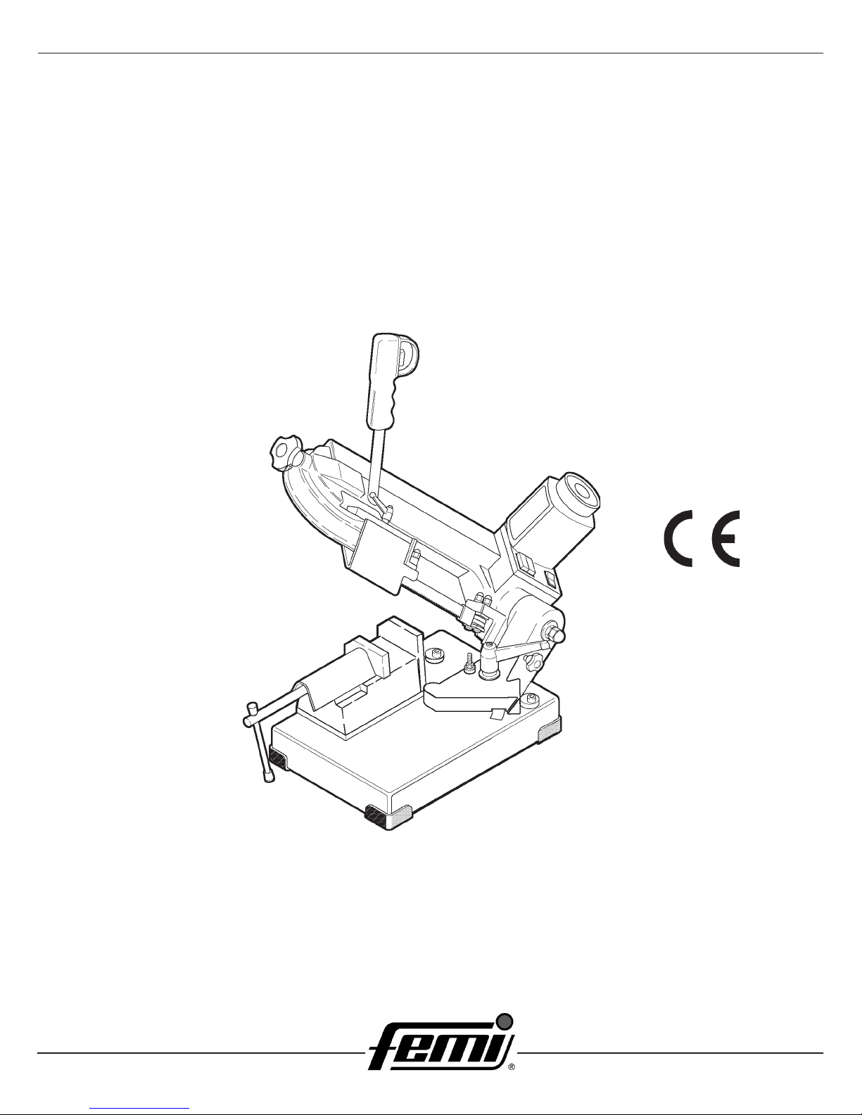
1.9 DESCRIZIONE DELLA MACCHINA (Fig. 1)
La segatrice a nastro e formata da due parti fondamentali:
il corpo macchina 5 completo di motore e di trasmissione
7, che e collegato solidalmente alla parte inferiore, formata
da base 13 e morsa 11, tramite il supporto girevole 9.
Qui di seguito, trovate un elenco delle parti principali, alle
quali corrisponde il numero che lo identifica nella figura.
Legenda Fig. 1
1. Impugnatura di comando
2. Volantino tensione lama
4. Guidalama scorrevole
5. Corpo macchina

3
IT
2.5 COLLEGAMENTO ELETTRICO
Controllate che limpianto rete sul quale inserite la macchina
sia collegato a terra come previsto dalle norme di sicurezza
vigenti, e che la presa di corrente sia in buono stato.
Si ricorda all utilizzatore che a monte dell impianto rete
deve essere presente una protezione magnetotermica atta
a salvaguardare tutti i conduttori dai corto circuiti e dai
sovraccarichi.
Tale protezione dovrà essere scelta in base alle
caratteristiche elettriche della macchina riportate sul motore.
Se dovesse verificarsi una mancanza di tensione
nellimpianto di rete, potete attendere che si
ristabilisca il collegamento senza che si creino
condizioni di pericolo: include infatti una funzione
di reset, che impedisce il riavviamento automatico
della macchina.
3 REGOLAZIONI (Fig. 4-5-6-7-8)
3.1 TENSIONE DELLA LAMA (Fig. 4)
Ruotate in senso orario il volantino B fino a fine corsa.
ATTENZIONE: Se la tensione è troppo elevata,
la lama tende ad uscire dalle guide; in questo
caso, allentate leggermente la tensione
ruotando di un giro il volantino B in senso
antiorario.
3.2 ARRESTO BARRA (Fig. 5)
Se dovete effettuare più tagli di pezzi tutti della stessa
lunghezza usate larresto barra in dotazione, evitando cosi
di rifare tutte le volte la stessa misura.
Avvitate lasta E nel foro della base e bloccatela con i dadi
F; allentate il volantino G e posizionate il fermo L alla
distanza necessaria dalla lama; ribloccate il volantino G.
3.3 ANGOLO DI TAGLIO (Fig. 6)
La segatrice consente di effettuare tagli con unangolazione
variabile fra 0 e 45 gradi; è sufficiente allentare la manopola
I e ruotare il supporto girevole J fino ai rispettivi fermi H e
K.
Per tutte le altre angolazioni intermedie, ruotate il supporto
girevole J fino a far coincidere lindice M posto su di esso
con la corrispondente posizione sulla targhetta.
Ribloccate quindi il supporto girevole.
3.4 VELOCITÀ DI TAGLIO (Fig. 7)
In base al tipo di materiale ed alla sua sezione (vedi TABELLA
DI TAGLIO) potete selezionare due diverse velocità di
taglio (60 oppure 80 m./min.) tramite il commutatore N.
6. Lama
7. Motore
8. Scatola comandi
9. Supporto girevole
10. Fermo barra
11. Morsa
12. Azionatore morsa
13. Base
PESO: ................................................................... 7 Kg.
DIMENSIONI: .... cm 85 x 36 x H65 nella configurazione
..................................................... di massimo ingombro.
DIMENSIONI IMBALLO: ..................... cm 72 x 34 x H52
2 INSTALLAZIONE
2.1 RIMOZIONE DELLIMBALLO
Rimuovete la scatola che protegge la macchina durante il
trasporto, avendo cura per quanto possibile di mantenere
limballo intatto, nel caso dobbiate spostare la segatrice
per lunghi tragitti oppure immagazzinarla per lunghi periodi.
2.2 MOVIMENTAZIONE (Fig. 2)
Dato il peso non eccessivo della macchina (Kg. 7), essa
potrà essere sollevata e movimentata da una sola persona,
impugnandola dal corpo macchina 5 opportunamente
bloccato (vedi punto 2.3).
2.3 TRAS ORTO (Fig. 2)
Per trasportare la macchina da un posto di lavoro ad un
altro, abbassate il corpo della segatrice fino a fine corsa ed
assicuratelo in tale posizione : è sufficiente inserire il perno
U nellapposito foro sul corpo e sollevare la macchina,
come mostra la Fig. 2.
Nel caso si renda necessario trasportare la macchina,
rimettetela nella scatola originale, facendo attenzione ad
inserirla nella giusta posizione rispetto alle frecce presenti
sullimballo.
Prestate molta attenzione agli ideogrammi stampati sulla
scatola che forniscono le indicazioni di pallettizzazione.
E buona norma fissare il carico con cinghie o corde di
sicurezza, per evitare spostamenti o cadute durante il
trasporto.
2.4 OSIZIONAMENTO/ OSTO DI LAVORO (Fig.
3)
Posizionate la macchina su un banco sufficientemente
piano, in modo che la macchina abbia la migliore stabilità
possibile. Per un eventuale fissaggio utilizzare gli appositi
fori previsti sulla base.
Per eseguire le lavorazioni tenendo conto dei criteri
ergonomici, laltezza ideale del banco deve essere quella
che vi consente di posizionare il piano della morsa tra i 90
ed i 95 centimetri da terra (vedi figura 3).
ATTENZIONE: Abbiate cura di posizionare la
macchina in una zona di lavoro adeguata sia
come condizioni ambiente che come
luminosità: ricordate sempre che le condizioni
generali dellambiente di lavoro sono
fondamentali nella prevenzione degli infortuni.

4
IT
ATTENZIONE: rima di iniziare ogni operazione
di taglio, accertatevi mediante un controllo a
vista che tutte le protezioni siano integre ed in
posizione adeguata.
Una volta eseguite tutte le procedure e le operazioni fin qui
descritte, potete iniziare le lavorazioni.
Per effettuare il taglio, disponetevi di fronte alla macchina,
ed impugnate con la mano destra limpugnatura.
ATTENZIONE: Tenete la mano sinistra sempre
lontana dalla zona di taglio e non cercate in
alcun modo di raggiungerla durante le
operazioni di taglio.
Premete con lindice della mano destra il pulsante di marcia
A (Fig. 4) ed abbassate gradualmente il corpo fino a mettere
a contatto dolcemente la lama con il pezzo da tagliare.
Iniziate ora ad applicare uno sforzo progressivo sul pezzo,
e completate il taglio.
ATTENZIONE: Fra un taglio ed un altro, nella
fase di posizionomento del pezzo, rilasciate
sempre il pulsante A, non cercate di bloccarlo
o di alterarne in alcun modo le caratteristiche
funzionali.
4.3 SOSTITUZIONE DELLA LAMA (Fig. 9)
CAUTELA: Quando effettuate questa operazione,
indossate sempre i guanti di protezione, al
fine di evitare contatti con i denti della lama.
- assicuratevi che linterruttore generale D sia sulla
posizione 0;
- allentate la maniglia Q e fate scorrere il guidalama
fino a fine corsa, seguendo il senso indicato dalla
freccia (Fig. 8);
- rimuovete il carter di protezione svitando le apposite
viti;
- allentate la tensione della lama ruotando in senso
antiorario il volantino B;
- con chiave mm. 0 allentate i dadi esagonali R dei due
guidalama esterni rispetto alla lama (Fig. 9);
- con la medesima chiave, ruotate leggermente in senso
antiorario la testa delle viti S degli stessi guidalama, in
modo da allontanarli dalla lama quel tanto che basta per
estrarla facilmente dalle guide;
- estraete la lama prima dalle guide e poi dalle pulegge
gommate;
- inserite la lama nuova prima tra le guide e poi sulle
pulegge gommate, con la dentatura orientata come in
figura 9;
- rimettete in tensione la lama, come descritto al punto
3. e riposizionate i guidalama esterni a leggero contatto
con la lama ruotando in senso orario la testa delle viti
S;
- ribloccate i due dadi esagonali R;
- rimontate il carter di protezione;
- riposizionate il guidalama scorrevole nella giusta
posizione per il taglio successivo.
3.5 GUIDALAMA SCORREVOLE (Fig. 8)
Il guidalama scorrevole con protezione integrata di cui e
dotata la vostra segatrice, vi consente di effettuare il
taglio mantenendo sempre guidata la parte di lama
necessaria, e di proteggere integralmente quella non
utilizzata nella lavorazione.
Allentate la maniglia Q e fate scorrere il guidalama in
modo da avvicinarlo o allontanarlo dal pezzo da tagliare,
come indicato in figura.
ATTENZIONE: Se questa regolazione non viene
effettuata, rimane scoperta una porzione di lama
non necessaria alla lavorazione, che puo
creare un rischio residuo di contatto con essa,
oltre a pregiudicare la qualità dei taglio.
3.6 CUSCINETTI GUIDALAMA (Fig. 9)
Per facilitare la sostituzione della lama e tenerla sempre
guidata al meglio, i guidalama esterni della segatrice sono
eccentrici e regolabili.
Essi devono sempre essere posizionati a leggero contatto
con la lama, in modo da ruotare al passaggio della stessa,
ma non completamente bloccati.
Per avvicinare o allontanare i guidalama eccentrici è
sufficiente ruotare leggermente con chiave mm. 0 la testa
delle viti S.
4 UTILIZZAZIONE
4.1 RODAGGIO DELLA LAMA
ATTENZIONE: Non effettuare una corretta
procedura di rodaggio significa compromettere
irrimediabilmente la precisione di taglio della
lama.
Per ottenere le migliori prestazioni, le lame bimetalliche che
corredano la vostra segatrice devono essere sottoposte
ad una breve procedura di rodaggio.
Occorre percio effettuare i primi due o tre tagli possibilmente
su un pezzo pieno D. 40 - 50 mm., esercitando sul pezzo
una pressione molto lieve, incrementandola man mano nei
tagli successivi.
Per rendervi conto di quale sia la pressione giusta nelle
normali condizioni di utilizzo definite da questo manuale
(vedi TABELLA DI TAGLIO), considerate ad esempio che il
primo taglio su un acciaio (es.C40) pieno D. 50 mm . deve
essere effettuato in circa 4 minuti; a rodaggio ultimato, lo
stesso pezzo puo essere tagliato tranquillamente in circa 2
minuti. Un rodaggio ben eseguito, comporta una migliore
qualità del taglio, sia come finitura che come precisione,
ed una maggiore durata della lama.
4.2 FUNZIONAMENTO (Fig. 7)
Premete il tasto verde dellinterruttore generale D, in
modo da abilitare la macchina al funzionamento.

5
IT
Per le esigenze particolari (vedi Tabella di taglio 4.6), ad
esempio per il taglio di grosse sezioni piene oppure di
profilati o angolari di piccolo spessore, sono disponibili
anche lame con dentatura 6, 4 oppure 8 denti per pollice.
MATERIALE: ........ M42 (acciaio per molle + acciaio HSS)
SVILUPPO : ...................................................... mm 330
ALTEZZA: .............................................................. mm 3
SPESSORE: ....................................................... mm 0,65
DENTATURA: ............................................. standard 8/ 2
............................................................... optional 6- 4- 8
6 ANUTENZIONE
6.1 INTERVENTI DI MANUTENZIONE ORDINARIA
Le normali operazioni di manutenzione ordinaria, effettuabili
anche da personale non specializzato, sono tutte descritte
nei paragrafi precedenti e nel presente.
. Prima di effettuare qualsiasi operazione di
manutenzione, disinserite la spina elettrica della
macchina dalla presa di corrente.
2. Durante le operazioni di manutenzione, indossate
sempre, per quanto possibile, i mezzi personali di
protezione (occhiali antinfortunistici e guanti di dimensioni
adatte).
3. Rimuovete i trucioli residui di lavorazione ogni qualvolta
si renda necessario, intervenendo nella zona di taglio e
sui guidalama.
E consigliato luso di un pennello o di un aspiratore.
ATTENZIONE: Non usate getti di aria compressa.
4. Se non utilizzate la segatrice per lungo tempo, ripulitela
e mettetela possibilimente in un luogo privo di umidità.
E buona norma, in questi casi, allentare la lama per
non mantenerla inutilmente in tensione.
6.2 ASSISTENZA
Nel caso sia necessario lintervento di personale qualificato
per operazioni di manutenzione straordinaria, oppure nel
caso di riparazioni sia in regime di garanzia che
successivamente, rivolgetevi sempre ad un Centro di
Assistenza autorizzato, oppure direttamente alla fabbrica,
se nella vostra regione non è presente il Centro di
Assistenza.
6.3 SMALTIMENTO MACCHINA, IMBALLAGGIO
Quando si rende necessario, alla fine
del normale ciclo di funzionamento,
rottamare la macchina, essa dovrà
essere conferita ad un Centro di
raccolta e smaltimento dei rifiuti
autorizzato al fine di rispettare le
Norme per ligiene e la salvaguardia
dellambiente.
Anche limballaggio va smaltito
secondo le normative vigenti, conferendolo a soggetti
autorizzati alla raccolta ed allo smaltimento o al recupero.
Rivolgetevi quindi al CONSORZIO DEGLI OLI USATI PIU
VICINO.
4.4 CA ACITÀ DI TAGLIO (Fig. 10)
La tabella di seguito riportata specifica le capacità di taglio
a 90 e 45 gradi ottenibili nelle normali condizioni di utilizzo
descritte in questo manuale, e senza interposizione di alcun
oggetto fra le ganasce della morsa.
0° = Ø 85 mm; 85 mm; 85x 05 mm
45° = Ø 70 mm; 60 mm; 60 x 70 mm
4.5 OSIZIONAMENTO CORRETTO DEL EZZO
IN MORSA (Fig. 11)
I pezzi da tagliare vanno inseriti direttamente fra le ganasce,
senza interposizione di altri oggetti.
Fig. 11
ATTENZIONE: Non tenete mai i pezzi da tagliare
in mano.
Quando il taglio riguarda i profilati, piatti o sagome
particolari, fare riferimento agli esempi di figura.
Se lo spessore del profilato dovesse essere molto sottile,
per evitare il suo schiacciamento tra le ganasce della
morsa, è meglio inserire allinterno del profilato stesso una
sagoma che ne copi il profilo.
4.6 TABELLA DI TAGLIO
5 ACCESSORI
5.1 SCELTA DELLA LAMA
La vostra segatrice è corredata di lama bimetallica
mm. 330x 3x0,65 con dentatura variabile 8/ 2 denti per
pollice, che copre gran parte dei tagli possibili con questa
macchina.
2002/96/EC

6
IT
Motore, cavo rete o spina difettosi.
Fusibili quadro elettrico bruciati.
Manca tensione nellimpianto di rete.
È intervenuto il termoprotettore
del motore.
Surriscaldamento del motore.
Sovraccarico del motore causato
da eccessiva pressione di taglio.
Guasto del motore.
La taratura dei fermi H e K (punto
3.3) non è esatta.
Pressione di taglio eccessiva (su
tubi e profilati).
Dentatura della lama non corretta
in relazione al pezzo da tagliare.
Velocità di taglio non corretta in
relazione al pezzo da tagliare.
Regolazione non corretta dei
guidalama eccentrici e scorrevole.
Errato posizionamento del pezzo in
morsa.
Scarsa tensione della lama.
La lama è consumata oppura non
ha dentatura adatta allo spessore
del pezzo che state tagliando.
Eccessiva pressione di taglio.
Regolazione non corretta dei
guidalama eccentrici.
Eccessivo consumo della
gommatura delle pulegge.
Slittamento della lama sulle pulegge,
causato da presenza di olio e grasso
per il taglio.
PROBLE A PROBABILE CAUSA RI EDIO SUGGERITO
Il motore non funziona.
Intervento
del termoprotettore.
Imprecisione
dellangolo di taglio a
90°-45°.
Imprecisione nello
squadro del taglio.
La finitura del taglio
risulta grezza o
ondulata.
La lama tende ad uscire
dalle guide.
Fate controllare la macchina da personale
specializzato; non tentate di riparare il motore da
soli.
Controllate lintegrità dei fusibili e sostituiteli se
necessario.
Controllate la presenza di tensione nellimpianto di
rete.
Attendete il normale ripristino del termoprotettore
(alcuni minuti) rilasciando il pulsante di marcia.
Controllate che le prese di aereazione del motore
siano libere da ostacoli.
Eseguite il taglio con la giusta pressione sul pezzo.
Fate controllare la macchina da personale
specializzato; non tentate di riparare il motore da
soli.
Effettuate la taratura allentando le viti di fissaggio e
riposizionando i fermi.
Diminuite la pressione di taglio.
Controllate i parametri di taglio (dentatura della lama,
velocità di taglio) nella tabella di taglio (punto 4.6).
Controllate la regolazione dei guidalama (punti 3.5 e
3.6).
Controllate il posizionamento ed il serraggio del pezzo
nella morsa (punto 4.5).
Controllate la tensione della lama (punto 3. )
Controllate i parametri di taglio (dentatura della lama,
velocità di taglio) nella tabella di taglio (punto 4.6).
Diminuite la pressione di taglio.
Controllate la regolazione dei guidalama eccentrici
(punto 3.6).
Fate controllare ed eventualmente sostituire le
pulegge da personale specializzato.
Non utilizzate assolutamente alcun lubrificante o
refrigerante per il taglio; fate controllare ed
eventualmente sostituire le pulegge da personale
specializzato.
7 GUIDA ALLA LOCALIZZAZIONE DEI GUASTI

7
EN
1 INTRODUCTION TO USE
Before starting work with your sawing machine, carefully
read this instructions manual so that you are familiar with
the machine and its uses and where it should not be used.
Keep this manual in a safe place.
It is an integral part of the machine and should be used for
reference in operating the machine correctly and in the
proper safety conditions.
Use the machine only and exclusively for the uses
specified below, as recommended in this manual. The
machine should not in any way be tampered with, or forced,
or used for unsuitable purposes.
1.1 SYMBOLS LACED IN CORRES ONDANCE
WITH USAGE OINTS
Never underestimate the warnings ATTENTION -
CAUTION given in this manual.
In order to draw the users attention and to preserve safety,
hazardous operation are preceded by symbols and notes
that point out the danger and explain how to behave to
avoid any risk.
These symbols and notes are divided in three categories,
identified by the following words:
ATTENTION: dangerous-behaviours that could
cause serious injuries.
CAUTION: behaviours that could cause slight
injuries or damages to things.
NOTE: the notes preceded by this symbols are
technical and are aimed at making operations easier.
INDEX
1 INTRODUCTION TO USE ...................................... 7
2 INSTALLATION ......................................................... 9
3 ADJUSTMENT .......................................................... 9
4 USE ........................................................................ 10
5 ACCESSORIES ...................................................... 11
6 MAINTENANCE ...................................................... 11
7 TROUBLESHOOTING ........................................... 12
1.2 SAFETY AND RULES
The machine was designed and built according to the
Community Directives in force: 98/37/CE - 2006/95/CE -
2004/108/CE.
The enclosed CE Declaration of conformity, togheter with
the CE mark on product, essentially comprise and are an
integral part of the machine: both guarantee product
conformity with the aforesaid safety Directives.
1.3 SAFETY LATES/LABELS
The safety plates/labels and indicators present on the
machine, the location of which is shown in the Figure 2,
are as follows:
- Wear noise protection devices.
- Wear safety masks or goggles.
- Do not insert the hands in this area with the
tool operating. Danger of dragging/cutting.
Matr. n. ...........
Fig. 12

8
EN
1.4 RECOMMENDED AND NOT
RECOMMENDED USAGE
This belt sawing machine was designed and constructed
according to the most advanced technologies and may be
used for all cutting requirements for metals commonly
used in industry and artisanship.
It can cut:
- COMMON STEELS (FE 37...)
- S ECIAL STEELS (C 40, 18NiCrMo5...)
- ALUMINIUM AND ITS ALLOYS
- BRASS
- BRONZE
- STEEL TUBING (FE 35, FE 52...)
- ROFILED SECTIONS IN SHEET METAL AND
ALUMINIUM
It is not suitable for cutting:
- WOOD AND SIMILAR MATERIALS
- BONE AND SIMILAR MATERIALS
ATTENTION: The band saw has been developed
and manufactured to cut in dry condition; the
use of any cooler by lubricating oil makes the
machine unusable.
Consult the relative sections for cutting capacities, the
speeds to use and the type of tools for use according to
the material to be cut and its section. (See list of contents).
1.5 STANDARD SAFETY ROCEDURS
- Do not use the machine in very damp places or in the
presence of inflammable liquids or gases.
- Do not use it in the open air when general weather and
environmental conditions are unfavourable (eg.
explosive atmospheres, during a storm or rain).
- Wear suitable clothes, without wide sleeves or articles
such as scarves, chains and bracelets which could
get caught in the moving parts.
- Always use personal protection devices: protective
goggles as recommended by safety standards, gloves
of the right size, headphones or earplugs, and hairnets
if necessary.
- Use the tools recommended in this manual if you want
to achieve the best performance from your sawing
machine.
- Any power cable extensions must be type approved
and comply with safety standards.
- Avoid using the machine if your psycho-physical
condition are precarious or upset.
1.6 SAFETY ROCEDURS FOR FURTHER RISK
- Always keep processing residues away from the cutting
area.
- Always use the clamp. The parts to be cut must always
be held firmly in the clamp.
- Always keep hands away from the working areas while
the machine is moving: before loading or unloading the
part, release the run button on the hand grip.
- Do not force the machine unnecessarily : excessive
cutting pressure could cause rapid wear to the blade
and negatively influence the performance of the
machine in terms of finishes and cutting precision.
1.7 INFORMATION REGARDING NOISE AND
VIBRATIONS
In normal conditions of use as described in this manual,
this belt sawing machine determines an equivalent level of
acoustic pressure:
Leq = 82 dB(A) when operating unloaded;
Leq = 84,3 dB(A) during processing (eg. cutting of a
steel tube D.80 mm thickness 5 mm), at cutting
speed of 80 m/min., with a weighted operating
cycle of minute.
The measurements are taken in accordance with
standards UNI7712, ISO3740, ISO 3746 and EEC 98/37.
The emission levels indicated are not necessarily safety
levels. Although there is a relationship between the
emissions and exposure levels, the values shown cannot
be used for establishing the need for further precautions.
There are other factors which influence the exposure levels
of operators, such as the features of the work place,
presence of other sources of noise, number of machines
running, etc.
The exposure levels may also vary between countries.
This information is necessary for the user for better
evaluation of the risks and hazards deriving from noise.
NOTE : ersonal hearing protection should be
used, such as headphones or earplugs.
1.8 INFORMATION ABOUT THE
ELECTROMAGNETIC COM ATIBILITY
The European regulations on safety and, in particular, the
EEC Directive 2004/108/CE contemplate that all the
equipment be equipped with shielding devices against radio
interferences both from and towards the outside.
This machine is equipped with filters both on the motor and
on the power supply through which the machine is safe and
in compliance with above regulations.
The frequency root mean RMS weighed for hand-arm
acceleration does not exceed 2.5m/s².
Tests were carried out according to 61000-6-1, EN 61000-
6-3, EN 55014-1, EN 55014-2 regulations.
1.9 DESCRI TION OF THE MACHINE (Fig.1)
The belt sawing machine consists of two basic parts: the
machine body 5 complete with motor and drive 7 which is
integrated into lower part, consisting of the clamp 11 and
the base 13, by means of the swivel support 9.
Here is a list of the main parts with the number indicating
it in the drawing.
Legend Fig. 1
1. Command grip
2. Blade tension handwheel
4. Sliding blade guide
5. Machine body
6. Blade
7. Motor
8. Control box
9. Bar stop
10. Clamp (vice)
11. Morsa
12. Clamp drive
13. Base

9
EN
WEIGHT: ............................................................... 7 Kg.
SIZE: .............................. cm 85 x 36 x H65 in maximum
.......................................................... overall dimensions.
PACKAGING SIZE: ............................. cm 72 x 34 x H52
2 INSTALLATION
2.1 REMOVING THE ACKING
Remove the wooden frame which protects the machine
during transit.
Try not to damage the frame as you may have to move
the machine long distances or store it for long periods.
2.2 HANDLING (Fig. 2)
As the machine is not heavy (Kg. 7), it can be lifted and
moved by a single person by gripping it from the machine
body 5, duly clamped (see pint 2.3).
2.3 TRANS ORT (Fig. 2)
It is necessary to low the saw body till the lower position
and fix it to the base : it is sufficient to insert the pin U in
the hole in the body, then lift the machine, gripping it as
showed in Fig. 2.
For transport the machine, it is better to place it in the box
it was when purchased.
Ensure it is placed in the correct position indicated by the
arrows on the packaging.
Pay careful attention to the ideogram printed on the box as
they provide all necessary information for palletization
and stacking of boxes.
Tying the load down with ropes or safety belts is
raccomended during transportation to prevent the load from
sliding or falling.
2.4 OSITION/WORK STATION (Fig. 3)
Place the machine on a sufficiently flat workbench so that
the machine has the better possible stability. Should you
wish to fix the machine in place, use the special holes
located on the base.
In respect of ergonomic criteria during cutting operations,
the workbench must be positioned at such a height that the
clamp level is between 90 and 95 cm from the ground (see
Fig. 3).
ATTENTION: Make sure that the machine is placed
in a working area with suitable environmental
conditions and lighting. The general conditions
of the working environment are of fundamental
importance for accident prevention.
2.5 ELECTRICAL CONNECTIONS
Check that the mains to which the machine is connected is
earthed in accordance with current safety regulations and
that the power point is in good condition.
Remember that there should be a magnetothermic
protective device fitted upstream of the mains to protect
all the conductors from short circuits and overloads.
The selection of this device should be in line with the
following electrical specifications of the machine stated on
the motor.
In case of power failure in mains, while you wait for
power to be restored there is no danger hazard may
arise: in fact, is also equipped with a reset function
which prevents the machine from restarting
automatically.
3 ADJUSTING (Fig. 4-5-6-7-8)
3.1 TENSION OF THE BLADE (Fig. 4)
Turn the handwheel B in a clockwise direction until it locks.
ATTENTION: If the tension is too high, the blade
tends to escape from the guide. In this case,
slacken the blade tension by turning of one/
two turns the handwheel B in a anti clockwise
direction.
3.2 BAR STO (Fig. 5)
Use the bar stop supplied if you have to do several cuts
on pieces of the same length.
In this way you do not have to repeat the same
measurement each time.
Screw rod E into the hole of the base and fasten it with nuts
F. Slacken the handwheel G and place the stop L at the
correct distance from the blade. Tighten handwheel G again.
3.3 CUTTING ANGLE (Fig. 6)
The band saw can cut at an angle varying from 0 to 45
degrees: it is sufficient to slacken the handle I and turn the
swiwel support J towards the respective limit stops H and
K.
For all intermediate angles, turn the swiwel support J until
the mark M on the support matches the corresponding
position on the plate.
Then lock the rotating support J again.
3.4 CUTTING S EED (Fig. 7)
Depending on the type of material and its section (see
CUTTING TABLE) you can choose two different cutting
speed 60 or 80 m/min. by means of the switch N.

10
EN
3.5 SLIDING BLADE GUIDE (Fig. 8)
The sliding blade guide with integrated protection fitted
on your sawing machine is used to perform the cut while
guiding the necessary part of the blade and fully protecting
the part not used in the cutting process.
Slacken the knobs Q and slide the blade guide so as to
move it closer to or further from the part to be cut, as
shown in the figure.
ATTENTION: If this adjustment is not done, the
part of the blade not used in the cutting process
will be exposed and this will create an extra
risk of contact, besides altering the quality of
the cut.
3.6 BEARINGS BLADE GUIDE (Fig. 9)
The blade-guide on the outside of the sawing machine are
eccentric and adjustable so as to simplify blade replacement
and to keep it guided as its best.
They must always touch the blade slightly, so that they
rotate when the blade passes, but must not be completly
locked.
In order to approach or remove the eccentric blade-guide,
gently turn the head of the screws S using a 0 mm.
wrenches key.
4 USE
4.1 RUNNING IN THE BLADE
ATTENTION: If the correct running in procedure
is not performed, the blades cutting precision
may be irreparably compromised.
To obtain the best performance, the bi-metal blades fitted
on your sawing machine must be run in for a short period.
For this reason the first two or three cuts should be done
where possible on a solid piece D.40-50 mm, using a very
slight pressure on the blade, and gradually increasing
pressure in subsequent cuts. To gauge the correct pressure
in normal operating conditions defined by this manual (see
cutting table), consider for example that the first cut on
solid steel (eg. C40) D.50 mm should be done in about 4
minutes.
After running-in, the same piece may easily be cut in
about 2 minutes. If the running-in process is done correctly,
the finish and precision of the cut will be of better quality
and the blade will last longer.
4.2 WORKING (Fig. 7)
Push the green button 1 of the main switch D to anable
machine operation.
ATTENTION: Before starting any cutting
operation, check that all the protections are
complete and in the correct position.
Once you have completed all the procedures and operations
described so far, you may start the working processes.
To perform the cut, move to the front of the machine and
grip the handgrip with your right hand.
ATTENTION: Keep your left hand away from the
cutting area and on no account try to reach it
when cutting is in process.
Using the index finger of your right hand, press the run
button A (Fig. 4) and gradually lower the machine body
until it comes lightly into contact with the part to be cut.
Now begin to apply gradual pressure on the part and
complete the cut.
ATTENTION: Always release button A between
one cutting operation and another, while you
are positioning the part. do not try to block it
or alter its functional characteristics in any
way.
4.3 RE LACING THE BLADE (Fig. 9)
CAUTION: When you perform this operation,
always wear protective gloves to avoid contact
with the teeth of the blade.
- check that the main switch D is at position 0;
- slacken the handle Q and slide the blade guide P as far
as it will go, following the direction on the arrow (Fig.
8);
- remove the protective casing unscrewing the four
screws;
- slacken the blade tension, turning the handwheel B in a
anti-clockwise direction;
- using a 0 mm. spanner, slacken the exagonal nuts R
on the two blade guides on the outside of the blade
(Fig. 9);
- with the same spanner gently turn the head of the
screws on the same blade-guide in a anti-clockwise
direction so as to move the bearings far enogh away
from the blade to enable you to extract it easily from
the guides;
- extract the blade first from the guides and then from
the rubber coated pulleys;
- insert the new blade first between the guides and then
onto the rubber coated pulleys, with the teeth facing as
showed in picture 9;
- put the blade under tension again as described in point
3. and reposition the two outer blade guides in slight
contact with the blade, turning the head of the screws
S in a clockwise direction;
- lock the two exagonal nuts R again;
- replace the protective casing, being careful to insert
the blade between the straps of the protection T;
- reposition the blade guides in the correct position for
the next cut.

11
EN
4.4 CUTTING CA ACITY (Fig. 10)
The table below specifies the cutting capacity at 90 and 45
degrees which may be obtained in normal conditions of use
described in this manual and without placing any other
object between the jaws of the clamp.
0° = Ø 85 mm; 85 mm; 85x 05 mm
45° = Ø 70 mm; 60 mm; 60 x 70 mm
4.5 CORRECT OSITIONING OF THE IECE IN
THE CLAM (Fig. 11)
The pieces to be cut should be fitted directly between the
jaws without adding other objects.
Fig. 11
ATTENTION: Never hold the pieces to be cut in
your hand.
When the pieces to be cut are profiled sections, flat pieces
or special shapes, refer to the examples shown in the
figures.
If the thickness of the profiled section is to be very thin,
an outline should be fitted which copies the profile inside
the profiled section itself to stop it being crushed between
the jaws.
4.6 CUTTING TABLE
For special requirements (see cutting table point 4.6), for
example, for cutting large solid sections or profiled sections
or corner pieces of small thickness, there are also blades
avail-able with 6, 4 or 8 teeth per inch.
MATERIAL: .......... M42 (acciaio per molle + acciaio HSS)
EXTENSION : .................................................... mm 330
HEIGHT: ................................................................ mm 3
THICKNESS: ..................................................... mm 0,65
TOOTHING: ............................................... standard 8/ 2
............................................................... optional 6- 4- 8
6 AINTENANCE
6.1 REGULAR MAINTENANCE
The operations of ordinary maintenance, which may also
be performed by non-specialist personnel, are all described
in the previous sections and here below.
. Before performing any maintenance operation,
disconnect the machine electric plug from the wall
outlet.
2. During maintenance operations, always wear personal
protection (safety goggles and gloves).
3. Remove the processing residues from the cutting area
and the blade guides whenever necessary.
You are advised to use a suction device or a brush.
ATTENTION: Do not use jets of compressed air.
4. If you do not intend to use the sawing machine for a
long time, clean it and put it in a dry place if possible.
In these cases it is advisable to slacken off the blade
so that it is not kept tight for no reason.
6.2 ASSISTENCE
Should it be necessary to call qualified personnel for
operations of extraordinary maintenance, or in the case of
repairs, under guarantee or at a later date, you should
always contact an authorized service centre or the factory
directly, if there is no service centre in your area.
6.3 DIS OSAL OF THE MACHINE, ACKING
At the end of the machine life, if the
machine must be scraped, contact
an authorised waste disposal centre
in order to comply with the Standards
for hygiene and environment
safeguard.
The packing must be disposed of
according to the ruling standards by
delivering it to authorised people for
the collection, disposal or reclaim.
Please contact the ASSOCIATION OF USED OILS near
to you.
5 ACCESSORIES
5.1 CHOISE OF BLADE
Your sawing machine is equipped with a bi-metal blade
measuring 330x 3x0.65 mm with variable toothing 8/ 2
teeth per inch, for use in the majority of cuts possible with
this machine.
2002/96/EC

12
EN
Defective motor, power cable or
plug.
Blown electric panel fuses.
No voltage in the mains system.
The overload cutout has tripped.
Motor overheating.
Motor overload caused by
excessive cutting pressure.
Motor breakdown.
The setting of the H and K retainers
(point 3.3) is inaccurate.
Excessive cutting pressure (on
pipes and section bars).
Incorrect blade toothing in relation
to the piece to cut.
Incorrect adjustment of the
eccentric and sliding blade-guides.
Incorrect cutting speed in relation
to the piece to cut.
The piece is wrongly positioned in
the vice.
Poor blade tension.
The blade is worn or its toothing is
not right for the thickness of the
piece being cut.
Excessive cutting pressure.
Excessive blade tension.
Incorrect eccentric blade-guide
adjustment.
Excessive wear of the pulley rubber
linings.
The blade slips on the pulleys,
caused by oil or grease required for
cutting operations.Check blade
tension (point 3. ).
The motor does not work.
Overload cutout tripped.
Inaccurate cutting angle at
90° - 45°.
Inaccurate cut squaring.
Cut finish is coarse or
corrugated.
The blade tends to
protrude from the guides.
Specialized personnel should check the machine; do
not attempt to repair the motor by yourself.
Check fuse integrity and replace, if necessary.
Check for voltage in the mains system.
Release the run button and wait a few minutes for the
overload cutout to reset.
Check that motor air intakes are clear.
Perform the cut on the piece at the correct pressure.
Specialized personnel should check the machine; do
not attempt to repair the machine by yourself.
Set the retainers by unloosening the fastening screws
and re-positioning them.
Decrease cutting pressure.
Check the cutting parameters (blade toothing, cutting
speed) in the cuts table (point 4.6).
Check blade-guide adjustment (points 3.5 and 3.6).
Check piece positioning and clamping in the vice
(point 4.5).
Check blade tension (point 3. ).
Check the cutting parameters (blade toothing, cutting
speed) in the cuts table (point 4.6).
Decrease cutting pressure.
Check eccentric blade-guide adjustment (point 3.6).
Specialized personnel should check the pulleys and
replace them if necessary.
Never use any type of lubricant or coolant for the
cutting operations; specialized personnel should check
and, if necessary, replace the pulleys.
PROBLE S PROBLE S CAUSES SOLUTIONS SUGGESTED
7 TROUBLESHOOTING

13
DE
1 EINFÜHRUNG
Lesen Sie die Gebrauchsanweisung aufmerksam durch,
bevor Sie mit Ihrer Bandsäge zu arbeiten beginnen und
lernen Sie die Maschine, ihren Einsatz und Grenzen genau
zu kennen.
Bewahren Sie dieses Heft sorgfältig auf: es gehört zur
Maschine.
Befolgen Sie für alle Arbeiten an der Maschine die
beschriebenen Anweisungen und Sicherheitsmassnahmen.
Setzen Sie die Maschine nur für die folgend beschriebenen
und empfohlenen Arbeiten ein ohne sie zu forcieren,
abzuändern oder sie zweckfremd zu gebrauchen.
1.1 SYMBOLE UND KENNZEICHEN
Bitte die Anweisungen ACHTUNG - VORSICHT - MERKE
im Handbuch nicht unterschätzen.
Um die Aufmerksamkeit zu wecken und um Sicherheits-
signale zu geben, erscheinen bei gefährlichen Arbeiten
Symbole und Anmerkung, die das Risiko bei der Arbeit
hervorheben und zugleich erklären, wie man sich zu verhalten
hat, um Gefahren zu vermeiden.
Es handelt sich um drei Symbole, die durch folgende
Worte gekennzeichnet sind:
ACHTUNG: gefährliches Verhalten, das zu
schweren Verletztungen führen kann.
VORSICHT: Verhalten, das zu Verletzungen oder
Schäden an Gegenständen führen.
MERKE : Anmerkungen, die dieses Symbol haben,
betreffen technische Hilfen, die Arbeiten erleichtern
können.
INHALT
1 EINFÜHRUNG ................................................... 13
2 INSTALLIEREN .................................................. 15
3 EINSTELLUNGEN ............................................. 15
4 GEBRAUCH ....................................................... 16
5 MASCHINENTEILE ............................................ 17
6 WARTUNG ......................................................... 17
7 STÖRUNGSSUCHE UND - BEHEBUNG ......... 18
1.2 SICHERHEIT UND NORMEN
Die Maschine wurde so konzipiert und gebaut, daß sie den
Anforderungen der gültigen EG Richtlinien entspricht: 98/
37/EWG - 2006/95/EWG - 2004/108/EWG.
Die beiliegende EG Konformitätserklärung ist, zusammen
mit dem auf dem Produkt angebrachten CE Kennzeichen,
ein grundlegendes Element und ein wesentlicher Teil der
Maschine: sie ist eine Garantie, daß das Produkt den o. g.
Sicherheitsrichtlinien entspricht.
1.3 SICHERHEITSSCHILDER/-AUFKLEBER
An der Maschine sind folgende Sicherheits- und
Hinweisschilder/-Aufkleber in der Postion gemäß Abbildung
2 angebracht:
- Gehörschutz benutzen
- Gesichts- oder Augenschutz benutzen.
- Einführen der Hände in diesen Bereich
verboten, Werkzeuge sind in Betrieb.
Einzugs-/Schnitt.
Matr. n. ...........
Abb. 12

14
DE
1.4 EINSATZGEBIET UND UNGEEIGNETER
EINSATZ
Die Bandsägemaschine wurde unter Einsatz neuester
Technologie entwickelt und realisiert.
Sie befriedigt alle Anforderungen des typischen
Metallsägens der Industrie und des Handwerks.
Geeignet zum Sägen von:
- NORMALSTAHL (FE 37...)
- S EZIALSTAHL (C 40, 18NiCrMo5...)
- ALUMINIUM UND ALU-LEGIERUNGEN
- MESSING
- BRONZE
- STAHLROHRE (FE 35, FE 52...)
- BLECH- UND ALUMINIUM ROFILE
Nicht geeignet zum Sägen von:
- HOLZ UND ÄHNLICHE MATERIALEN
- KNOCHEN UND ÄHNLICHE MATERIALEN
ACHTUNG: Die Bandsägemaschine wurde zum
Trockenschneiden konzipiert und gebaut.
Durch die Verwendung eines Schmier-/
Kühlmittels wird die Maschine untauglich.
Bitte konsultieren Sie die einzelnen im Inhaltsverzeichnis
gelisteten Kapitel um mehr zu erfahren über
Schnittkapazität, Schnittgeschwindigkeit und zu
gebrauchendes, geeignetes Werkzeug.
1.5 ALLGEMEINE SICHERVORSCHRIFTEN
- Gebrauchen Sie die Maschine nicht in feuchten Räumen,
in Nähe von explosiven Substanzen oder Gas.
- Arbeiten Sie nicht im Freien wenn die Wetterbedingungen
es nicht zulassen (Niederschlag, Gewitter) oder wenn
explosive Substanzen in der Nähe oder in der
Atmosphäre sind.
- Achten Sie auf geeignete Arbeitskleidung : vermeiden
Sie weite Ärmel sowie Hlstucke die sich verfangen
könnten in den beweglichen Maschinenteilen.
- Verwenden Sie stets persönliche Sicherheitshilfmittel:
normentsprechende Sicherheitsbrillen, Handschuhe die
der Handgrösse entsprechen, Ohrschutz und Haarnetze
bei Bedarf.
- Um immer das beste Resultat mit Ihrer Säge zu
erreichen sollten Sie die empfohlenen Werkzeuge
gebrauchen.
- Eventuelle Verlängerungen für das Stromkabel müssen
eine Zulassung haben und den einschlägigen
Sicherheitsbestimmungen entsprechen.
- Vermeiden .
1.6 SICHERVORSCHRIFTEN FÜR WEITERE
RISIKEN
- Halten Sie die Arbeitszone im Schnittbereich stets sauber
von Schnitt- resten.
- Gebrauchen Sie immer den Schraubstock: die
Werkstücke müssen immer fest im Schraubstock
eingespannt sein.
- Halten Sie die Hände fern der Arbeitszone während die
Maschine in Bewegung ist. Bevor Sie Laden und
Entladen müssen Sie immer darauf achten, dass Sie
den Schalter im Handgriff nicht drücken.
- Forcieren Sie die Maschine nicht unnötig: ein zu starker
Druck auf die Klinge verringert deren Lebensdauer und
bedingt eine Verschlechterung der allgemeinen
Leistungen der Maschine sowie eine Verringerung der
Schnittpräzision.
1.7 INFORMATIONEN ZU SCHALLEMISSIONEN
UND VIBRATIONEN
Die Bandsägemaschine erzeugt bei normalem Gebrauch,
beschrieben in diesem Heft, die folgende
Geräuschentwicklung:
Leq = 82 db (A) bei Leerlauf;
Leq = 84,3 dB (A) während Arbeitszyklus von rund Minute
beim Schneiden von beispielsweise: Stahlrohr mit
Durchmesser 80 mm und 5 mm Stärke.
Der gewichtete quadratische Mittelwert der Beschleunigung
Hand-Arm in Frequenz übersteigt 2.5m/s² nicht.
Die Messungen wurden nach UNI7712, ISO3740, ISO
3746 und EWG 98/37 durchgeführt.
Die angegebenen Emissionspegel sind nicht unbedingt als
Sicherheitspegel zu betrachten. Trotz des Zusammenhangs
zwischen Emissions- und Expositionspegel dürfen die
angeführten Werte nicht zur Festlegung weiterer
Vorsichtsmaßnahmen herangezogen werden. Die
Expositionspegel der Bedienpersonen werden durch andere
Größen beeinflusst, u.z. die Eigenschaften des
Arbeitsumfelds, das Vorliegen sonstiger Schallquellen, die
Anzahl der laufenden Maschinen usw. Die Expositionspegel
sind außerdem von länderspezifischen Vorgaben abhängig.
Anhand dieser Information kann der Anwender Risiken und
Gefährdungen durch Schallemissionen bestmöglich
auswerten. Bei besonderen Bedürfnissen (siehe
Schnitttabelle 4.6), z.B. das Schneiden großen Vollmaterials
oder dünner Profile, sind ebenfalls Sägebänder mit
verschiedener Zähnezahl erhältlich.
MERKE: Wir empfehlen den Gebrauch von
persönlichem internen oder externen
Gehörschutz.
1.8 INFORMATIONEN ÜBER DIE
ELEKTROMAGNETISCHE VERTRÄGLICHKEIT
Die neuesten Europäischen Sicherheitsbestimmungen und
insbesondere die Richtlinie 2004/108/EWG schreiben vor,
daß alle Apparate mit Schutzeinrichtungen gegen
Funkstörungen von und in die Außenumgebung ausgestattet
sein müssen. Diese Maschine besitzt sowohl am Motor als
auch auf der Zuführung Störfilter, wodurch ein sicherer und
vorschriftsgemäßer Betrieb gewährleistet ist.
Die rüfungen wurden gemäß den Normen EN 61000-
6-1, EN 61000-6-3, EN 55014-1, EN 55014-2 durchgeführt.
1.9 BESCHREIBUNG DER MASCHINE (Abb.1)
Die Bandsägemaschine besteht aus zwei wichtigen Teilen:
der Maschinenkörper 5, komplett mit Antriebsmotor 7 und
der untere Teil bestehend aus Sockels 13 und Schraubstock
11. Die Teile sind solid verbunden durch die Drehhalterung
9. Folgend finden Sie eine Liste der wichtigsten Teile. Die
Nummern entsprechen den Nummern auf der Abbildung.
Legende Abb. 1
1. Handgriff mit Schalter
2. Sägeblattspannungs-Griff

15
DE
4. Verstellbare Sägeblattführung
5. Maschinenkörper
6. Sägeblatt
7. Motor
8. Schalterblock
9. Drehhalterung
10. Anschlag
11. Schraubstock
12. Schraubstock-Griff
13. Sockel
GEWICHT: ............................................................ 7 Kg.
PLATZBEDARF: ........................ cm 85 x 36 x H65 in der
............................... Konfiguration maximaler Platzbedarf
VERPACKUNG-AUSSENMASS: ......... cm 72 x 34 x H52
2 INSTALLIEREN
2.1 ENTFERNEN DER VER ACKUNG
Die Maschine aus der Verpackung herausnehmen. Bitte
die Schalchtel sorfalting aufbewahren, solten Sie die
Maschine transportieren oder langere Zeit lagern wollen.
2.2 STANDORTVERÄNDERUNG (Abb.2)
Da die Maschine nicht schwer ist ( 7 Kg.), kann sie von
einer einzige Person angehoben und gehandabbt werden.
Heben Sie die Maschine am Maschinenkorper 5 an, der in
geeigneter weise befestigt sein muss.
2.3 TRANS ORT (Abb. 2)
Um die Maschine dann zu transportieren wird erst der
Sägebügel bis zum Anschlag niedergedrückt und dort
befestigt : dazu genügt es, den Zapfen U in die dafür
vorgesehene Öffnung am Maschinenkörper zu stecken
und die Maschine anzuheben; diese dabei wie auf Abb.2
dargestellt halten. Falls die Maschine transportiert werden
muss, stellen Sie in ihre Originalverpackung, in der sie
geliefert wurde, und passen dabei auf, dass sie in der
richtigen Position eingeführt wird (siehe Pfeile auf der
Schachtel). Beachten Sie bitte die Symbole auf der
Verpackung genau, denn sie zeigen, wieviele Schachtel
auf Pallets gepackt oder übereinander gestapelt werden
können. Wenn möglich, soll die Ladung mit Seilen oder
Sicherheitsriemen fixiert werden, damit es während des
Transport nicht zu Verschiebungen kommt oder Teile der
Ladung sogar herausfallen.
2.4 OSITIONIERUNG/ARBEITS LATZ (Abb. 3)
Stellen Sie die Maschine auf einen ebenen Werkbank um
die grösstmögliche Stabilität zu erhalten.
Zum Befestigen die hierfür vorgesehenen Löcher im Sockel
verwenden. Wenn beim Arbeiten auf die ergonomischen
Kriterien Rücksicht genommen wird, soll die Höhe der
Schraubstockfläche zwischen 90 - 95 cm ab Boden sein
(Abb. 3).
ACHTUNG: Achten Sie darauf dass die Maschine
in einer geeigneten Arbeitszone posizioniert
wird, welche den Anforderungen bezüglich der
allgemeinen räumlichen Bedingungen und
Lichtvor- kommen entspricht. Beachten Sie
dass die räumlichen Bedingungen die Basis
aller unfallverhütenden Massnahmen sind.
2.5 ELEKTRISCHER ANSCHLUSS
Kontrollieren Sie ob Ihr Anschluss über eine Erdung verfügt
entsprechend den geltenden Sicherheitsnormen und ob sich
Ihre Steckdose in einwandfreiem Zustand befindet.
Wir erinnern den Gebraucher dass das Netz über eine
magnetthermische Sicherung verfügen muss, welche in
der Lage sein muss die Anlage vor Kurzschluss und
Überlastung zu schützen.
Diese Schutzvorrichtung kann auch aufgrund der
nachfolgend aufgelisteten elektrischen Eigenschaften der
Maschine am motor angegeben.
Bei einem Stromausfall im Stromnetz können Sie auf
die Rückkehr warten, ohne daß sich dadurch eine
Gefahrensituation ergibt.
Enthält eine Resetfunktion, der den automatischen
Neustart der Maschine in diesen Fällen verhindert.
3 EINSTELLUNG (Abb. 4-5-6-7-8)
3.1 SÄGEBLATTES REGULIERT (Abb.4)
Drehen Sie das Handrad B im Uhrzeigersinn bis er einrastet.
Bei zu hoher Spannung neigt das Sägeblatt dazu, aus den
Führungen zu rutschen.
In diesem Fall, lockern Sie leicht die Spannung indem Sie
das Handrad B einmal gegen den Uhrzeigersinn drehem.
3.2 ANSCHLAG (Abb. 5)
Wenn Sie mehrere Schnitte gleichlanger Werkstücke
erzielen möchten gebrauchen Sie den mitgelieferten
Anschlag. Sie vermeiden so jedesmal erneut die Längen
messen zu müssen.
Schrauben Sie den Schaft E in das Loch im Schraubstock
und ziehen Sie nun die Mutter F fest; lockern Sie das Rad
G und positionieren Sie den Anschlag L in der gewünschten
Distanz zur Klinge; befestigen Sie nun das Rad G.
3.3 SCHNITTWINKLEL (Abb.6)
Die Sägemaschine ermöglicht, Schnitte mit einer von 0°
bis 45° verstellbaren Gehrung durchzuführen : es braucht
nur der Griff I, und die Drehauflage J bis zu den
entsprechend Endlanschlägen H und K gedreht zu werden.
Für alle anderen, dazwischenliegenden Werte dreht man
die Drehauflage, bis die darauf befindliche Anzeige M mit
der entsprechenden Stelle am Schild übereinstimmt.
Dann die Drehauflage wieder blockieren.
3.4 SCHNITTWINDIGKEIT (Abb.7)
Je nach Materialart und stärke (Siehe Schnitt-Tabelle) hat
man die Wahl zwischen zwei verschiedenen
Schnittwindigkeiten (60 oder 80 m/ Min.) die mitt dem
umschalter N eingestellt werden.

16
DE
3.5 SÄGEBLATTFÜHRUNG (Abb. 8)
Die verstellbaren Bandführungen P über welche Ihre Säge
verfügt sind voll geschützt, führen den Teil der Klinge der
trennt und schützen den nicht gebrauchten Teil der Klinge
vor Überbeanspruchung.
Lösen Sie den Griff Q und nähern Sie die Führung P an das
Werkstück oder umgekehrt falls Sie die Spannweite erhöhen
wollen.
ACHTUNG: Wenn Sie die Bandführung nicht
einstellen, bleibt ein Teil der Klinge unbenutzt
und ungeschützt. Das bedeutet Gefahr eines
Kontakts und kann ausserdem die
Schnittqualität beeinträchtigen.
3.6 LAGER DER SÄGEBLATTFÜHRUNG (Abb. 9)
Damit sich das Sägeblatt leichter auswechseln lässt und
immer optimal geführt wird, sind die äusseren
Sägeblattführungen exzentrish und verstellbar.
Sie müssen immer so positioniert sein, dass sie das
Sägeblatt leicht berühren und sich bei dessen Durchgang
drehen; sie dürfen nicht vollständig blockiert sein.
Zum Annähern und Entfernen der exzentrischen
Sägeblattführungen genügt es, mit einem 0 mm. Schlüssel
den Kopf der Schrauben S leicht zu drehen.
4 GEBRAUCH
4.1 EINLAUFEN DES SÄGEBLATTES
ACHTUNG: Eine Missachtung der korrekten
Einlaufprozedur beeinträchtigt definitiv die
Schnittpräzision des Messers.
Um die besten Schnittresultate zu erzielen müssen die
mitgelieferten Bimetallklingen einer kurzen Einlaufzeit
unterzogen werden. Die ersten drei Schnitte sollten auf
einem vollen Rundstück mit Durchmesser 40-50mm
ausgeführt werden. Der Druck auf das Werkstück soll
während diesen Schnitten nur leicht sein und wird von
Schnitt zu Schnitt etwas erhöht.
Um Ihnen ein Beispiel über den richtigen Druck während
der Einlaufzeit zu geben, bei normalen Arbeitsbedingungen
definiert in diesem Heft (siehe Schnitt-Tabelle), betrachten
wir den ersten Schnitt auf Voll Stahl (C40), mit Durchmesser
50mm. Während die Schnittzeit beim Einlaufen rund 4
Minuten beträgt kann dasselbe Material nachher in rund 2
Minuten geschnitten werden.
Ein korrekt ausgeführtes Einlaufen bewirkt eine höhere
Qualität des Schnittes und dessen Präzision sowohl eine
verlängerte Lebensdauer der Klinge.
4.2 BETRIEB (Abb. 7)
Auf den grüne Drukknopf des Haupschalter D drücken,
damit die maschine betriebfähig wird.
ACHTUNG: Bevor Sie mit der Arbeit beginnen,
sollten Sie jedesmal alle Schutzvorrichtungen
kontrollieren auf korrekte Stellung und
Unversehrtheit.
Nachdem Sie alle bisher beschriebenen Anleitungen befolgt
haben können Sie nun mit dem eigentlichen Arbeiten
beginnen.
Bringen Sie sich vor der Maschine in Stellung und halten
Sie den Handgriff am Sägearm mit der rechten Hand.
ACHTUNG: Halten Sie Ihre linke Hand immer
ausserhalb der Schnittzone und versuchen Sie
nicht diese zu erreichen während des
Schneidens.
Drücken Sie den Schalter A (Abb.4) im Handgriff und nähern
Sie den Sägearm langsam dem zu schneidenden Werkstück
bis zum Kontakt.
Erst jetzt üben Sie mehr Druck auf den Sägearm aus bis
zum Abschliessen des Schnittes.
ACHTUNG: Zwischen zwei
aufeinanderfolgenden Schnitten darf der
Schalter A nie gedrückt werden. blockieren oder
manipulieren Sie diesen oder andere
Funktionen nie.
4.3 WECHSEL DES SÄGEBLATTES (Abb. 9)
VORSICHT: Tragen Sie während des
Klingenwechsels immer Handschuhe um einen
Kontakt mit den Klingenzähnen zu vermeiden.
- versichern Sie sich dass sich der Hauptschalter D auf
0 Position befindet;
- Den Griff Q lockern und die Sägeblattführung in Pfeil
Richtung bis zum Endanschlag zuruck schieben;
- das Schutzgehäuse durch Lösen der vier Schrauben
entfernen;
- die Spannung des Sägeblattes lockern das Handrad B
gegen den Uhrzeigersinn drehen;
- mit einem 0 mm. Schlüssel die Seckscantmuttern R
der beiden aüsseren Sägeblattführungen lockern;
- mit demselben Schlüssel den Schraubkpf S derselben
Sägeblattführungen leicht gegen den Uhrzeigersinn
drehen, um die Lager gerade so weit vom Sägeblatt zu
entfernen, dass diesen leicht aus der Führungen
genommen werden kann;
- das Sägeblatt zuerst aus den Führungen und dann von
den Gummischeiben nehmen;
- das neue Sägeblatt in die Führungen und dann auf die
Gummischeiben einsetzen; die Zanhung muss dabei
wie auf Abb.9 dargestellt ausgerichtet sein;
- das Sägeblatt wieder, wie unter punkt 3. beschrieben
spannen und die beiden äusseren Sägeblattführungen
so positionieren, dass sie das Sägeblatt kaum berühren,
dazu den Schraubenkopf S im Uhrzeigersinn drehen;
die beiden Seckscantmuttern R wieder anziehen;
die Sägeblattführungen in die richtige Stellung für die
darauffolgende Schneidearbeit bringen.
Other manuals for 780P
1
Table of contents
Languages:
Other Femi Saw manuals

Femi
Femi TR 1030DB User manual

Femi
Femi 732 User manual

Femi
Femi 787XL Specification sheet

Femi
Femi 280 Specification sheet

Femi
Femi JOB LINE TR 1030 DB Service manual

Femi
Femi 782 Specification sheet

Femi
Femi 2200 Specification sheet

Femi
Femi N266DA XL User manual

Femi
Femi 1050 3D Specification sheet

Femi
Femi 999 Specification sheet