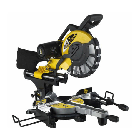
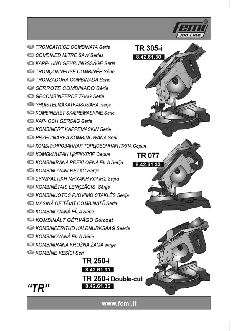
Femi XXX Specification sheet

ISTRUZIONI PER LUSO E MANUTENZIONE
INSTRUCTIONS FOR USE AND MAINTENANCE
GEBRAUCHSANLEITUNGEN UND WARTUNG
MODE DEMPLOI ET ENTRETIEN
INSTRUCCIONES PARA EL USO Y MANUTENCION
INSTRUÇÕES DE UTILIZAÇÃO
CERTIFICATA
CERTIFIED
GEPRÜFT
CERTIFIE
CERTIFICADA
CERTIFICADA
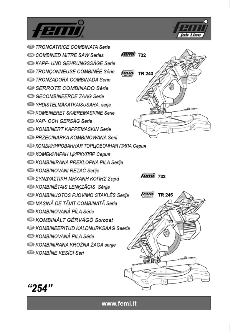
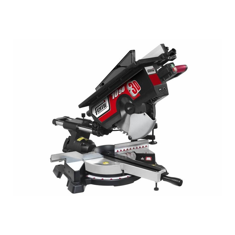
TRONCATRICE CIRCOLARE
MITRE-SAW
KREISSÄGE
SCIE A ONGLET
TRONZADORA
SERRA CIRCULAR
www.femi.it
art. XXX
art. XXX-ALU

DICHIARAZIONE DI CONFORMITÁ CE
DEL COSTRUTTORE FEMI S.p.A.
Via del Lavoro, 4 - 40023 Castel Guelfo (BO) - ITALIA
Tel. 39-0542-670160 - Fax 39-0542-670185 - http://www.femi.it
Dichiara sotto la nostra esclusiva responsabilità che questa
macchina è conforme alle disposizioni della Direttiva Macchine 98/
37/CE ed è identico, in quanto incluso nell allegato IV della direttiva,
al macchinario oggetto della certificazione CE di tipo (vedi etichetta
riportata) rilasciata da ICE Istituto Certificazione Europea SpA,
organismo notificato n. 0303. E inoltre conforme alle disposizioni
delle seguenti altre direttive: 2006/95/CE, 2004/ 08/CE.
ITALIANO (IT) ................................................................................................................. 5 ÷ 10
ENGLISH (EN) .............................................................................................................. 11 ÷ 18
DEUTSCH (DE) ............................................................................................................ 19 ÷ 25
FRANCAIS (FR) ........................................................................................................... 26 ÷ 32
ESPANOL (ES) ............................................................................................................. 33 ÷ 39
PORTUGUÊS (PT) ....................................................................................................... 40 ÷ 46
COMPLIANCE DECLARATION CE
OF THE BUILDER FEMI S.p.A.
Via del Lavoro, 4 - 40023 Castel Guelfo (BO) - ITALIA
Tel. 39-0542-670160 - Fax 39-0542-670185 - http://www.femi.it
Declare under our sole responsibility that the machine,to which this
declaration relates, is in conformity with the regulations indicated in
Machinery Directive 98/37/CE and is identical, in that it is included
in appendix IV of the directive, to the machinery concerning CE
certification type (see relative label) issued by the ICE (Istituto
Certificazione Europea SpA), Notified Body no. 0303. Furthermore
it is also in conformity with the following standards: 2006/95/CE,
2004/ 08/CE.
CE KONFORMITATS ERKLARUNG
DES HERSTELLER FEMI S.p.A.
Via del Lavoro, 4 - 40023 Castel Guelfo (BO) - ITALIA
Tel. 39-0542-670160 - Fax 39-0542-670185 - http://www.femi.it
Erklärt unter seiner alleinigen Verantwortung, dass diese Maschine
den Bestimmungen der Maschinenrichtlinie 98/37/EWG entspricht,
und, insofern eingeschlossen in Anhang IV der Richtlinie, identisch
mit der maschinellen Ausrüstung ist, die Gegenstand der EG-
Baumusterbescheinigung ist (siehe das abgebildete Etikett), die
vom ICE (Istituto Certificazione Europea SpA, anerkannte Prüfstelle
Nr. 0303) erlassen wurde. Sie entspricht ferner den Bestimmungen
der folgenden weiteren Richtlinien: 2006/95/EWG, 2004/ 08/WG.
DECLARATION DE CONFORMITE CE DU CONSTRUCTEUR
FEMI S.p.A.
Via del Lavoro, 4 - 40023 Castel Guelfo (BO) - ITALIA
Tel. 39-0542-670160 - Fax 39-0542-670185 - http://www.femi.it
Déclare, sous sa propre responsabilité, que cette machine est
conforme aux dispositions de la Directive Machines 98/37/CE et
est identique, car incluse dans lannexe IV de la directive, à la
machine objet de la certification CE de type (voir étiquette rapportée)
remise par ICE Istituto Certificazione Europea SpA, organisme
notifié n° 0303. En outre, elle est conforme aux dispositions des
autres directives suivantes: 2006/95/CE, 2004/ 08/CE.
DECLARATION DE CONFORMIDAD CE
DEL CONSTRUCTOR FEMI S.p.A.
Via del Lavoro, 4 - 40023 Castel Guelfo (BO) - ITALIA
Tel. 39-0542-670160 - Fax 39-0542-670185 - http://www.femi.it
Declara bajo su exclusiva responsabilidad que esta máquina cumple
con lo dispuesto por la Directiva Máquinas 98/37/CE y es idéntica,
en cuanto máquina que figura en el anexo IV de la directiva, a la
máquina objeto de la certificación CE de tipo (véase etiqueta
ilustrada) otorgada por ICE Instituto de Certificación Europea SpA,
organismo notificado nº 0303.
Asimismo, cumple también con lo dispuesto por las siguientes
directivas: 2006/95/CE y 2004/ 08/CE.
DECLARAÇÃO DE CONFORMIDADE CE DO CONSTRUTTORE
FEMI S.p.A.
Via del Lavoro, 4 - 40023 Castel Guelfo (BO) - ITALIA
Tel. 39-0542-670160 - Fax 39-0542-670185 - http://www.femi.it
Declaramos sob a nossa exclusiva responsabilidade que esta
máquina está em conformidade com as disposições da Directiva
Máquinas 98/37/CE e que é idêntica, porque contemplada no anexo
IV da directiva, ao maquinário objecto da certificação CE de tipo
(ver a etiqueta indicada) emitida por ICE Istituto Certificazione
Europea SpA, organismo notificado nº 0303. Está também em
conformidade com as disposições das seguintes directivas: 2006/
95/CE, 2004/ 08/CE.
INGOMBRO PER ETICHETTA


SCHEMA ELETTRICO / WIRING DIAGRAM / ELEKTRISCHER SCHALTPLAN - /
SCHEME ELECTRIQUE / ESQUEMA ELECTRICO / ESQUEMA ELÉCTRICO
F
Moteur
Condensateur
Bouton marche
Connecteurs Faston
Carte electronique
Bleu
Marron
Jaune
Noir
Blanc
Rouge
D
Motor
Kondensator
Handschalter
Faston E-Verbindung
E-Karte
Blau
Braun
Gelb
Schwarz
Weiss
Rot
E
Motor
Condensador
Pulsador de marica
Conexiònes Faston
Ficha electrònica
Azul
Marron
Amarillo
Negro
Blanco
Rojo
P
Motor
Condensador
Botão de arranque
LigacaoFaston
Placa electronica
Azul
Castanho
Amarelo
Preto
Branco
Vermelho
GB
Motor
Condensator
Start switch
Faston conne
Electronic card
Blue
Brown
Yellow
Black
White
Red
I
Motore
Condensatore
Pulsante di marcia
Connettori Faston
Scheda elettronica
Blu
Marrone
Giallo
Nero
Bianco
Rosso
M
C
PM
F..
E
1
2
3
4
5
6

5
IT
1 INTRODUZIONE ALL’USO .................................... 5
2 INSTALLAZIONE ...................................................... 7
3 REGOLAZIONI ........................................................ 8
4 UTILIZZAZIONE ...................................................... 8
5 ACCESSORI .......................................................... 10
6 MANUTENZIONE ................................................... 10
7 GUIDA ALLA LOCALIZZAZIONE DEI GUASTI ..... 11
INDICE
1 INTRODUZIONE ALL’USO
Prima di iniziare le lavorazioni con la Vostra troncatrice,
leggete attentamente questo manuale di istruzioni, allo scopo
di conoscere la macchina ed i suoi impieghi, e le eventuali
controindicazioni.
Conservate con cura questo manuale: esso fa parte
integrante della macchina, e ad esso dovrete sempre riferirvi
per eseguire al meglio e nelle massime condizioni di sicurezza
le operazioni che in esso sono descritte.
Il manuale và tenuto sempre insieme alla macchina, a
portata di mano per potere essere consultato ogni volta si
renda necessario.
Utilizzate la macchina solo ed esclusivamente per gli
impieghi di seguito specificati, usandola come
raccomandato in questo manuale, e non cercando in alcun
modo di manometterla o forzarla, o di usarla per scopi non
adatti.
1.1 COLLOCAZIONE IN CORRISPONDENZA DEI
PUNTI D’USO
Non sottovalutate i richiami “ATTENZIONE” e “CAUTELA”
riportati in questo manuale.
Al fine di attirare l’attenzione e dare messaggi di sicurezza
le operazioni pericolose sono precedute da simboli e note
che ne evidenziano la pericolosità e spiegano come
comportarsi per evitare il pericolo.
Questi simboli e note sono di tre categorie identificati nelle
parole:
ATTENZIONE: comportamenti rischiosi che
potrebbero provocare gravi lesioni.
CAUTELA: comportamenti che potrebbero causare
lesioni non gravi o danni alle cose.
NOTE: le note precedute da questo simbolo sono di
carattere tecnico e facilitano le operazioni.
1.2 DIMENSIONI DI INGOMBRO
Lunghezza 640 mm-Larghezza 560 mm-Altezza 660 mm
Piano superiore ..................................... 430 x 300 mm *
* Dimensioni piano di lavoro .................... 410 x 280 mm
Sporgenza massima lama piano superiore ......... 55 mm.
Massa .................................................................. kg 23,5
1.3 SICUREZZA E NORMATIVA
La macchina è progettata e costruita secondo le prescrizioni
imposte dalle vigenti Direttive Comunitarie: 98/37/CE -
2006/95/CE - 2004/108/CE.
La dichiarazione di conformità CE allegata, unita al marchio
CE posto sul prodotto, costituisce elemento fondamentale
e parte integrante della macchina: garantiscono la conformità
del prodotto alle Direttive di sicurezza sopra citate.

6
IT
- Salvaguardatevi dal’elettrificazione: evitate contatti
con oggetti con messa a terra, come tubi, termosifoni
e frigoriferi.
1.6 NORME DI SICUREZZA PER I RISCHI
RESIDUI
- Non forzate inutilmente la macchina: una pressione di
taglio eccessiva può provocare un rapido
deterioramento della lama ed un peggioramento delle
prestazioni della macchina in termini di finitura e di
precisione di taglio.
- Nel taglio dell’alluminio e delle materie plastiche usate
sempre gli appositi morsetti: i pezzi oggetto di taglio
devono sempre essere tenuti fermamente nella morsa.
- Evitate partenze accidentali: non tenete premuto il
pulsante di marcia mentre inserite la spina nella presa
di corrente.
- Usate gli utensili raccomandati in questo manuale, se
volete ottenere dalla vostra troncatrice le migliori
prestazioni.
- Tenete sempre le mani lontane dalle zone di lavorazione
mentre la macchina è in movimento; prima di eseguire
qualsiasi operazione rilasciate il pulsante
nell’impugnatura, spegnendo la macchina e facendola
fermare.
1.7 INFORMAZIONI RELATIVE AL RUMORE
Funzionamento a vuoto
Livello equivalente di rumore ................... Leq = 75 dB(A)
Funzionamento a carico
Taglio di legno duro (acero) mm.50x80 traverso vena
Livello equivalente di rumore .............. Leq = 81,7 dB(A)
Taglio di un profilato di alluminio mm.40x40 spessore 2 mm.
Livello equivalente di rumore ............... Leq = 89,1 dB(A)
Livello sonoro medio ........................... Lpm = 82,7 dB(A)
Fattore di correzione ambientale ................ K = 3,9 dB(A)
Potenza acustica normalizzata ............. Lwa = 97,4 dB(A)
Le prove sono state effettuate con lama Z=48 per il taglio
del legno e con lama speciale Z=96 per il taglio dell’alluminio,
sempre con macchina in appoggio sul banco di lavoro.
Il valore medio quadratico ponderato, in frequenza,
dell’accelerazione mano-braccio non supera 2.5m/s².
NOTE: Le rilevazioni sono state eseguite
secondo le Norme UNI 7712, ISO 3740, ISO 3746
e CEE 89/392.
Per il taglio dell’alluminio è indispensabile l’uso
dei mezzi personali di protezione dell’udito,
come cuffie o inserti auricolari.
L’uso di tali mezzi è consigliato per tutti gli
altri impieghi.
1.8 INFORMAZIONI SULLA COMPATIBILITA’
ELETTROMAGNETICA
Le recenti Normative Europee sulla sicurezza, ed in
particolare la Direttiva CEE 89/336, prescrivono che tutte
le apparecchiature siano dotate di dispositivi di schermatura
per i radiodisturbi sia da che verso l’ambiente esterno.
Questa macchina è conforme alle prescrizioni.
Le prove sono state eseguite secondo le Norme EN
55011, EN 50081-1.
1.4 TIPO DI IMPIEGO E CONTROINDICAZIONI
La troncatrice circolare è stata progettata e realizzata con
l’impiego delle più avanzate tecnologie, ed è in grado di
soddisfare tutte le esigenze di taglio di legno, alluminio e
materie plastiche tipiche del professionista, dell’artigiano e
dell’hobbista ai massimi livelli.
USO CONSENTITO
Essa puó tagliare:
- LEGNO DURO E TENERO, NAZIONALE ED
ESOTICO, LUNGO E TRAVERSO VENA
e con adeguati adattamenti (lama specifica e morsetti):
- MATERIE PLASTICHE
- ALLUMINIO E SUE LEGHE
USO NON CONSENTITO
Non è adatta per il taglio di:
- MATERIALI FERROSI, ACCIAI E GHISE E DI
QUALSIASI ALTRO MATERIALE DIVERSO DA
QUELLI SPECIFICATI NELL’USO
CONSENTITO, ED IN PARTICOLARE DI SOSTANZE
ALIMENTARI.
- SEGA CIRCOLARE SENZA PROTEZIONE LAMA.
1.5 NORME DI SICUREZZA GENERALI
- Mantenete sempre pulita la zona di lavoro dai residui di
lavorazione.
- Non usate la macchina in luoghi molto umidi o con
presenza di liquidi infiammabili o di gas.
- Non usatela all’aperto, quando le condizioni generali
meteo ed ambiente non lo consentono (es. atmosfere
esplosive, durante un temporale o precipitazioni).
- Vestitevi adeguatamente: evitate di indossare abiti
con maniche larghe od oggetti, come sciarpe, catene
o bracciali, che potrebbero essere agganciati dalle
parti in movimento.
- Usate sempre i dispositivi personali di protezione:
occhiali antinfortunistici conformi alle norme, guanti
di dimensioni adatte a quelle della mano, cuffie o
inserti auricolari e cuffie per il contenimento dei capelli,
se necessario.
- Fate attenzione al cavo di alimentazione: non usatelo
per sollevare la macchina o per staccare la spina dalla
presa, e salvaguardatelo da spigoli vivi, oli e zone con
elevate temperature.
- Tenete lontano i bambini dall’utensile: non lasciate che
si avvicinino e che vengano a contatto con esso.
- Quando si renda necessario usare prolungamenti del
cavo di alimentazione, usate solo quelli di
tipo,omologato.

7
IT
1.9 DESCRIZIONE DELLA MACCHINA (Fig.1)
La troncatrice circolare è composta da tre parti fondamentali:
il corpo centrale , comprendente il motore 6, che è collegato
alla base 3tramite lo snodo 4 ed il supporto girevole 5, ed
il gruppo di lavoro superiore, comprendente il piano di lavoro
15, la squadra di appoggio 17 e la protezione mobile della
lama 16.
La base 3 viene impiegata come appoggio quando si devono
eseguire operazioni di troncatura ed intestatura nelle diverse
angolazioni disponibili; il piano superiore viene impiegato
come appoggio quando di devono rifilare o sezionare tavole
di legno di grandi dimensioni, ed in particolare nel taglio del
legno lungo vena.
Legenda Fig. 1
1- Impugnatura di comando A - Targa marchio / Targa CE
2- Interruttore di marcia B - Targa antinfortunistica
3- Base C - Targa caratteristiche
4- Snodo corpo/base
5- Supporto girevole
6- Motore
7- Lama
8- Leva sblocco graduazione
9- Pulsante di sblocco discesa corpo
10 - Protezione fissa lama
11 - Protezione mobile lama
12 - Aste fermo barra
13 - Collettore scarico polvere
14 - Pulsante rilascio interruttore
15 - Piano di lavoro superiore
16 - Protezione mobile superiore
17 - Squadra di appoggio
18 - Piedi di appoggio
19 - Perno di blocco (Fig. 4)
20 - Appoggio angolare a 90°
21 - Pulsante blocco interruttore
2 INSTALLAZIONE
2.1 RIMOZIONE DELL’IMBALLO
Rimuovete la scatola che protegge la macchina durante il
trasporto, avendo cura di mantenerla intatta, nel caso
dobbiate spostare la troncatrice per lunghi tragitti o
immagazzinarla per lunghi periodi.
2.2 MOVIMENTAZIONE
Date le dimensioni ridotte ed il peso contenuto, la troncatrice
può essere comodamente movimentata anche da una sola
persona, azionando l’apposito blocco per il trasporto tramite
lo spinotto 19 e sollevando la macchina dall’impugnatura di
comando 1.
2.3 TRASPORTO
Nel caso si renda necessario trasportare la macchina,
rimettetela nella scatola originale nella quale era contenuta
al momento dell’acquisto, facendo attenzione ad inserirla
nella giusta posizione rispetto alle frecce presenti
sull’imballo.
Prestate molta attenzione agli ideogrammi stampati sulla
scatola, che forniscono le indicazioni di pallettizzazione e
sovrapposizione di più scatole.
Per quanto possibile, è buona norma fissare il carico con
corde o cinghie di sicurezza, per evitare spostamenti e
cadute del carico durante il trasporto.
2.4 POSIZIONAMENTO/POSTO DI LAVORO
(Fig.2-3)
Posizionate la macchina su un banco oppure su un
basamento/ piedistallo sufficientemente piano, in modo
da avere la migliore stabilità possibile.
Per un eventuale fissaggio a banco sono necessari gli
appositi accessori da applicare ai piedi di appoggio disponibili
come optional.
Per eseguire le lavorazioni tenendo conto dei criteri
ergonomici, l’altezza ideale del banco o del basamento
deve essere quella che vi consente di posizionare il piano
della base, oppure il piano di lavoro superiore, tra i 90 ed i
95 cm. da terra (vedi Fig. 2).
Il posizionamento della macchina sul posto di lavoro deve
essere eseguito in modo da avere almeno 80 cm di spazio
circostante, in tutte le direzioni, intorno alla macchina, per
potere effettuare con assoluta sicurezza e spazio di
manovra sufficiente la pulizia, la manutenzione e le
regolazioni necessarie (vedi Fig. 3).
CAUTELA: Abbiate cura di posizionare la
macchina in una zona di lavoro adeguata sia
come condizioni ambientali che come
luminosità: ricordate sempre che le condizioni
generali dell’ambiente di lavoro sono
fondamentali nella prevenzione degli infortuni.
2.5 COLLEGAMENTO ELETTRICO
Controllate che l’impianto rete sul quale inserite la macchina
sia collegato a terra come previsto dalle norme di sicurezza
vigenti, e che la presa di corrente sia in buono stato.
Si ricorda all’utilizzatore che a monte dell’impianto rete
deve essere presente una protezione magnetotermica atta
a salvaguardare tutti i conduttori dai corto circuiti e dai
sovraccarichi.
Tale protezione dovrà essere scelta anche in base alle
caratteristiche elettriche della macchina riportate sul
motore.
NOTE: L’impianto elettrico della vostra
troncatrice è dotato di relè di minima tensione,
che apre automaticamente il circuito quando la
tensione scende sotto un limite minimo stabilito,
e che impedisce il ripristino automatico della
condizione di funzionamento quando la
tensione ritorna ai livelli nominali previsti.
Se la macchina subisce un arresto involontario
non allarmatevi, ma controllate se effettivamente
sia venuta a mancare la tensione nell’impianto
di rete.

8
IT
Per montare il carter, con la testa sollevata, inseritelo sugli
appoggi angolari 33 della base, dopo di che abbassate di
nuovo la testa e bloccate il corpo in questa posizione
tramite il perno di bloccaggio 19. Per regolare l’altezza del
piano superiore, in modo da effettuare il taglio dello spessore
desiderato, eseguite le seguenti operazioni:
- allentate i due volantini 34;
- avvicinate la squadra di appoggio 17 alla lama;
- abbassate o alzate il piano, tramite il pomello fino
all’altezza di taglio desiderata;
- bloccate i due volantini 34.
3.5 REGOLAZIONE DELLA SQUADRA DI
APPOGGIO (Fig.8)
SOLO PER SEGA CIRCOLARE
Potete avvicinare o allontanare la squadra di appoggio 17
dalla lama, in modo da eseguire il taglio di tavole di misura
prestabilita.
Allentate il volantino 36, e fate scorrere la squadra 17,
facendo coincidere l’indice 37 sul supporto con la rispettiva
posizione sulla scala graduata ricavata nel piano di lavoro,
posizione che corrisponde alla effettiva distanza
dell’appoggio della squadra con la mezzeria della lama.
3.6 REGOLAZIONE CUNEO
Perchè il cuneo divisore sia nella posizione corretta, tenerlo
ad una distanza tra i 3 mm e gli 8 mm dal dente della lama.
Nel caso non fosse così, agire sulla vite di fissaggio al
braccio e portarlo alla distanza descritta in precedenza
(Fig. 16).
4 UTILIZZAZIONE
Una volta eseguite tutte le procedure e le operazioni fin qui
descritte, potete iniziare le lavorazioni.
ATTENZIONE: Tenete sempre le mani lontane
dalla zona di taglio e non cercate in alcun modo
di raggiungerla durante le operazioni.
4.1 USO COME TRONCATRICE
(taglio sul piano inferiore) (Fig. 9)
- Sbloccate la testa, svitando il perno di blocco 19.
- Sollevate la testa della macchina fino alla massima
escursione.
- Assicurate saldamente il pezzo da tagliare contro gli
appoggi angolari 33 della base, con la mano sinistra,
in modo che non possa muoversi durante il taglio.
- Ponete la mano destra sull’impugnatura 1, e premete
il pulsante 9in modo da sbloccare il movimento della
testa.
- Azionate il motore, premendo prima il pulsante di rilascio
14, poi il pulsante di marcia 2sull’impugnatura.
- Fate scendere la testa, e mettete gradualmente a
contatto la lama con il pezzo da tagliare.
- Eseguite il taglio completo del pezzo, e riportate la
testa nella posizione originale.
Spegnete il motore, rilasciando il pulsante 2.
3 REGOLAZIONI
ATTENZIONE: Tutte le operazioni di regolazione
illustrate nei paragrafi seguenti devono essere
effettuate con motore della macchina spento.
3.1 REGOLAZIONE DELL’ANGOLO
DI TAGLIO-ROTAZIONE TESTA (Fig.4)
La troncatrice è in grado di effettuare tagli orientati sia
verso destra che verso sinistra.
Le posizioni fisse già tarate sono: 15°, 22°30', 30°, 45° e 50°.
Per ottenere queste posizioni, allentate il volantino 23, sbloccate
la testa della macchina, spingendo verso il basso la leva 24, e
fate ruotare il supporto girevole tramite l’impugnatura 1.
La testa si arresterà automaticamente quando di volta in
volta l’indice 25 si troverà allineato alla corrispondente
posizione scelta sulla targa graduata.
Per tutte le posizioni intermedie, una volta allineato l’indice
con la posizione sulla targa, bloccate il supporto girevole
tramite il volantino 23.
3.2 REGOLAZIONE DELL’ANGOLO
DI TAGLIO-INCLINAZIONE TESTA (Fig.5)
La testa della macchina può inclinarsi fino ad un massimo
di 45° verso sinistra.
Sbloccate la manopola 26 nella parte posteriore della
macchina, ed inclinate la testa fino all’arresto sul fermo a
45° già tarato al momento del collaudo.
Per tutte le altre posizioni intermedie, fate coincidere l’indice
27 posto sulla parte posteriore della testa con la
corrispondente posizione impressa sulla scala graduata 28
dello snodo.
ATTENZIONE: Nel taglio a doppia inclinazione
(rotazione più inclinazione testa) tenere il pezzo
saldo alla macchina con la mano destra e guidare
la discesa della testa con la mano sinistra (Fig.
17).
3.3 REGOLAZIONE/MONTAGGIO
DEL FERMO BARRA (Fig.6)
Se dovete effettuare più tagli di pezzi tutti della stessa
lunghezza, usate l’arresto barra in dotazione, evitando così
di rifare tutte le volte la stessa misura.
Avvitate l’asta 29 nel foro della base e bloccatela con il
grano 30; allentate il volantino 31 e posizionate il fermo 32
alla distanza necessaria dalla lama; ribloccate il volantino
31.
3.4 REGOLAZIONE ALTEZZA PIANO SUPERIORE
(Fig.7)
SOLO PER SEGA CIRCOLARE
ATTENZIONE: Lavorando sul piano superiore, è
necessario montare il carter di protezione
inferiore in dotazione.

9
IT
4.3 MONTAGGIO E/O SOSTITUZIONE DELLA
LAMA (Fig. 11)
ATTENZIONE: Effettuate queste operazioni
solamente dopo avere fermato il motore della
macchina rilasciando il pulsante di marcia 2
dell’interruttore.
- Sbloccate la protezione mobile 11, premendo il nottolino
37 e contemporaneamente sollevando la protezione,
in modo da scoprire la lama e sollevate il piano fino
alla sua massima altezza.
- Prendete le due chiavi esagonali mm 6 in dotazione:
inseritene una nel terminale 38 dell’albero motore, l’altra
nella vite di fissaggio della lama 39; a questo punto
svitate la vite,tenendo presente che la filettatura della
vite è sinistrorsa.
- Togliete la flangia esterna 40, smontate la lama
sfilandola dalla parte inferiore della testa, e montate
la lama nuova.
- Assicuratevi, mediante controllo a vista, di montare la
lama con la dentatura orientata nella direzione
evidenziata dalla freccia posta sulla stessa.
- A questo punto, rimontate la flangia esterna 40,
riavvitate la vite 39 e serratela con forza mediante le
chiavi esagonali in dotazione, abbassate il piano.
ATTENZIONE: La protezione mobile 11 ritornerà
nella corretta posizione automaticamente alla
prima discesa della testa della macchina, senza
bisogno di riposizionare il nottolino.
ATTENZIONE: Non montate mai lame che alla
vista risultino incrinate. Montate esclusivamente
lame a norma EN 847-1.
4.4 CAPACITA’ DI TAGLIO (Fig. 9)
Le tabelle di seguito riportate specificano le capacità di
taglio a 0° e 45° ottenibili nelle normali condizioni di utilizzo
descritte in questo manuale.
4.2 USO COME SEGA CIRCOLARE
(taglio sul piano superiore) (Fig. 10)
ATTENZIONE: Lavorando sul piano superiore, è
necessario montare il carter di protezione
inferiore in dotazione.
ATTENZIONE: La macchina è dotata di spintore
di dimensioni e forma conformi a quelle
prescritte dalle norme di sicurezza (Fig. 15).
Quando la macchina viene usata come SEGA
CIRCOLARE (utilizzando per le lavorazioni il
piano di lavoro superiore ...) tale accessorio
deve essere OBBLIGATORIAMENTE utilizzato.
Lo spintore va impugnato nella parte A, mentre
la parte B, dotata di diversi gradini per
l’adattamento a spessori differenti, deve essere
posta a contatto con il pezzo da tagliare come
mostrato in figura.
Tramite lo spintore è possibile spingere il pezzo
da tagliare, guidandolo contemporaneamente
tramite l’appoggio sulla squadra C, e
mantenendo sempre le mani distanti dalla zona
di taglio della lama.
- Con motore spento, bloccate la testa della macchina
in posizione abbassata, tramite il perno di blocco 19.
- Regolate l’altezza del piano superiore in base all’altezza
di taglio voluta e la squadra di appoggio come descritto
al paragrafo “REGOLAZIONI”.
- Controllate il corretto funzionamento della protezione
mobile superiore: dopo averla alzata leggermente,
deve ritornare nella posizione originale, coprendo
completamente la lama.
- Azionate il motore come descritto al punto 4.1, e
bloccate l’interruttore nella posizione di chiuso,
premendo il pulsante di blocco 21 situato nella zona
inferiore dell’impugnatura.
- Posizionate la tavola da sezionare sul piano,
appoggiandola lateralmente sulla squadra, e fate
avanzare il pezzo da tagliare in modo regolare e senza
forzature verso la lama.
CAUTELA: Il pezzo da tagliare deve sempre
essere tenuto saldamente, avendo l’accortezza
di impugnarlo lontano dalla linea di taglio della
lama.
- Per fermare la macchina, premete l’interruttore di marcia
2, che sblocca automaticamente il pulsante di blocco
21.
4.5 BASE DI APPOGGIO SUPPLEMENTARE
Per aumentare la superficie di appoggio del pezzo nella
base, la vostra troncatrice è dotata di appoggio
supplementare. Con essa si riescono a compiere tutti i tipi
di taglio con la testa veriticale (ES. 90°, 45° DX-SX, ecc.).
Per tutte le lavorazioni con testa inclinata è necessario
allentare il pomello e sfilare la base di appoggio
supplementare. Una volta terminati i tagli con la testa
inclinata si consiglia di inserire nuovamente la base di
appoggio supplementare negli appositi fori e di stringere il
pomello per fissarla.

10
IT
5.2 MONTAGGIO E REGOLAZIONE DEL
MORSETTO VERTICALE (Fig. 13) (OPTIONAL)
CAUTELA: Quando dovete tagliare barre o pezzi
di alluminio o di plastica, si consiglia di
utilizzare il morsetto per assicurare il pezzo
agli appoggi angolari, evitando così che si
muova durante il taglio causando inceppamenti
che potrebbero danneggiare il pezzo stesso e
la lama.
- Inserire il perno 49 nell’apposito foro 50 e bloccarlo
con il pomello 51.
- Inserire il morsetto 52 sul perno 49 e bloccarlo
all’altezza desiderata con il pomello 54.
- Bloccare il pezzo da tagliare andando ad avvitare il
pomello superiore 53.
5 ACCESSORI
5.1 SCELTADELLA LAMA
La troncatrice e’ dotata di serie di lama al WIDIA
(diametro 305 x foro 30 x spessore 2,5 mm).
Sono disponibili le seguenti lame:
5.3 ASPIRAZIONE DELLE POLVERI (Fig.14)
(OPTIONAL)
La troncatrice e’ predisposta per il collegamento con un
aspiratore, o per il montaggio del sacchetto raccogli polvere,
tramite il collettore di scarico 13.
Il tubo dell’aspiratore o la manichetta del sacchetto devono
essere fissati al collettore tramite una fascetta.
Vi raccomandiamo di svuotare periodicamente il sacchetto
o il contenitore dell’aspiratore, e di pulire il filtro.
La velocità di uscita dell’aria creata dall’aspiratore deve
essere almeno di 100 Nm3/h.
Aspiratori capaci di creare queste depressioni sono ad
esempio quelli di tipo “bidone”.
6 MANUTENZIONE
6.1 INTERVENTI DI MANUTENZIONE ORDINARIA
Le normali operazioni di manutenzione ordinaria, effettuabili
anche da personale non specializzato, sono tutte descritte
nei paragrafi precedenti e nel presente.
1. La troncatrice non ha bisogno di alcuna lubrificazione,
in quanto il taglio deve essere sempre effettuato a
secco (compreso quello dell’alluminio e delle leghe
leggere); tutti gli organi rotanti della macchina sono
autolubrificati.
2. Durante le operazioni di manutenzione, indossate per
quanto possibile i mezzi personali di protezione (occhiali
antinfortunistici e guanti)
3. Rimuovete i trucioli residui di lavorazione ogni qualvolta
si renda necessario, intervenendo nella zona di taglio e
sui piani di appoggio.
E’ consigliato l’uso di un aspiratore o di un pennello.
ATTENZIONE: Non usate getti di aria compressa
!!!
4. Verificate periodicamente le condizioni della lama: se
doveste riscontrare difficoltà nel taglio, fatela affilare
da personale specializzato, oppure sostituitela, se
dovesse presentarsene la necessita’.
5. Verificare periodicamente che l’ arresto della lama
avvenga entro 10 secondi dal rilascio del pulsante e
che la molla del braccio permetta al braccio di risalire
fino al fermo meccanico in un tempo non superiore ai 2
secondi se questo non avviene fate controllare la vostra
troncatrice da personale autorizzato.
6.2 ASSISTENZA
Nel caso sia necessario l’intervento di personale
specializzato per operazioni di manutenzione straordinaria,
oppure nel caso di riparazioni, sia in regime di garanzia che
successivamente, rivolgetevi sempre ad un centro di
assistenza autorizzato, oppure direttamente alla fabbrica,
se nella vostra zona non e’ presente il centro di assistenza.
Lama D.305 mm. 24÷48 Denti
Lama D.305 mm. 72 Denti
Lama D.305 mm. 96 Denti
Lama D.305 mm. 96 Denti per alluminio
Per legno nazionale ed
esotico di varie durezze
Per truciolari laminati fino a
spessore 30 mm
Per cornici
Per alluminio e materie
plastiche

11
IT
2002/96/EC
Fate controllare la macchina da personale
specializzato.
Non cercate di riparare da soli il motore: potrebbe
essere pericoloso.
Controllate i fusibili e sostituiteli se necessario.
Richiedete un controllo della tensione disponibile da
parte dell’Ente erogatore.
Fate controllare il motore della macchina da personale
specializzato.
Fate sostituire il condensatore da personale
specializzato.
Fate controllare il motore da personale specializzato.
Non utilizzate servizi o altri motori sullo stesso circuito
al quale collegate la macchina.
Evitare di sovraccaricare il motore durante
l’operazione di taglio. Rimuovere la polvere dal motore
per ottenere il corretto flusso dell’aria di refrigerazione.
Intervenite sulla regolazione del fine corsa della
discesa della testa.
Fate affilare la lama da un centro di affilatura
specializzato.
Controllate se la dentatura che state usando è giusta
nel paragrafo “SCELTA DELLA LAMA”.
Controllate qual’è la giusta dentatura da utilizzare
nel paragrafo “SCELTA DELLA LAMA”.
Il motore non funziona
Il motore parte
lentamente o non
raggiunge la velocità di
funzionamento.
Eccessivo rumore del
motore.
Il motore non sviluppa la
piena potenza.
Il motore tende a
surriscaldare.
Riduzione della capacità
di taglio.
La finitura del taglio
risulta grezza o ondulata.
Scheggiatura del pezzo
tagliato.
Motore, cavo rete o spina difettosi.
Fusibili bruciati.
Bassa tensione di alimentazione.
Avvolgimenti danneggiati.
Condensatore bruciato.
Avvolgimenti danneggiati.
Motore difettoso.
Circuiti dell’impianto rete
sovraccaricati da luci, servizi o altri
motori.
Il motore è sovraccaricato.
Raffreddamento del motore non
adeguato.
La lama è stata affilata molte volte
e si è ridotta di diametro.
La lama è consumata oppure non
ha la dentatura adatta allo spessore
del materiale che state tagliando.
La dentatura della lama non è
adatta al pezzo che state tagliando.
PROBLEMA PROBABILE CAUSA RIMEDIO SUGGERITO
6.3 SMALTIMENTO
MACCHINA,
IMBALLAGGIO
Quando si rende necessario, alla fine
del normale ciclo di funzionamento,
rottamare la macchina, essa dovrà
essere conferita ad un Centro di raccolta e smaltimento
dei rifiuti autorizzato al fine di rispettare le Norme per
l’igiene e la salvaguardia dell’ambiente.
Anche l’imballaggio va smaltito secondo le normative
vigenti, conferendolo a soggetti autorizzati alla raccolta ed
allo smaltimento o al recupero.
Rivolgetevi quindi al CONSORZIO DEGLI OLI USATI PIU’
VICINO.
7 GUIDA ALLA LOCALIZZAZIONE DEI GUASTI

12
EN
1 INTRODUCTION TO USE .................................... 12
2 INSTALLATION ....................................................... 13
3 ADJUSTMENT ........................................................ 15
4 USE ........................................................................ 15
5 ACCESSORIES ...................................................... 17
6 MAINTENANCE ...................................................... 17
7 TROUBLESHOOTING ........................................... 18
1 INTRODUCTION TO USE
Before using your mitre-saw, please read this instruction
manual very carefully in order to become familiar with the
machine and its recommended use.
Do not lose this manual as it is an essential part of the
machine itself. We recommend you always refer to it in
order to operate the machine in the best and safest way
possible.
Keep the manual with the machine and handy at all times
to be consulted whenever necessary.
Use the machine exclusively for the uses specified below,
follow manual instructions carefully and never try to force
or to tamper with it, or to use it inappropriately.
1.1 SAFETY INFORMATION AND NOTES
Do not underestimate the symbols “HAZARD” and
“CAUTION” in this manual.
Symbols and notes precede all hazardous operations both
to give safety messages and to draw the users’ attention
to danger and also to outline the appropriate behaviour to
adopt to avoid such events.
The three symbols used and relative wording are the
following:
INDEX
HAZARD: high risk behaviour which could be
severely harmful.
CAUTION: behaviour which could be moderately
harmful or damage objects.
NOTE: the notes preceded by this symbol are of
a technical nature and simplify use.
1.2 OVERALL DIMENSIONS
Lenght 640 mm-Width 560 mm-Height 660 mm
Upper work surface ............................... 430 x 300 mm *
* Dimension work surface ........................ 410 x 280 mm
Upper work surface max protrusion of blade ...... 55 mm.
Bulk ...................................................................... kg 23.5
1.3 SAFETY AND RULES
The machine was designed and built according to the
Community Directives in force: 98/37/CE - 2006/95/CE -
2004/108/CE.
The enclosed CE Declaration of conformity, togheter with
the CE mark on product, essentially comprise and are an
integral part of the machine: both guarantee product
conformity with the aforesaid safety Directives.

13
EN
1.4 RECOMMENDED AND NOT RACCOMENDED
USE
The most advanced technologies have been used to design
and manufacture the mitre-saw. It is suitable to cut wood,
aluminium and plastics used by professionals, craftsmen
and expert hobbyists alike.
SUITABLE USE
To cut:
– HARD AND SOFT, DOMESTIC AND EXOTIC WOOD
BOTH LONGITUDINALLY AND TRANSVERSALLY
and with appropriate adjustments (specific blade and
clamps):
– PLASTICS
– ALUMINIUM AND ALUMINIUM ALLOYS
UNSUITABLE USE
Do not cut:
– FERROUS MATERIALS, STEEL AND CAST IRON OR
ANY OTHER MATERIAL NOT MENTIONED ABOVE
AND IN PARTICULAR FOODSTUFFS.
– CIRCULAR SAW WITHOUT PROTECTION.
1.5 STANDARD SAFETY PROCEDURE
– Remove all cuttings from the work surface ensuring it
is completely clean.
– Use the machine in dry areas and away from
inflammable substances or gas.
– Do not use the machine outdoors in adverse weather
or environmental conditions (explosive atmospheres,
storms or rain).
– Wear appropriate clothing: do not wear loose-sleeved
garments or objects such as scarves, chains or
bracelets which may get caught in machine’s moving
parts.
– Always use personal protective gear: standard
accident-prevention goggles, well-fitting gloves,
earphones or earplugs and headgear to cover hair if
necessary.
– Handle the power supply cable with care: do not use it
to lift the machine or to pull the plug out of the socket.
Keep it away from cutting edges, oily patches and
high temperatures.
– Keep the machine out of reach of children: do not
allow them to approach or touch the machine.
– When in need, only use approved power supply cable
extensions.
– Beware of electrification: avoid all contact with earthed
objects such as pipes, radiators and refrigerators.
1.6 SAFETY PROCEDURE FOR FURTHER RISKS
– Do not force the machine unnecessarily: excessive
cutting pressure may lead to rapid deterioration of the
blade and a decrease in performance in terms of
finish and cutting precision.
– When cutting aluminium and plastics always use the
appropriate clamps: all workpieces must be clamped
down firmly.
– Avoid accidental starts: do not press the start button
while inserting the plug into the socket.
– Always use the tools recommended in this manual to
obtain the best results from your cutting-off machine.
– Always keep hands away from the work area when the
machine is running; before performing tasks of any
kind release the main switch button located on the
handgrip, thus disconnecting the machine.
– Always keep hands away from the work area when
the machine is running; before performing tasks of
any kind release the main switch button located on
the handgrip, thus disconnecting the machine.
1.7 NOISE CONDITIONS
Idling
Equivalent sound level ............................ Leq = 75 dB(A)
Running with full load
Transverse cutting of hard wood (maple wood) mm.50x80
Equivalent sound level ......................... Leq = 81,7 dB(A)
Cutting of section aluminium 40x40 mm. thickness 2 mm.
Equivalent sound level ......................... Leq = 89,1 dB(A)
Average sound level ........................... Lpm = 82,7 dB(A)
Environmental correction factor ................ K = 3,9 dB(A)
Normalized sound power ....................... Lwa = 97,4 dB(A)
These tests were performed with a standard blade Z=48 to
cut wood and with a special blade Z=96 to cut aluminium,
always with the machine positioned on the work bench.
The frequency root mean RMS weighed for hand-arm
acceleration does not exceed 2.5m/s².
NOTE: Measurements were obtained in
compliance with UNI 7712, ISO 3740, ISO 3746
and ECC 89/392 rules.
When cutting aluminium the use of protective
earphones or ear plugs is absolutely necessary.
The use of this gear is also recommended for all
other uses.
1.8 INFORMATION ABOUT THE
ELECTROMAGNETIC COMPATIBILITY
The European regulations on safety and, in particular,
the EEC Directive 89/336 contemplate that all the
equipment be equipped with shielding devices against radio
interferences both from and towards the outside.
This machine is safe and in compliance with above
regulations.
Tests were carried out according to EN 55011, EN
50081-1 regulations.

14
EN
2.4 POSITION/WORK STATION (Fig. 2-3)
Place the machine on a work bench or on a sufficiently flat
base/ pedestal to ensure the best possible stability. Should
you wish to attach the machine to a workbench, you will
need the relative accessories which must be applied to the
support feet. These are available as an optional.
Bearing in mind ergonomic criteria, the ideal height of the
bench or of the base should be such that the base surface
or the upper work surface is between 90 and 95 cm. from
the ground (see Fig.2).
Always ensure that there is at least 80 cm. of manoeuvring
space in all directions around the machine in order to perform
all necessary cleaning, maintenance and adjustment
operations safely with a sufficient amount of space
available (see Fig. 3).
CAUTION; Ensure the machine is placed in a
suitable position both in terms of environmental
conditions and lighting.
Always bear in mind that general environmental
conditions are of fundamental importance to
prevent accidents.
2.5 ELECTRICAL CONNECTIONS
Check that the electrical system to which the machine is
connected is earthed in compliance with current safety
regulations and that the current socket is in perfect condition.
The electrical system must be fitted with a magnetothermal
protective device to safeguard all conductors from short
circuits and overload.
The selection of this device should be in line with the
following electrical specifications stated on the motor.
NOTE: Your mitre-saw’s electrical system is
equipped with an undervoltage relay which
automatically opens the circuit when the voltage
falls below a minimum pre-established limit and
which prevents the self-reset of machine
functions when voltage returns to normal levels.
If the machine stops involutarily, do not be
allarmed. Make sure that there has not been a
voltage failure in the electrical system.
1.9 MACHINE DESCRIPTION (Fig.1)
The mitre-saw machine consists of three basic parts : the
machine body complete with motor 6which is integrated
into lower part 3by means of the joint 4 and the swivel
support 5, and the upper work unit consisting of the work
table 15, the rest square 17 and the movable blade cover
16.
The base 3 is used as rest when cutting and butting
operations have to be carried out in the different available
angles; the upper table is used as rest when trimming or
sectioning wood tables of huge dimensions and, in particular,
when cutting wood along grain.
Legend Fig. 1
1- Control handgrip A-Trademark plate / CE plate
2- Main switch start button B-Accident-prevention plate
3- Base C- Specification plate
4- Body/base swivel joint
5- Rotating bearing
6- Motor
7- Blade
8- Lever to unblock graduation
9- Button to unblock body descent
10 - Permanent blade shield
11 - Movable blade shield
12 - Bar clamp shaft
13 - Dust exhaust manifold
14 - Main switch release device
15 - Upper work surface
16 - Movable upper safety guard
17 - Bearing bracket
18 - Support feet
19 - Transport locking pin
20 - Angle rest at 90°
21 - Main switch locking device
2 INSTALLATION
2.1 REMOVAL OF PACKAGING
Remove the box used to protect the machine during
transportion and keep it intact for future transportation and
storage.
2.2 HANDLING
This mitre-saw is small and light and, therefore, can be
easily handled by one person alone by locking the
transportation block by means of the pin 19 and by lifting
the machine by means of the control handgrip 1.
2.3 TRANSPORTATION
To transport the machine, place it in the box it was in when
purchased. Ensure it is placed in the correct position indicated
by the arrows on the packaging.
Pay careful attention to the ideograms printed on the box
as they provide all necessary information for palletization
and stacking of boxes.
Tying the load down with ropes or safety belts is
recommended during transportation to stop the load from
sliding or falling.

15
EN
To install the safety guard with the head uplifted, place it
on the angular bearings 33 of the base. Then lower the
head and block the body in this position by means of the
block pin 19.
To adjust the height of the upper work surface to obtain
desired cutting widths, follow the instructions below:
- loosen the two handwheels 34;
- move the bearing bracket 17 toward the blade;
- raise or lower the table using the relative knob until the
desired cutting height is reached;
- tighten the two handwheels 34;
3.5 ADJUSTMENT OF BEARING BRACKET (Fig.
8)
JUST FOR CIRCULAR SAW
Loosen the handwheels 36 and slide the bracket 17, aligning
the index 37 on the bearing with its corresponding position
on the graduated scale on the work surface.
This position corresponds to the actual distance of the
bearing bracket rest from the centre line of the blade.
3.6 WEDGE REGULATION
To ensure the dividing wedge is in the correct position,
keep it at a distance of between 3mm - 8mm from the
tooth of the blade. Should this not be the case, loosen the
screw which holds it attached to the arm and move it to the
aforementioned distance (Fig. 16).
4 USE
After having performed all the above procedures and
operations, you may begin cutting.
HAZARD: Always keep hands away from the
cutting area and do not try to approach it when
the machine is running.
4.1 USE AS A CUTTING-OFF MACHINE
(cutting on the lower work surface) (Fig. 9)
- Release the head, by unscrew the block pin 19.
- Raise the machine head as far as possible.
- Secure the workpiece firmly against the angular
bearings 33 of the base with your left hand, thus
ensuring absolute immobility during cutting.
- Put your right hand on the handgrip 1and press the
button 9 in order to release the head.
- Actuate the motor by pressing first the main switch
release device 14 and then the main switch start
button 2on the handgrip.
- Lower the head and gradually bring the blade into
contact with the workpiece.
- Complete cutting and raise the head to its original
position.
- Turn off the motor by release the main switch button
2.
3 ADJUSTING (Fig. 4-5-6-7-8)
HAZARD: All the adjustment procedures
illustrated below must be performed when the
machine’s engine is off.
3.1 ADJUSTMENT OF CUTTING ANGLE-HEAD
ROTATION (Fig. 4)
This mitre-saw can cut both to the left and to the right.
The pre-set positions are: 15° - 22°30' - 30° - 45° and 50°.
To position the machine as above, loosen the handwheel
23, release the machine head by pushing the lever 24
downwards and rotate the rotary support by using the
handgrip 1.
The head will automatically stop each time the index 25 is
in alignment with the corresponding position indicated on
the graduated plate.
For all intermediate positions, once the the index is in
alignment with the position on the plate, block the rotating
bearing by means of the handwheel 23.
3.2 ADJUSTMENT OF CUTTING ANGLE - HEAD
ANGLE (Fig. 5)
The machine head can be tilted to a maximum of 45° to the
left.
Release the knob 26 at the rear of the machine and tilt the
head until it comes into contact with the clamp at 45°
(calibrated upon inspection).
For all other intermediate positions, align index 27 on the
rear of the head with the corresponding position marked on
the graduated scale 28 of the swivel joint.
HAZARD:
During double angle cutting (rotation plus head
tilting) hold the work piece securely to the
machine using the right hand and guide the
lowering of the head with the left hand (Fig. 17).
3.3 ADJUSTMENT/INSTALLATION OF BAR CLAMP
(Fig. 6)
To cut work pieces of the same length, use the bar clamp
supplied in order to avoid repeating the same measuring
procedure more than once.
Screw the bar 29 into the hole in the base and block it with
the dowel 30: loosen the handwheel 31 and position the
clamp 32 at the appropriate distance from the blade; then
tighten the handwheel 31.
3.4 ADJUSTMENT HEIGHT OF UPPER WORK
SURFACE (Fi.g 7)
JUST FOR CIRCULAR SAW
HAZARD: When working on the upper surface,
it is absolutely necessary to install the lower
safety guard supplied.

16
EN
4.2 USE AS A CIRCULAR SAW
(cutting on the upper work surface) (Fig.
10)
HAZARD: When working on the upper surface,
it is absolutely necessary to install the lower
safety guard supplied.
HAZARD: The machine is equipped with a pusher
the dimensions and shape of which are in
compliance with the Safety Standards (Fig. 15).
When the machine is used as DISK SAW (thus
using the upper table for the machining
operations), such fitting MUST absolutely be
used.
Hold pusher from side A while side B, equipped
with different steps to match different thickness
sizes, must be put in contact with the piece to
be cut as shown in the figure. The piece to be
cut can be pushed by means of the pusher which
simultaneously drives and rest it on square C
thus enabling to keep hands away from the blade
cutting area.
- When the motor is off, lower the machine head and
block it by means of the block pin 19.
- Adjust the height of the upper work surface according
to the cutting height desired and adjust the bearing
bracket as described in the paragraph
“ADJUSTMENTS”.
- Check that the removable upper shield is not faulty:
after having lifted it slightly, it must return to its
orginal position, covering the blade completely.
- Start the motor as described at point 4.1, and lock the
main switch in “ON” position by means of the locking
device 21 in the lower zone of the handgrip.
- Place the workpiece to be cut on the work surface,
placing it laterally against the bracket and then move
the workpiece slowly and gradually towards the blade.
CAUTION; The workpiece must always be held
firmly, paying attention not to hold it near the
cutting area.
- To turn off the machine, push the start button 2of the
main switch, automatically release the locking device
21.
4.3 INSTALLATION AND/OR REPLACEMENT OF
THE BLADE (Fig. 11)
HAZARD: This procedure must be carried out
only after having turned off the machine’s motor
by by release the main switch button 2.
- Release the movable shield 11 by pressing the pawl
37 and simultaneously raising the shield so as to
uncover the blade, then lift the table up to its maximum
height.
- Use the two Allen wrenches supplied: insert the one
for 6 mm. socket-head screws in the terminal 38 of
the driving shaft and the one for 6 mm. socket-head
screws in the blade’s fixing screw 39; then loosen the
screw, taking in mind that the screw thread is left-
handed.
- Remove the external flange 40, remove the blade by
sliding it out from the lower part of the head and install
a new blade.
- Ensure that the blade’s teeth are oriented in the
direction of the arrow on the blade itself.
- Then, remount the outer flange 40, tighten the screw
39 firmly, using the Allen wrenches supplied, lower the
table.
HAZARD: The movable shield 11 will return to
the correct position automatically when the
machine head is lowered, without having to
reposition the pawl.
HAZARD: Never install blades which appear
cracked. Only install blades which comply with
standard EN 847-1.
4.4 CUTTING CAPACITY (Fig. 9)
The following tables specifies the cutting capacity at 0°
and 45° which may be achieved under the normal conditions
of use illustrated in this manual.
4.5 SUPPLEMENTARY SUPPORT BASE
Your cutting-off machine is fitted with a supplementary
support base to increase the supporting surface of the
workpiece in the base. All types of cuts may be carried out
with it, with the vertical head (e.g.: 90°, 45° RH-LH etc.).
For all work carried out with the tilted head you must loosen
the knob and remove the supplementary support base.
After having completed the cuts with the tilted head it is
advisable to reinsert the supplementary support base into
the specific holes and tighten the knob to secure the base.

17
EN
5.2 ASSEMBLY AND ADJUSTMENT OF THE
VERTICAL CLAMP (Fig. 13)
CAUTION: When cutting bars or pieces of
aluminium or plastic, use of the clamp is
advisable to hold the piece firmly against the
angular bearings, thus avoiding movement
during cutting and, therefore, jams which could
damage both the workpiece and the blade.
- Insert the pin 49 in the hole provided 50 and lock it with
the knob 51.
- Insert the clamp 52 on the pin 49 and lock it at the
desired height with the knob 54.
- Screw the upper knob 53 to lock the piece to be cut.
5 ACCESSORIES
5.1 SELECTION OF THE BLADE
The mitre-saw is fitted with a WIDIA blade (305 diameter
x 30 hole x 2,5 thickness mm.).
The following blades are available:
5.3 SUCTION OF DUST RESIDUES
(Fig.14) (OPTIONAL)
The mitre-saw can be connected to an aspirator or a dust
collection bag can be mounted by means of the exhaust
manifold 13.
The aspirator pipe or the bag sleeve must be secured to
the manifold by means of a band. Users are reminded to
empty the bag or aspirator container and to clean the filter
regularly.
The air output speed must be equivalent to at least 100
Nm3/h.
For example, “dustbin” type aspirators are suitable.
6 MAINTENANCE
6.1 REGULAR MAINTENANCE
The regular maintenance decribed above and in the
paragraph below can be carried out by unskilled personnel.
1. Do not oil the mitre-saw, cause cutting must be carried
out in dry conditions (including the cutting of aluminium
and aluminium alloys); all rotating parts are self-
lubricating.
2. During maintenance, wear protective gear if possible
(accident-prevention goggles and gloves).
3. Remove cuttings when necessary both from the cutting
area, work surfaces and support bases.
Use of an aspirator or brush is recommended.
HAZARD: Do not use compressed air jets!
4. Regularly check blade conditions: if difficulties should
arise during cutting, have it sharpened by skilled
personnel or replace it if necessary.
5. Periodically, check that the blade comes to a complete
standstill within 10 seconds of releasing the button,
and that the arm’s spring allows the arm to return back
up to its mechanical stop within 2 seconds; in the
event of either of these test returning a negative
outcome, get your machine serviced by an authorized
technician.
6.2 ASSISTENCE
When in need of skilled personnel for special maintenance,
or for repairs, both during and following the guarantee
period, always apply to authorized centres for assistance
or directly to the manufacturer if there is no authorized
centre in your area.
BladeD.305 mm. 48 Teeth
BladeD.305 mm. 72 Teeth
BladeD.305 mm. 96 Teeth
Blade D.305mm. 96 Teeth for alluminium
To cut domestic and exotic,
hard and soft
To cut chipboards and
laminates to a maximum 30
mm
To cut frames
To cut alluminium and plastics

18
EN
2002/96/EC
Have the machine checked by skilled personnel.
Do not try to repair the machine yourselves as it
may be dangerous.
Check the fuses and replace them if necessary.
Ask for the Electricity Board to check the voltage
available.
Have the machine motor checked by skilled
personnel.
Have the capacitor replaced by skilled personnel.
Have the motor checked by skilled personnel
Do not use other utilities or motors on the circuit
to which the cutting-off machine is connected
Avoid overloading the motor during cutting.
Remove dust from the motor in order to allow
adequate cooling.
Adjust the limit switch for the lowering of the
head.
Have the blade sharpened by skilled personnel.
Check that the blade being used is appropriate
by refering to the paragraph ‘SELECTION OF
THE BLADE’.
Check the appropriate teeth to use by refering to
the paragraph ‘SELECTION OF THE BLADE’
The motor does not run
The motor starts slowly
and does not reach
running speed
Excessive motor noise
The motor does not
reach full power
The motor tends to
overheat
Decrease in cutting
capacity
The cutting finish is
irregular or uneven
Flaking of the workpiece
Faulty motor, power supply
cable or plug.
Burned out fuses
Low power supply voltage.
Damaged windings. Burned out
capacitor
Damaged windings. Faulty motor
Overloaded circuit due to
lighting, utilities or other motors
Overloaded motor. Insufficient
motor cooling
The blade has been repeatedly
sharpened and its diameter has
decreased
The blade is worn out or the teeth
are not suited to the thickness
of the material being cut
The blade’s teeth are not suited
to the workpiece
PROBLEMS CAUSES SOLUTIONS SUGGESTED
6.3 DISPOSAL OF THE MACHINE, PACKING
At the end of the machine life, if the
machine must be scraped, contact
an authorised waste disposal centre
in order to comply with the Standards
for hygiene and environment
safeguard.
The packing must be disposed of according to the ruling
standards by delivering it to authorised people for the
collection, disposal or reclaim.
Please contact the ASSOCIATION OF USED OILS near to
you.
7 TROUBLESHOOTING

19
DE
ACHTUNG: gefährliche Verhaltensweisen können
zu schweren Verletzungen führen.
VORSICHT: falsche Verhaltensweisen können zu
mittelschweren Verletzungen oder Sachschäden
führen.
MERKE: erscheint dieses Symbol vor einer
Erklärung, bedeutet dies, daß sie technischer
Art ist und die Operation erleichtern hilft.
1.2 PLATZBEDARF
Länge 640 mm - Breite 560 mm - Höhe 660 mm
Obere Fläche ......................................... 430 x 300 mm *
* Abmessungen Arbeitsfläsche ................ 410 x 280 mm
Sägeblatt ragt höchstens ...... 55 mm über die obere Arbeitsfl
Masse ................................................................... kg 23,5
1.3 SICHERHEIT UND NORMEN
Die Maschine wurde so konzipiert und gebaut, daß sie den
Anforderungen der gültigen EG Richtlinien entspricht: 98/
37/ EWG - 2006/95/EWG - 2004/108/EWG.
Die beiliegende EG Konformitätserklärung ist, zusammen
mit dem auf dem Produkt angebrachten “CE” Kennzeichen,
ein grundlegendes Element und ein wesentlicher Teil der
Maschine: sie ist eine Garantie, daß das Produkt den o. g.
Sicherheitsrichtlinien entspricht.
1 EINFÜHRUNG IN DIE BEDIENUNG
Bevor Sie mit Ihrer Kreissäge zu arbeiten beginnen, lesen
Sie bitte dieses Handbuch aufmerksam durch, bis Sie die
Maschine und ihre Verwendungsmöglichkeiten kennen und
wissen, für welche Anwendungsbereiche sie eventuell nicht
geeignet ist.
Bewahren Sie dieses Handbuch sorgfältig auf, es gehört
zur Maschine und soll regelmäßig konsultiert werden, damit
die Operationen, die darin beschrieben werden, bestmöglich
und unter Einhaltung der Sicherheitsbedingungen ausgeführt
werden können.
Das Handbuch muß immer in der Nähe der Maschine sein,
damit es im Bedarfsfalle gleich zum Nachschlagen bereit
ist. Benützen Sie die Maschine immer nur für die
Verwendungszwecke, die nachfolgend aufgeführt werden,
und zwar so, wie im Handbuch angegeben; versuchen Sie
keinesfalls, sie zu verändern, aufzubrechen oder für nicht
vorgesehene Verwendungszwecke zu benützen.
1.1 AUFSTELLUNG ENTSPRECHEND DEN
ANWENDUNGSPUNKTEN
Unterschätzen Sie die Anweisungen „ACHTUNG !“ und
„VORSICHT!“ in diesem Handbuch nie. Spezielle Symbole
und Hinweise sollen Ihre Aufmerksamkeit auf sich ziehen
und Sicherheitsanweisungen über gefährliche Operationen
geben.
Daraus ersehen sie, wie gefährlich gewisse Situationen
sind und erfahren, wie Sie sich verhalten müssen, damit
jede Gefahr ausgeschlossen wird. Diese Symbole und
Hinweise sind wie folgt in drei Kategorien aufgeteilt:
1 EINFÜHRUNG ................................................... 19
2 INSTALLIEREN .................................................. 21
3 EINSTELLUNGEN ............................................. 22
4 GEBRAUCH ....................................................... 22
5 MASCHINENTEILE ............................................ 24
6 WARTUNG ......................................................... 24
7 STÖRUNGSSUCHE UND - BEHEBUNG ......... 25
INHALT

20
DE
1.4 ALLGEMEINE SICHERVORSCHRIFTEN
Die Kreissäge wurde unter Verwendung von modernsten
technologischen Mitteln entwickelt und hergestellt. Sie
entspricht allen einschlägigen Anforderungen, die
Facharbeiter, Handwerker, sowie erstklassige Heimwerker
beim Holz-, Aluminium- und Plastikmaterialschneiden stellen.
VORGESEHENE VERWENDUNGSMÖGLICHKEITEN
Die Maschine schneidet:
- HARTES UND WEICHES HOLZ INLÄNDISCHER
ODER EXOTISCHER HERKUNFT, LÄNGS UND
QUER DURCH DIE MASERUNG
unter der Voraussetzung daß die entsprechenden Teile
richtig eingesetzt werden (spezielles Sägeblatt und
Klemmen:
- PLASTIKMATERIAL
- ALUMINIUM UND ALUMINIUMLEGIERUNGEN
NICHT VORGESEHENE
VERWENDUNGSMÖGLICHKEITEN
Die Maschine eignet sich nicht für:
- EISENMATERIALIEN, STAHL UND GUSSEISEN,
SOWIE ALLE ANDEREN MATERIALSORTEN, DIE
NICHT AUFGEFÜHRT WERDEN, VOR ALLEM
LEBENSMITTEL.
- KREISSÄGE OHNE SCHUTZ.
1.5 ALLGEMEINE SICHERHEITSVORSCHRIFTEN
- Die Maschine darf nicht an sehr feuchten Orten oder
wenn entzündbare Flüssigkeiten oder Gase vorhanden
sind verwendet werden.
- Nie im Freien verwenden, wenn die allgemeinen Wetter-
und Umweltbedingungen dies nicht zulassen (z.B.:
explosive Atmosphären, während eines Gewitters oder
bei Regen).
- Kleiden sie sich entsprechend: Tragen Sie keine breiten
Ärmel, Halstücher, Krawatten, Ketten oder Armreife,
die die Maschinenteile in ihrer Bewegung erfassen
könnten.
- Verwenden Sie stets Ihre persönlichen
Sicherheitsvorrichtungen: vorschriftsgemäße
Schutzbrille, Handschuhe in der richtigen Größe,
äußeren oder inneren Ohrenschutz, falls notwendig
eine Haube, die die Haare bedeckt.
- Achten Sie auf das Stromkabel: es darf nie zum
Anheben der Maschine oder zum Entfernen des
Steckers gezogen werden, schützen Sie es vor scharfen
Kanten, Öl und Überhitzung.
- Erlauben Sie nicht, daß Kinder sich der Maschine nähern
oder diese sogar anfassen.
- Falls Verlängerungskabel notwendig sind, verwenden
Sie bitte nur geprüfte Artikel.
- Schützen Sie sich vor Elektroschocks: vermeiden Sie
Kontakte mit geerdeten Gegenstände wie Röhren,
Heizkörper und Kühlschränke.
1.6 SICHERHEITSVORSCHRIFTEN
FÜR WEITERE RISIKEN
- Forcieren Sie die Maschine nicht unnötig: zu starker
Druck beim Sägen beschädigt das Sägeblatt schnell,
was zu einer Leistungsverminderung der Maschine bei
der Verarbeitung und in der Schnittgenauigkeit führt.
- Beim Schneiden von Aluminium und Plastikmaterial
verwenden Sie bitte immer Klemmen: die Teile, die
gesägt werden sollen, müssen immer zwischen den
Klemmen fixiert werden.
- Vermeiden Sie zufällige Inbetriebsetzungen der
Maschine: beim Einführen des Steckers in die Steckdose
darf die Betriebstaste nicht gedrückt werden.
- Verwenden Sie das Werkzeug, das in diesem Handbuch
empfohlen wird. So erreichen Sie, daß Ihre Kreissäge
optimale Leistungen erbringt.
- Die Hände dürfen nie in die Verarbeitungszone
gelangen, wenn die Maschine in Betrieb ist. Bevor Sie
irgendwelche Operationen vornehmen, lassen Sie die
Handgriffstaste und schalten Sie die maschine aus.
1.7 INFORMATION ZUR
GERÄUSCHENTWICKLUNG
Bei Leerbetrieb
Geräuschpegel .......................................... Leq = 75 dB(A)
Beim Sägen
Hartes Holz (Ahorn), 50 x 80 mm, quer durch die Maserung
Geräuschpegel ...................................... Leq = 81,7 dB(A)
Profilaluminium, 40 x 40 mm, Dicke 2 mm.
Geräuschpegel ....................................... Leq = 89,1 dB(A)
Durchschnittlicher Schallpegel .............. Lpm = 82,7 dB(A)
Korrektionsfaktor Umwelt ............................ K = 3,9 dB(A)
Normalisierte akust. Leistung ................ Lwa = 97,4 dB(A)
Die Tests auf Holz wurden mit serienmäßig hergestellten
Sägeblättern Z=48 vorgenommen, für Aluminium wurden
Spezialblätter Z=96 verwendet, wobei die Maschine immer
auf der Arbeitsfläche auflag.
Der gewichtete quadratische Mittelwert der Beschleunigung
Hand-Arm in Frequenz übersteigt 2.5m/s² nicht.
MERKE: Die Messungen erfolgten entsprechend
den UNI 7712, ISO 3740, ISO 3746 und CEE 89/
392 Vorschriften.
Beim schneiden von Aluminium muss der arbeiter
unbedingt seinen persönlichen ohrenschutz
tragen (Ohrenklappen oder innerlich getragener
gehörschutz). Wir empfehlen jedoch, bei allen
anderen sägearbeiten ebenfalls einen
ohrenschutz zu tragen.
1.8 INFORMATIONEN ÜBER DIE
ELEKTROMAGNETISCHE VERTRÄGLICHKEIT
Die neuesten Europäischen Sicherheitsbestimmungen und
insbesondere die Richtlinie 89/336/EWG schreiben vor, daß
alle Apparate mit Schutzeinrichtungen gegen Funkstörungen
von und in die Außenumgebung ausgestattet sein müssen.
Diese Maschine ist den folgenden Normen konform:
Die Prüfungen wurden gemäß den Normen EN 55011,
EN 50081-1, durchgeführt.
This manual suits for next models
1
Table of contents
Languages:
Other Femi Saw manuals
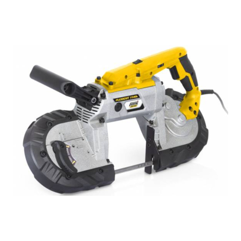
Femi
Femi job FLEXICUT 1140E User manual
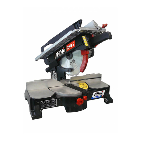
Femi
Femi 280 Specification sheet
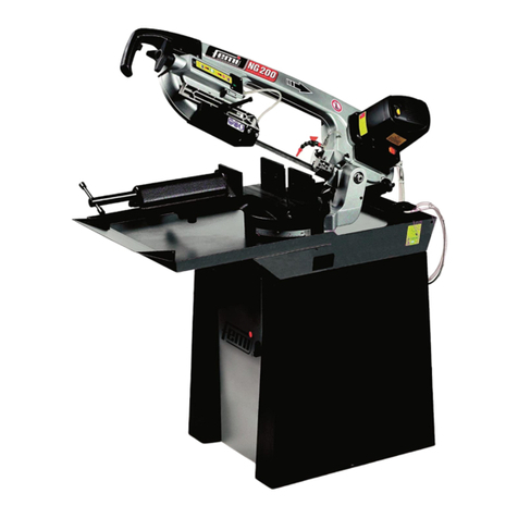
Femi
Femi NG200 Specification sheet

Femi
Femi TR240 User manual

Femi
Femi 2200 Specification sheet
Femi
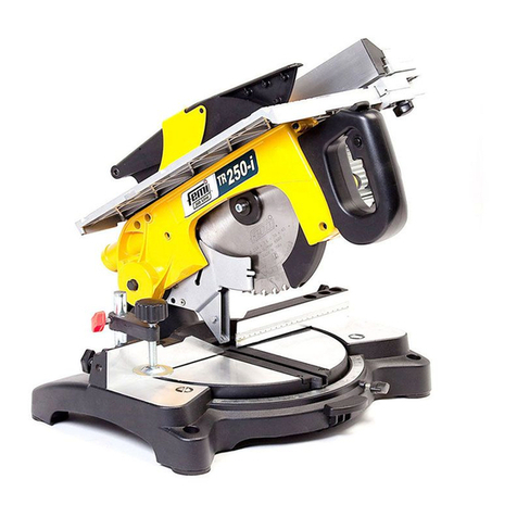
Femi TR 250-i User manual

Femi
Femi 785XL Specification sheet
Femi
Femi N251DA XL User manual

Femi
Femi NG 160 Specification sheet

Femi
Femi 999 Specification sheet
