Femi 2200 Specification sheet

Art.
2200
SPECIAL
ISTRUZIONI PER L’USO E MANUTENZIONE
INSTRUCTIONS FOR USE AND MAINTENANCE
GEBRAUCHSANLEITUNGEN UND WARTUNG
MODE D’EMPLOI ET ENTRETIEN
INSTRUCCIONES PARA EL USO Y MANUTENCION
INSTRUÇÕES DE UTILIZAÇÃO
GEBRUIK- EN ONDERHOUDSAANWIJZINGEN
SEGATRICE A NASTRO
BAND-SAW MACHINE
BANDSÄGEMASCHINE
SCIE A RUBAN
SIERRA DE CINTA
SERRA DE FITA
BANDZAAGMACHINE
CERTIFICATA
CERTIFIED
GEPRÜFT
CERTIFIE
CERTIFICADA
CERTIFICADA
www.femi.it
2200_copertina_FEMI.indd 12200_copertina_FEMI.indd 1 14/10/2008 15.16.1014/10/2008 15.16.10

DICHIARAZIONE DI CONFORMITÁ CE
DEL COSTRUTTORE FEMI S.p.A.
Via Salieri, 33-35 - 40024 Castel San Pietro Terme (BO) - ITALY
Tel. +39-051-941866 - Fax +39-051-6951332 - http://www.femi.it
Dichiara che la: SEGATRICE A NASTRO “2200 SPECIAL”
è conforme alle disposizioni contenute nelle Direttive:
CEE 98/37 - 2004/108 - 2006/95
COMPLIANCE DECLARATION CE
OF THE BUILDER FEMI S.p.A.
Via Salieri, 33-35 - 40024 Castel San Pietro Terme (BO) - ITALY
Tel. +39-051-941866 - Fax +39-051-6951332 - http://www.femi.it
Declare the: BAND-SAW MACHINE “2200 SPECIAL”
is in compliance with the rules contents in the Directives:
CEE 98/37 - 2004/108 - 2006/95
CE ERKLARUNG
DES HERSTELLER FEMI S.p.A.
Via Salieri, 33-35 - 40024 Castel San Pietro Terme (BO) - ITALY
Tel. +39-051-941866 - Fax +39-051-6951332 - http://www.femi.it
Erklart dass: BANDSÄGEMASCHINE “2200 SPECIAL”
ist konform mit der Direktiven:
CEE 98/37 - 2004/108 - 2006/95
DECLARATION DE CONFORMITE CE
DU CONSTRUCTEUR FEMI S.p.A.
Via Salieri, 33-35 - 40024 Castel San Pietro Terme (BO) - ITALY
Tel. +39-051-941866 - Fax +39-051-6951332 - http://www.femi.it
Declare que la: SCIE A RUBAN “2200 SPECIAL”
est conforme aux disposition contenues dans les Directives:
CEE 98/37 - 2004/108 - 2006/95
DECLARATION DE CONFORMIDAD CE
DEL CONSTRUCTOR FEMI S.p.A.
Via Salieri, 33-35 - 40024 Castel San Pietro Terme (BO) - ITALY
Tel. +39-051-941866 - Fax +39-051-6951332 - http://www.femi.it
Declara que la: SIERRA DE CINTA “2200 SPECIAL”
esta conforme a las disposiciones contenide en la Directivas: CEE
98/37 - 2004/108 - 2006/95
DECLARAÇÃO DE CONFORMIDADE CE
DO CONSTRUTTORE FEMI S.p.A.
Via Salieri, 33-35 - 40024 Castel San Pietro Terme (BO) - ITALY
Tel. +39-051-941866 - Fax +39-051-6951332 - http://www.femi.it
Declara que a: SERRA DE FITA “2200 SPECIAL”
suivindo as regras exigidas no contendo da Directivas:
CEE 98/37 - 2004/108 - 2006/95
INDICE/ INDEX / INHALT / INDEX / INDICE / ÍNDICE
ITALIANO (IT) ...................................................................................................................................................................... 1 ÷ 7
ENGLISH (EN) ................................................................................................................................................................... 8 ÷ 14
DEUTSCH (DE)................................................................................................................................................................ 15 ÷ 21
FRANCAIS (ES)............................................................................................................................................................... 22 ÷ 28
ESPANOL (ES) ................................................................................................................................................................ 29 ÷ 35
PORTUGUÊS (PT)........................................................................................................................................................... 36 ÷ 42
15/09/2008
2200_copertina_FEMI.indd 22200_copertina_FEMI.indd 2 14/10/2008 15.16.1314/10/2008 15.16.13

6.90.14.26
NR. 1
TAVOLE RICAMBI - SPARE PARTS - ERSATZTEILE - PIECES DE RECHANGE - REPUESTOS - PEÇAS DE MUDANÇA
POS. COD./KOD. NOTE/MERKE/
NOTES/NOTA/NOTAS
1 5.13.07.96
2 UNI 6592 Ø 6,5x18
3 0.14.70.07
4 UNI5588 M6
5 UNI 5737 M6x20
6 0.14.70.17
7 5.18.25.32
8 5.15.25.94
9 5.15.25.95
10 UNI 5732 M14x70
11 5.13.08.64
12 5.13.79.63
13 UNI 5931 M8x20
14 0.15.26.30
15 UNI 5931 M8x20
16 5.15.26.11
17 5.13.08.63
18 5.15.95.17
19 UNI 6592 Ø14
20 0.14.00.59
21 UNI 5739 M12x50
22 5.17.10.40
23 5.14.20.23
24 5.10.03.34
25 0.14.00.73
26 5.14.20.90
27 5.17.10.35
28 0.15.24.30
29 UNI 6954 P8x9,5
30 5.12.40.33
31 0.12.07.08
POS. COD./KOD. NOTE/MERKE/
NOTES/NOTA/NOTAS
32 UNI 5923 M8x35
33 UNI 5588 M8
34 5.13.37.03
35 7.11.35.24
36 5.87.10.73
37 UNI 6592 Ø16
38 5.18.25.33
39 5.18.25.34
40 5.12.40.56
41 UNI 6592 Ø6
42 5.40.19.35
43 0.40.29.05
44 0.12.40.32
45 UNI 5737 M8x50
46 5.17.10.38
47 0.10.17.16
48 UNI 6592 Ø16
49 0.60.62.03
50 5.13.80.21
51 0.60.63.06
52 5.17.10.39
53 5.06.30.36
54 0.80.23.19
55 5.18.25.17
56 UNI 5933 M8x25
57 5.12.40.60
58 0.60.62.04
59 3.27.73.40
60 5.21.42.24
61 5.13.07.46
POS. COD./KOD. NOTE/MERKE/
NOTES/NOTA/NOTAS
62 5.00.15.62
63 5.08.10.07
64 5.14.20.58
65 5.10.05.05
66 5.12.06.61
67 UNI 5588 M4
68 5.12.20.17
69 5.12.40.30
70 0.06.40.02
71 0.71.15.28
72 0.14.00.99
73 0.08.02.60
74 UNI 6592 Ø16
75 5.06.10.38
76 5.06.60.16
77 0.80.11.01
78 5.18.28.42
79 DIN 7500 M5x10
80 5.14.30.05
81 5.14.20.59
82 5.18.25.23
83 UNI 7687 M4x10
84 0.10.61.20
85 UNI 6592 Ø20
86 5.21.40.26
87 0.15.51.49
88 5.13.07.95
89 UNI 5589 M12
90 0.60.62.04
91 UNI 6954 P7x16
92 0.89.40.07
17
14
19
20
10
11
12
9
8
7
13
6
31
30
32
33
5
4
3
2
1
52
51
50
49
48
47
47
37
16
15
36
19
24
25
26
44
43
33
45
5
21
39
38
34
28
27
23
22
40
42
43
46
53
A
A
35
29
18
4
5
41
Fig. 12
Fig. 3 Fig. 4
Fig. 5 Fig. 6
Fig. 10
Fig. 9
Fig. 8Fig. 7
Fig. 11
A
B
C
C
A
B
CA
B
D
E
D
A
B
B
C
D
AA
B
A
B
C
A
A
CB
D
E
NFig. 1
P
O
Q
M
A
B
CI
H
F
G
D E L
D
N
Fig. 2
cm 90 ÷ 95

IT
1
1.3 TARGHETTE/ETICHETTE DI SICUREZZA
Le targhette/etichette di sicurezza e segnalazioni presenti
sulla macchina, la cui dislocazione è mostrata nella figura
riportata nella controcopertina, sono le seguenti:
1 INTRODUZIONE ALL’USO
Prima di iniziare le lavorazioni con la Vostra segatrice,
leggete attentamente questo manuale di istruzioni, allo
scopo di conoscere la macchina ed i suoi impieghi, e le
eventuali controindicazioni. Conservate con cura questo
manuale: esso fa parte integrante della macchina, e ad
esso dovrete sempre riferirvi per eseguire al meglio e
nelle massime condizioni di sicurezza le operazioni che
in esso sono descritte. Utilizzate la macchina solo ed
esclusivamente per gli impieghi di seguito specificati,
usandola come raccomandato in questo manuale, e non
cercando in alcun modo di manometterla o forzarla, o di
usarla per scopi non adatti.
1.1 SIMBOLOGIA
Non sottovalutare i richiami “ATTENZIONE - CAUTELA”
riportati in questo manuale. Al fine di attirare l’attenzione
e dare messaggi di sicurezza le operazioni pericolose
sono precedute da simboli e note che ne evidenziano
la pericolosità e spiegano come comportarsi per evitare
il pericolo. Questi simboli e note sono di tre categorie
identificate dalle parole:
ATTENZIONE: comportamenti rischiosi che
potrebbero provocare gravi lesioni.
CAUTELA: comportamenti che potrebbero causare
lesioni non gravi o danni alle cose.
NOTE: le note precedute da questo simbolo sono di
carattere tecnico e facilitano le operazioni.
1.2 SICUREZZA E NORMATIVA
Lamacchinaèprogettataecostruitasecondoleprescrizioni
imposte dalle vigenti Direttive Comunitarie:
98/37/CE - 2006/95/CE - 2004/108/CE
Sonoinoltrestaterispettate le norme tecniche di riferimento
relative a questo tipo di prodotto che forniscono garanzia
di conformità alle Direttive sopra citate.
Ladichiarazionedi conformità CE allegata, unita al marchio
CEpostosulprodotto,costituisceelemento fondamentale e
parteintegrantedellamacchina: garantiscono la conformità
del prodotto alle Direttive di sicurezza sopra citate.
INDICE
1 INTRODUZIONE ALL’USO ....................................1
2 INSTALLAZIONE.....................................................2
3 REGOLAZIONI........................................................3
4 UTILIZZAZIONE......................................................4
5 ACCESSORI...........................................................5
6 MANUTENZIONE ...................................................5
7 GUIDAALLA LOCALIZZAZIONE DEI GUASTI.......7
- Indossare i dispositivi di protezione
acustica.
- Indossare maschera o occhiali di
protezioni.
- E’ vietato inserire le mani in questa
zona, utensile in funzione. Pericolo di
trascinamento/taglio.
1.4 TIPO DI IMPIEGO E CONTROINDICAZIONI
Questa macchina e’ stata progettata e realizzata per il
taglio dei metalli.
Essa può tagliare:
• ACCIAI COMUNI (FE 37..)
• ACCIAI SPECIALI (C 40, 18NiCrMo5..)
• ALLUMINIO E SUE LEGHE
• OTTONE
• BRONZO
• TUBI IN ACCIAIO (FE 35, FE 52..)
• PROFILATI IN LAMIERA E ALLUMINIO
Non e’ adatta per il taglio di:
• LEGNO E MATERIE ASSIMILATE
• OSSA E MATERIEASSIMILATE
Perconoscerelecapacita’ditaglio,levelocita’da impiegare
ed i tipi di utensile adatti in base al materiale da tagliare
ed alla sua sezione, consultate i rispettivi capitoli (vedi
indice).
1.5 NORME DI SICUREZZA GENERALI
• Non usate la macchina in luoghi molto umidi o con
presenza di liquidi infiammabili o di gas.
• Non usatela all’aperto, quando le condizioni generali
meteo ed ambiente non lo consentono (es. atmosfere
esplosive, durante un temporale o precipitazioni).
• Non forzate inutilmente la macchina: una pressione di
taglioeccessiva può provocare un rapidodeterioramento
della lama ed un peggioramento delle prestazioni della
macchina in termini di finitura e di precisione del taglio.
• Evitate partenze accidentali: non tenete premuto il
pulsante nell’ impugnatura mentre inserite la spina
nella presa di corrente ed assicuratevi che l’interruttore
generale sia sulla posizione 0.
• Vestitevi adeguatamente: evitate di indossare abiti con
maniche larghe od oggetti, come sciarpe, catene e
bracciali, che potrebbero essere agganciati dalle parti in
movimento.
• Usatesempreidispositivipersonali di protezione: occhiali
antinfortunisticiconformi alle norme, guantidi dimensioni
adatte a quelle della mano, cuffie o inserti auricolari e
cuffie per il contenimento dei capelli, se necessario.
• Usate gli utensili raccomandati in questo manuale,
se volete ottenere dalla vostra segatrice le migliori
prestazioni.
• Fate attenzione al cavo di alimentazione: non utilizzatelo
per scollegare la spina dalla presa di corrente,
salvaguardatelo da spigoli taglienti e non esponetelo ad
elevate temperature.
• Eventualiprolungamentidel cavo di alimentazione devono
essere di tipo omologato e rispondente alle normative di
sicurezza.
• Evitate di utilizzare la macchina se siete in condizioni
psicofisiche precarie o alterate o sotto l’effetto di alcool o
sedativi.
2200_PARTI COMUNI.indd 12200_PARTI COMUNI.indd 1 21/10/2008 15.27.3521/10/2008 15.27.35

IT
2
1.6 NORME DI SICUREZZA PER I RISCHI RESIDUI
ATTENZIONE:
Tenete sempre le mani lontane dalle zone di
lavorazione mentre la macchina e’in movimento;
prima di eseguire qualsiasioperazione di carico e
scarico del pezzo rilasciate il pulsante di marcia
dell’impugnatura.
• Mantenete sempre pulita la zona di taglio e la zona di
carico del liquido refrigerante dai residui di lavorazione.
• Usate sempre la morsa: i pezzi oggetto di taglio devono
sempre essere tenuti fermamente nella morsa.
• Non effettuate alcuna operazione di manutenzione
ordinaria senza prima avere scollegato la spina del cavo
rete dalla presa di corrente.
• Prima di iniziare le lavorazioni controllate che tutte le
protezioni siano integre e posizionate correttamente.
1.7 INFORMAZIONI RELATIVE AL RUMORE E
ALLE VIBRAZIONI
Rumore
Livello sonoro postazione
operatore (a vuoto).............................. Leq = 81,5 dB (A)
Livello sonoro postazione operatore
(a carico).................................................Leq 82,4 dB (A)
Condizioni delle prove a carico:
Tagliotondo di acciaio9SMnPb28, Ø80 mm, allavelocità
di 80 m/min
Potenza Sonora (a vuoto)...................... Lwa 92,6 dB (A)
Potenza Sonora (a carico)..................... Lwa 94,0 dB (A)
Taglio profilato di acciaio 60x60, spessore di 3 mm, alla
velocità di 80 m/min.
Potenza Sonora (a vuoto).......................Lwa 92,6 dB (A)
Potenza Sonora (a carico).....................Lwa 96,2 dB (A)
Le rilevazioni sono state eseguite utilizzando la norma UNI
EN ISO 3746.
Vibrazioni
Il valore medio quadratico ponderato in frequenza, dell’
accelerazione mano braccio, non supera i 2,5 m/sec2.
Le rilevazioni sono state eseguite utilizzando la norma UNI
EN ISO 5349-1 e 5349-2.
I livelli di emissione indicati non sono necessariamente
livellidisicurezza.Puresistendounarelazionetraemissioni
e livelli di esposizione, i valori riportati non possono
essere usati per stabilire la necessità o meno di ulteriori
precauzioni. Esistono altri fattori che influenzano i livelli di
esposizione degli operatori, quali caratteristiche del luogo
di lavoro, presenza di atre sorgenti di rumore, numero di
macchine funzionanti ecc.. Inoltre i livelli di esposizione
possono variare da un paese all’ altro.Tale informazione è
necessaria all’ utilizzatore per fare la migliore valutazione
sui rischi e pericoli derivanti dalle emissioni sonore.
NOTE: E’ comunque raccomandato l’uso dei
mezzi personali di protezione dell’udito , come
cuffie o inserti auricolari.
1.8 INFORMAZIONI SULLA COMPATIBILITA’
ELETTROMAGNETICA
Le recenti Normative Europee sulla sicurezza, ed in
particolare la Direttiva 2004/108/CE, prescrivono che tutte
leapparecchiaturesianodotatedidispositividischermatura
per i radiodisturbi sia da che verso l’ambiente esterno.
Questa macchina è dotata di filtri sia sul motore che
sull’alimentazione che la rendono sicura e conforme alle
prescrizioni. Le prove sono state eseguite secondo le
Norme EN 61000-6-1, EN 61000-6-3, EN 55014-1, EN
55014-2.
1.9 DESCRIZIONE DELLA MACCHINA (Fig. 1)
Nella macchina si possono individuare il corpo macchina
Dcompleto di motore Fe di trasmissione ad ingranaggi;
il collegamento alla parte inferiore è ottenuto tramite il
supporto girevole H. La morsa Odotata di scorrimento
rapido, è interamente costruita in ghisa, mentre la vasca
base N, in acciaio stampato, funge, oltre che da raccolta
per il liquido refrigerante, anche da base di collegamento
con il basamento M (optional). Qui di seguito, trovate un
elencodelle parti principali, alle qualicorrisponde il numero
che lo identifica nella figura.
AImpugnatura di comando
BTensionatore lama
CGuidalama scorrevole
DCorpo macchina
ELama
FMotore
GScatola comandi
HSupporto girevole
IMolla
LPompa circuito refrigerante
MBasamento
NVasca base
OMorsa
PAzionatore morsa
QLeva scorrimento rapido morsa
PESO ..........................140 Kg. (compreso il basamento)
DIMENSIONI .......................cm 575 x 670 x H 720 nella
..............................configurazione di massimo ingombro.
DIMENSIONI IMBALLO ............cm 780 x 1240 x H 1080
2 INSTALLAZIONE
2.1 RIMOZIONE DELL’IMBALLO
Lamacchina viene spedita all’interno diuna scatola adatta
aquestoscopo. Occorre pertanto rimuovere completamente
tale imballaggio con l’utilizzo di strumenti idonei, facendo
attenzioneanon danneggiare alcuna parte della macchina.
Per lo smaltimento dell’imballaggio, vedi capitolo 6.4.
2.2 MOVIMENTAZIONE E TRASPORTO (Fig. 2)
La macchina ha un peso rilevante e deve essere
movimentataesclusivamentetramitemezzidisollevamento
adatti.
ATTENZIONE:Non tentate di movimentare o
sollevare la macchina a mano anche in più
persone.
ATTENZIONE: Le operazioni di imbragatura,
spostamento e sollevamento tramite carrello
elevatore o paranco descritte in questo manuale
devono essere effettuate da personale formato a
tale scopo ed in possesso dei requisiti necessari
(98/37/CEE).
2200_PARTI COMUNI.indd 22200_PARTI COMUNI.indd 2 21/10/2008 15.27.3921/10/2008 15.27.39

IT
3
Per spostare la macchina quando è ancora nel suo imballo
utilizzateun carrello elevatore inserendo le dueforche negli
appositi spazi sotto alla pedana di appoggio.
Movimentatelamacchina con cautela facendo attenzionea
movimentibruschichepotrebberoportareallosbilanciamento
del carico e conseguente caduta.
Persepararela macchina dalla pedana dopo avere rimosso
l’imballaggio svitate le viti di fissaggio, avendo cura di
conservarle nel caso si dovesse trasportare la macchina
per lunghi tragitti.
Per movimentare la macchina dopo la separazione della
pedana, occorre come prima cosa imbragarla con catene,
funi o bretelle di resistenza adeguata, facendole passare
attraverso i grilli in dotazione.
La macchina va poi sollevata utilizzando un paranco di
portata adeguata oppure un altro mezzo di sollevamento
adeguato allo scopo.
ATTENZIONE: E’ vietato sollevare la macchina
tramite il corpo D (Fig. 1)
ATTENZIONE: Prima di sollevare la macchina,
assicuratevi che il corpo sia in posizione
abbassata e vincolato al resto della struttura
tramite corde o altro sistema di bloccaggio come
indicato in Fig. 2.
2.3 COLLEGAMENTO ELETTRICO (Fig. 3)
Controllatechel’impiantoretesulquale inserite la macchina
siacollegato a terra come previstodalle normedi sicurezza
vigenti, e che la presa di corrente sia in buono stato.
Si ricorda all’ utilizzatore che a monte dell’ impianto rete
deve essere presente una protezione magnetotermica
atta a salvaguardare tutti i conduttori dai corto circuiti e
dai sovraccarichi.
Taleprotezionedovràesseresceltainbaseallecaratteristiche
elettriche della macchina riportate sul motore.
Se dovesse verificarsi una mancanza di tensione
nell’impianto di rete, potete attendere che si ristabilisca il
collegamento senza che si creino condizioni di pericolo:
l’interruttoreD (Fig. 3). includeinfatti unafunzione di reset,
che impedisce il riavviamento automatico della macchina.
Il motore della vostra segatrice è dotato di disgiuntore
termico di protezione, che interrompe l’alimentazione
quando la temperatura degli avvolgimenti diventa troppo
elevata.
Nel caso di interruzione, attendere il normale ripristino.
2.4
POSIZIONAMENTO/POSTO DI LAVORO (Fig. 5)
Posizionate la macchina movimentandola come descritto
al paragrafo 2.2., su un banco sufficientemente piano, in
modo che il liquido refrigerante possa regolarmente rifluire
nell’apposita vasca di raccolta durante le operazioni di
taglio.
Per eseguire le lavorazioni tenendo conto dei criteri
ergonomici, l’altezza ideale deve essere quella che vi
consente di posizionare il piano della morsa tra i 90 ed i 95
centimetri da terra (Fig. 2).
A questo punto, tagliate la reggetta che tiene il corpo
in posizione abbassata, e togliete il tappo in legno che
protegge la macchina durante il trasporto.
CAUTELA: Abbiate cura di posizionare la
macchina in una zona di lavoro adeguata sia
come condizioni ambiente che come luminosita’:
ricordate sempre che le condizioni generali
dell’ambiente di lavoro sono fondamentali nella
prevenzione degli infortuni.
Sollevateorail corpo macchina, ed inseritel’occhiello della
mollaAnella sua sede sul pernoBper evitare lafuoriuscita
della molla.
3 REGOLAZIONI
3.1 TENSIONE DELLA LAMA (Fig. 4)
Ruotateinsensoorario il volantino Bfinche’la spia luminosa
verde C si accende.
ATTENZIONE: Il tensionatore è dotato di
microswitch di sicurezza, che impedisce il
funzionamento della macchina finchè la lama
non viene tensionata correttamente.
3.2 ARRESTO BARRA (OPTIONAL) (Fig. 6)
Se dovete effettuare piu’ tagli di pezzi tutti della stessa
lunghezza,usatel’arresto barra in dotazione, evitando cosi’
di rifare tutte le volte la stessa misura.
Primadi effettuarelaregolazione, posizionate l’interruttore
generale B(Fig. 8) sulla posizione 0 (zero).
Avvitatel’asta Anel forodella base e bloccatela coldado B;
allentateil volantino Ce posizionate ilfermo Dalla distanza
necessaria dalla lama; ribloccate il volantino C.
3.3 ANGOLAZIONE DI TAGLIO (Fig. 7)
La macchina può effettuare tagli con angolazioni variabili
da 0° a 60°.
Per sbloccare la rotazione del corpo, allentate la maniglia
Asul supporto girevole.
Fateruotareilcorpomacchina verso sinistra fino all’arresto,
che avviene per taratura di fabbrica posizionato sui 60°.
Per avere l’arresto tarato a 45°, allentate il volantino E,
tiratela staffaDfino a fine corsa, corrispondentecon la fine
dell’asola della staffa stessa, e ribloccate il volantino E; in
questo modo, quando ruotate il corpo macchina a sinistra,
l’arresto avviene automaticamente a 45°.
Perriportare l’arresto a 60°,compiete la stessaoperazione
descritta in precedenza, riposizionando la staffa Dnella
posizione originale.
Per tutte le altre angolazioni intermedie, fate conicidere
l’indice Cdel supporto girevole con la corrispondente
posizione sulla targhetta B.
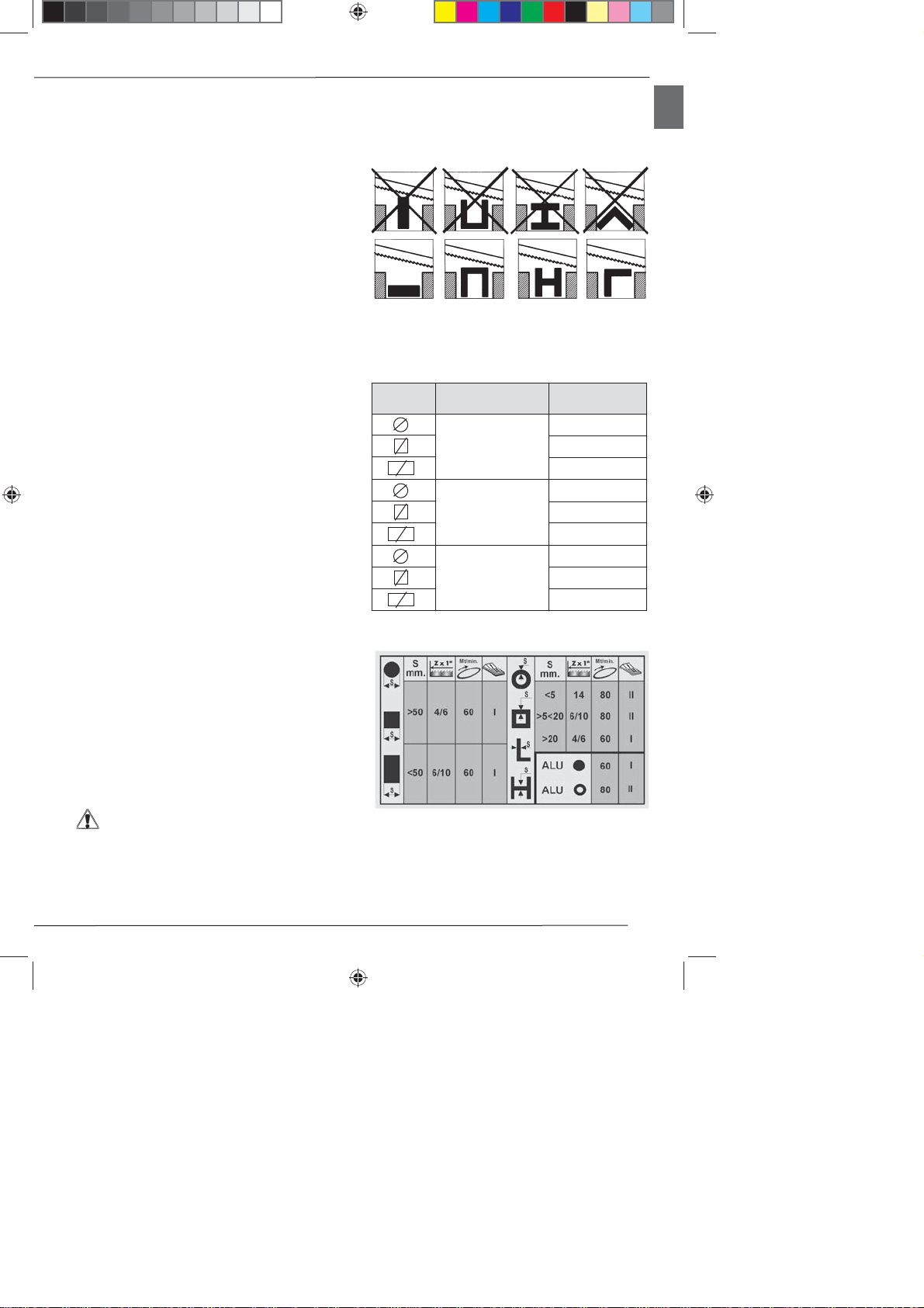
3.4 VELOCITA’ DI TAGLIO (Fig. 3)
In base al tipo di materiale ed alla sua sezione (vedi
TABELLA DI TAGLIO) potete selezionare due diverse
velocità di taglio (60 oppure 80 m./min.) tramite il
commutatore N.
2200_PARTI COMUNI.indd 32200_PARTI COMUNI.indd 3 21/10/2008 15.27.4021/10/2008 15.27.40

IT
4
3.5 GUIDALAMA SCORREVOLE (Fig. 4)
Il guidalama scorrevole Dcon protezioni integrate di cui e’
dotata la vostra segatrice, vi consente di effettuare il taglio
mantenendo sempre guidata la parte di lama necessaria,
e di proteggere integralmente quella non utilizzata nella
lavorazione. Allentate la maniglia Ee fate scorrere il
guidalama Din modo da avvicinarlo o allontanarlo dal
pezzo da tagliare, come indicato in figura.
ATTENZIONE: Se questa regolazione non viene
effettuata, rimane scoperta una porzione di lama
non necessaria alla lavorazione, che puo’ creare
un rischio residuo di contatto con essa, oltre a
pregiudicare la qualita’ del taglio.
3.6 CUSCINETTI GUIDALAMA (Fig. 9)
Per facilitare la sostituzione della lama e tenerla sempre
guidata al meglio, i guidalama esterni Adella segatrice
sono eccentrici e regolabili. Essi devono sempre essere
posizionati a leggero contatto con la lama, in modo da
ruotare al passaggio della stessa, ma non completamente
bloccati.Per avvicinare o allontanare iguidalama eccentrici
è sufficiente ruotare leggermente con chiave mm. 10 la
testa delle viti B.
4 UTILIZZAZIONE
4.1 REFRIGERAZIONE DELLA LAMA (Fig. 11)
La vostra segatrice è dotata di impianto di refrigerazione
automatica della lama, comandato da un elettropompa
Aposizionata all’interno della vasca. Prima di mettere
in funzione la macchina, preparate 12 litri di emulsione
acqua olio al 10%, versando la quantita’ di olio necessaria
direttamente nell’acqua, che deve avere una temperatura
noninferioreai10gradi. Agitateefficaciementeilcontenuto,
e versatelo direttamente nel serbatoio della pompa B.
Nonfatefunzionarelamacchina senza il liquido refrigerante
per evitare di danneggiare la lama.
Usateoliospecificatamenteindicatoper la preparazione dei
refrigeranti (vedi TABELLA DEGLI OLI seguente):
ATTENZIONE: Prima di azionare la macchina
controllaresempreche il getto della lubrificazione
sia rivolto verso la lama e che il suo rubinetto
non sia eccessivamente aperto.
4.2 FUNZIONAMENTO (Fig. 3)
Commutate l’interruttore generale D sulla posizione 1: in
questo modo l’interruttore si accende, e la macchina è
pronta per funzionare.
ATTENZIONE:Prima di iniziare ogni operazione
di taglio, accertatevi mediante un controllo a
vista che tutte le protezioni siano integre ed in
posizione adeguata.
Una volta eseguite tutte le procedure e le operazioni finqui
descritte, potete iniziare le lavorazioni.
Per effettuare il taglio, disponetevi di fronte alla macchina,
ed impugnate con la mano destra l’impugnatura.
ATTENZIONE:Tenete la mano sinistra sempre
lontana dalla zona di taglio e non cercate in alcun
modo di raggiungerla durante le operazioni di
taglio.
Premete con l’indice della mano destra il pulsante di
marcia A (Fig. 4) ed abbassate gradualmente il corpo
fino a mettere a contatto dolcemente la lama con il pezzo
da tagliare.
Iniziate ora ad applicare uno sforzo progressivo sul pezzo,
e completate il taglio.
ATTENZIONE:Fra un taglio ed un altro, nella fase
di posizionomento del pezzo, rilasciate sempre il
pulsanteA, non cercate dibloccarlo o di alterarne
in alcun modo le caratteristiche funzionali.
Se dopo numerosi tagli consecutivi la macchina
dovesse improvvisamente fermarsi, non allarmatevi:
è intervenuto il termoprotettore del motore, che
toglie l’alimentazione quando la temperatura degli
avvolgimenti raggiunge la soglia limite definita dalla
classe di isolamento, evitando danni al motore.
In questo caso, rilasciate il pulsante A ed attendete
il ripristino automatico, che ritorna in genere dopo
qualche minuto.
4.3 RODAGGIO DELLA LAMA
Perottenerelemiglioriprestazioni, le lame bimetalliche che
corredanola vostra segatrice devono essere sottopostead
una breve procedura di rodaggio.
Occorrepercio’effettuareiprimidueotre tagli possibilmente
su un pezzo pieno D. 70 - 80 mm., esercitando sul pezzo
una pressione molto lieve, incrementandola man mano
nei tagli successivi.
Per rendervi conto di quale sia la pressione giusta nelle
normali condizioni di utilizzo definite da questo manuale
(vedi tabella di taglio), considerate ad esempio che il
primo taglio su un acciaio (es. C40) pieno D. 80 mm. deve
essere effettuato in circa 5 minuti; a rodaggio ultimato, lo
stesso pezzo puo’ essere tagliato tranquillamente in circa
2 minuti.
Un rodaggio ben eseguito, comporta una migliore qualita’
del taglio, sia come finitura che come precisione, ed una
maggiore durata della lama.
AGIP OXALIS
CASTROL SUPER
CHEVRON EP
ESSO KUTWELL
MOBIL SOLVAC
SHELL DROMUS
TOTAL LACTUGA
IP UTENS
TABELLA DEGLI OLI
MARCA TIPO OLIO
2200_PARTI COMUNI.indd 42200_PARTI COMUNI.indd 4 21/10/2008 15.27.4021/10/2008 15.27.40

IT
5
4.4 SOSTITUZIONE DELLA LAMA
Quando effettuate questa operazione, indossate sempre
i guanti di protezione, al fine di evitare contatti con i denti
della lama.
• rassicuratevi che l’interruttore generale B(Fig. 3)/(Fig.
8) sia sulla posizione 0;
• ruotate il volantino B (Fig. 4) in senso antiorario fino a
che la spia del tensionatore si spegne;
• fate scorrere i guidalama D (Fig. 4) fino a fine corsa
allentando le maniglie E (Fig. 4);
• rimuovete il carter di protezione allentando le viti A (Fig.
12) e sollevandolo dalla sede B (Fig. 12);
• estraete la lama dalle guide e dai volani;
• inserite la lama nuova prima tra le guide, poi sui volani;
• rimettete in tensione la lama.
Controllate che il dorso della lama vada a posizionarsi sul
cuscinetto reggispinta A(Fig. 10) situato all’interno della
parte superiore del corpo macchina. Se cosi’ non fosse,
allentate leggermente la lama e riconducetela nella giusta
posizione.
• rimontate il carter di protezione.
• serrare le viti
A questo punto, azionate il pulsante A(Fig. 4) a piccoli
impulsi, in modo da far posizionare correttamente la lama
sulle pulegge.
4.5 USO DELLA MORSA (Fig. 8)
La morsa della segatrice è dotata di scorrimento rapido, al
fine di permettere l’avvicinamento del corsoio al pezzo da
bloccare in modo pratico e veloce.
Per bloccare il pezzo da tagliare in morsa:
• disponetevi di fronte alla macchina;
• azionate la leva Averso il pezzo da tagliare, sbloccando
il corsoio B;
• spingeteilcorsoioverso il pezzo da tagliare, avvicinandolo
fino a qualche millimetro da esso;
• bloccate la leva A, spingendola verso di voi;
• ruotatelalevaCin sensoorario,bloccando definitivamente
il pezzo tra le ganasce.
Sedovetetagliare più pezzi dalla stessa barra,è sufficiente
sbloccare e successivamente ribloccare la morsa tramite
la leva C.
Seinvecedovete cambiare barra, prima sbloccate la morsa
ruotando in senso antiorario la leva Ce successivamente
azionate la leva Aallontanando il corsoio dal pezzo.
4.6 POSIZIONAMENTO DEL PEZZO IN MORSA
(Fig. 8)
Ipezzida tagliare vanno inseriti direttamente fra leganasce
D, senza interposizione di altri oggetti.
ATTENZIONE: Non tenete mai i pezzi da tagliare
in mano.
Quando il taglio riguarda i profilati, piatti o sagome
particolari, fate riferimento agli esempi di figura.
Se lo spessore del profilato dovesse essere molto sottile,
perevitareilsuoschiacciamento tra le ganasce della morsa,
èmeglioinserire all’interno del profilato stesso unasagoma
che ne copi il profilo.
4.7 CAPACITA’ DI TAGLIO
Latabelladiseguitoriportataspecificale capacita’di taglio a
90,45e 60 gradi ottenibili nelle normali condizionidi utilizzo
descritteinquestomanuale,e senza interposizione di alcun
altro oggetto fra le ganasce della morsa.
4.8 TABELLA DI TAGLIO
90°
45°
60°
170
170 x 170
190 x 130
110
110 x 110
150 x 110
75
75 x 75
100 x 75
Angolazione Capacità di taglio
(mm)
Sezione
2200_PARTI COMUNI.indd 52200_PARTI COMUNI.indd 5 21/10/2008 15.27.4021/10/2008 15.27.40

IT
6
5 ACCESSORI
5.1 SCELTA DELLA LAMA
La vostra segatrice è corredata di lama bimetallica mm.
2140 x 19 x 0,9 con dentatura variabile 6/10 denti per
pollice, che copre gran parte dei tagli possibili con questa
macchina.Perleesigenzeparticolari(vediTabelladi taglio),
ad esempio per il taglio di grosse sezioni piene oppure di
profilati o angolari di piccolo spessore, sono disponibili
anche lame con dentatura 4/6oppure 14 denti per pollice.
MATERIALE: .......M42 (acciaio per molle + acciaio HSS)
SVILUPPO:........................................................mm 2140
ALTEZZA : ............................................................mm 19
SPESSORE : .......................................................mm 0,9
DENTATURA: ............................................standard 6/10
................................................................optional 4/6 - 14
6 MANUTENZIONE
6.1 INTERVENTI DI MANUTENZIONE ORDINARIA
Lenormalioperazionidimanutenzioneordinaria,effettuabili
anche da personale non specializzato, sono tutte descritte
nei paragrafiprecedenti e nel presente.
ATTENZIONE: Prima di effettuare qualsiasi
operazione di manutenzione, disinserite la spina
elettrica della macchina dalla presa di corrente.
ATTENZIONE: Durante le operazioni di
manutenzione, indossate sempre, per quanto
possibile, i mezzipersonali di protezione (occhiali
antinfortunistici e guanti di dimensioni adatte).
AD OGNI UTILIZZO
• Rimuovete i trucioli residui di lavorazione ogni qualvolta
si renda necessario, intervenendo nella zona di taglio e
sui guidalama. E’ consigliato l’uso di un pennello o di un
aspiratore.
ATTENZIONE: E’assolutamente vietato l’uso di
aria compressa !!!
• Verificateche lapompapeschiregolarmentedal serbatoio,
controllandoche il liquido refrigerante escaregolarmente
da entrambi i distributori posti sui guidalama.
PERIODICHE SETTIMANALI
• Lubrificare le slitte del guidalama scorrevole e del
supporto girevole e la madrevite della morsa.
• Rimuovere i trucioli dalla zona del filtro di raccolta del
liquido refrigerante.
• Pulire le placchette guidalama con un pennello.
• Verificare l’integrità di tutte le protezioni della macchina
ed il corretto funzionamento del pulsante di marcia.
• Se non utilizzate la segatrice per lungo tempo, ripulitela
e mettetela possibilimente in un luogo privo di umidità.
E’ buona norma, in questi casi, allentare la lama per non
mantenerla inutilmente in tensione.
6.2 SOSTITUZIONE DEL LIQUIDO REFRIGERANTE
L’emulsione refrigerante va sostituita ogni 500 ore.
• Togliete alimentazione alla macchina disinserendo la
spina dalla presa di corrente.
• Vuotate il serbatoio della pompa tramite il tappo C(Fig.
11), rimuovendo anche gli eventuali trucioli presenti al
suo interno.
• Preparate la nuova emulsione come specificato al punto
4.1 e versatela nel serbatoio, facendo attenzione a non
disperderla nell’ambiente.
• Per lo smaltimento dell’emulsione esausta, vedi punto
6.4.
6.3 ASSISTENZA
Nel caso di riparazione in garanzia, dovete sempre
presentare assieme alla macchina la ricevuta/fattura di
acquisto.
L’assenza di tale certificato invalida la garanzia applicata
alla macchina.
Nelcasosia necessario l’intervento di personalequalificato
per operazioni di manutenzione straordinaria, oppure
nel caso di riparazioni sia in regime di garanzia che
successivamente, rivolgetevi sempre ad un centro di
assistenzaautorizzato,oppure al rivenditore presso il quale
avete acquistato la macchina, se nella vostra regione non
e’ presente il centro di assistenza.
Quando contattate l’assistenza o il rivenditore, ricordate
sempredicomunicareladata di acquisto della macchina ed
il numero di matricola punzonato sulla targhetta CE.
Per l’ordinativo dei pezzi di ricambio, è sempre necessario
comunicare al Centro di Assistenza il modello della
macchina, il suo numero di matricola ed il codice del
componente indicato nelle tavole ricambi.
6.4 SMALTIMENTO MACCHINA, IMBALLAGGIO
SMALTIMENTO MACCHINA, IMBALLAGGIO
INFORMAZIONE AGLI UTENTI
Ai sensi dell’art. 13 del Decreto Legislativo 25
luglio 2005, n. 151 “Attuazione delle Direttive
2002/95/CE, 2002/96/CE e 2003/108/CE,
relative alla riduzione dell’uso di sostanze pericolose nelle
apparecchiature elettriche ed elettroniche, nonché allo
smaltimento dei rifiuti”, si precisa quanto segue:
• Il simbolo del cassonetto barrato riportato
sull’apparecchiatura o sulla confezione indica che il
prodottoallafinedellapropriavitautiledeveessereraccolto
separatamente dagli altri rifiuti.
• L’utente dovrà, pertanto conferire l’apparecchiatura
giunta a fine vita agli idonei centri di raccolta
differenziatadei rifiutielettroniciedelettrotecnici,oppure
riconsegnarla al rivenditore al momento dell’acquisto
di una nuova apparecchiatura di tipo equivalente, in
ragione di uno a uno.
2200_PARTI COMUNI.indd 62200_PARTI COMUNI.indd 6 21/10/2008 15.27.4021/10/2008 15.27.40

IT
7
• L’adeguata raccolta differenziata per l’avvio successivo
dell’apparecchiatura dismessa al riciclaggio, al
trattamento e allo smaltimento ambientalmente
compatibile contribuisce ad evitare possibili effetti
negativi sull’ambiente e sulla salute e favorisce il
reimpiego e/o riciclo dei materiali di cui è composta
l’apparecchiatura.
Motore, cavo rete o spina difettosi.
Fusibili quadro elettrico bruciati.
Manca tensione nell’impianto di
rete.
È intervenuto il termoprotettore
del motore.
Surriscaldamento del motore.
Sovraccaricodel motore causato da
eccessiva pressione di taglio.
Guasto del motore.
La taratura dei fermi D(punto 3.3)
non è esatta.
Pressione di taglio eccessiva (su
tubi e profilati).
Dentatura della lama non corretta in
relazione al pezzo da tagliare.
Velocità di taglio non corretta in
relazione al pezzo da tagliare.
Regolazione non corretta dei
guidalama eccentrici e scorrevole.
Errato posizionamento del pezzo
in morsa.
Lalamaèconsumataoppuranonha
dentatura adatta allo spessore del
pezzo che state tagliando.
Eccessiva pressione di taglio.
Regolazione non corretta dei
guidalama eccentrici.
Il motore non funziona.
Intervento
del termoprotettore.
Imprecisione dell’angolo
di taglio a 90°-60 -45°.
Imprecisione nello
squadro del taglio.
Lafinituradeltagliorisulta
grezza o ondulata.
La lama tende ad uscire
dalle guide.
Fate controllare la macchina da personale
specializzato; non tentate di riparare il motore da
soli.
Controllate l’integrità dei fusibili e sostituiteli se
necessario.
Controllate la presenza di tensione nell’impianto
di rete.
Attendete il normale ripristino del termoprotettore
(alcuni minuti) rilasciando il pulsante di marcia.
Controllate che le prese di aereazione del motore
siano libere da ostacoli.
Eseguite il taglio con la giusta pressione sul
pezzo.
Fate controllare la macchina da personale
specializzato; non tentate di riparare il motore
da soli.
Effettuate la taratura allentando le viti di fissaggio e
riposizionando i fermi.
Diminuite la pressione di taglio.
Controllateiparametriditaglio (dentatura della lama,
velocità di taglio) nella tabella di taglio (punto 4.8).
Controllate la regolazione dei guidalama (punti
3.5 e 3.6).
Controllate il posizionamento ed il serraggio del
pezzo nella morsa (punto 4.6).
Controllateiparametriditaglio (dentatura della lama,
velocità di taglio) nella tabella di taglio (punto 4.8).
Diminuite la pressione di taglio.
Controllate la regolazione dei guidalama eccentrici
(punto 3.6).
PROBLEMA PROBABILE CAUSA RIMEDIO SUGGERITO
7 GUIDA ALLA LOCALIZZAZIONE DEI GUASTI
ATTENZIONE: Lo smaltimento abusivo del
prodotto da parte dell’utente comporta
l’applicazione delle sanzioni amministrative
previste dalla
2200_PARTI COMUNI.indd 72200_PARTI COMUNI.indd 7 21/10/2008 15.27.4121/10/2008 15.27.41

EN
8
1.3 SAFETY PLATES/LABELS
The safety plates/labels and indicators present on the
machine, the location of which is shown in the Figure on
the inside cover, are as follows:
INICE
1 INTRODUCTION TO USE.......................................8
2 INSTALLATION.........................................................9
3 ADJUSTMENT........................................................10
4 USE ........................................................................11
5 ACCESSORIES......................................................12
6 MAINTENANCE......................................................12
7 TROUBLESHOOTING............................................14
1 INTRODUCTION TO USE
Before starting work with your sawing machine, carefully
read this instructions manual so that you are familiar with
the machine and its uses and where it should not be used.
Keep this manual in a safe place. It is an integral part of the
machine and should be used for reference in operating the
machine correctly and in the proper safety conditions.
Usethemachine only and exclusively for the usesspecified
below,asrecommendedin this manual.Themachineshould
not in any way be tampered with, or forced, or used for
unsuitable purposes.
1.1 CONVENTIONAL SYMBOLS
Never underestimate the warnings “ATTENTION -
CAUTION” given in this manual. In order to draw the user’s
attention and to preserve safety, hazardous operation are
preceded by symbols and notes that point out the danger
andexplainhowtobehavetoavoidanyrisk.These symbols
and notes are divided in three categories, identified by the
following words:
WARNING: dangerous-behavioursthat couldcause
serious injuries.
CAUTION:behavioursthatcouldcauseslightinjuries
or damages to things.
NOTE: the notes preceded by this symbols are
technical and are aimed at making operations
easier.
1.2 SAFETY AND RULES
The machine was designed and built according to the
Community Directives in force 98/37/CE - 2006/95/CE -
2004/108/CE.
Moreover, all technical standards relating to this type of
product have been complied with which provide warranty
of compliance with above mentioned directives.
The enclosed CE declaration of conformity together with
the CE brand on the product essentially comprise and are
an integral part of the machine : both guarantee product
conformity with the aforsaid safety Directives.
- Wear noise protection devices.
- Wear safety masks or goggles.
- Do not insert the hands in this area with
the tool operating. Danger of dragging/
cutting.
1.4 RECOMMENDED AND NOT RECOMMENDED
USAGE
Thismachinehasbeen designed and developed for cutting
metals.
It can cut:
• COMMON STEELS (FE 37...)
• SPECIAL STEELS (C 40, 18NiCrMo5...)
• ALUMINIUM AND ITS ALLOYS
• BRASS
• BRONZE
• STEEL TUBING (FE 35, FE 52...)
• PROFILED SECTIONS IN SHEET METAL AND
ALUMINIUM
It is not suitable for cutting:
• WOOD AND SIMILAR MATERIALS
• BONE AND SIMILAR MATERIALS
Consult the relative sections for cutting capacities, the
speeds to use and the type of tools for use according to the
material to be cut and its section. (See list of contents).
1.5 STANDARD SAFETY PROCEDURS
• Do not use the machine in very damp places or in the
presence of inflammable liquids or gases.
• Do not use it in the open air when general weather and
environmentalconditionsare unfavourable (eg. explosive
atmospheres, during a storm or rain).
• Do not force the machine unnecessarily : excessive
cutting pressure could cause rapid wear to the blade and
negatively influence the performance of the machine in
terms of finishes and cutting precision.
• Avoid starting of the machine by accident : do not keep
the button in the handgrip pressed when you plug into
the mains and check that the main switch is in position
0 (zero).
• Wear suitable clothes, without wide sleeves or articles
such as scarves, chains and bracelets which could get
caught in the moving parts.
• Always use personal protection devices: protective
goggles as recommended by safety standards, gloves
of the right size, headphones or earplugs, and hairnets if
necessary.
• Use the tools recommended in this manual if you want
to achieve the best performance from your sawing
machine.
• Do not use the power supply cable to disconnect the plug
form the outlet. Protect it from sharp edges and do not
expose it to high temperatures.
• Any power cable extensions must be type approved abd
comply with safety standards.
• Avoidusing the machine if yourpsycho-physical condition
are precarious or upset or under the effects of alcohol or
sedatives.
2200_PARTI COMUNI.indd 82200_PARTI COMUNI.indd 8 21/10/2008 15.27.4121/10/2008 15.27.41

EN
9
This machine is equipped with filters both on the motor and
onthe power supply through whichthe machine issafe and
in compliance with above regulations.
Tests were carried out according to 61000-6-1, EN
61000-6-3, EN 55014-1, EN 55014-2 regulations.
1.9 DESCRIPTION OF THE MACHINE (Fig. 1)
The machine consists of a machine body Dcomplete with
motor Fand gear transmission. Connection to the bottom
is obtained by means of a rotating support H.
The quick sliding chuck Ois completely made up of cast
iron while the basic tank in pressed steel for the collection
of the coolant serves also as connecting base Nwith the
machine bed M (optional).
Here is a list of the main parts with the number indicating
it in the drawing.
ACommand grip
BBlade tensioning device
CSliding blade guide
DMachine body
EBlade
FMotor
GControl box
HSwivel support
ISpring
LCooling liquid pump
MColumn (optional)
NTank-base
OVice
PClamp drive
QVice speed-slide drive
WEIGHT ...............................140 kg. Including bedframe
SIZE..............................................cm 575 x 670 x H 720
....................................... in maximum overall dimensions.
PACKAGING SIZE .....................cm 780 x 1240 x H 1080
2 INSTALLATION
2.1 REMOVING THE PACKING
The machine is delivered inside a box suitable for the
purpose.
Therefore, the packing must be removed completely by
means of suitable tools and care must be take in order to
avoid damage to any part of the machine.
For packing disposal, please refer to 6.4 point.
2.2 HANDLING AND TRANSPORTION (Fig. 2)
The machine and must be moved only using suitable lifting
devices.
WARNING: Do not try to move or lift the machine
by hand even if more people are present.
WARNING: The operations described in this
manual relative to sling, transport and lifting
by means of a fork lift or hoist must be carried
out only by skilled and qualified personnel
(EEC/98/37).
1.6 SAFETY PROCEDURS FOR FURTHER RISK
WARNING: Always keep hands away from the
working areas while the machine is moving:
before loading or unloading the part, release the
run button on the hand grip.
• Always keep processing residues away from the cutting
area.
• Always use the clamp. The parts to be cut must always
be held firmly in the clamp.
• Before carrying out any maintenance work, always
disconnect the power cable for the mains.
• Check that all safety guards are sound and positioned
correctly before starting any work.
1.7 INFORMATION CONCERNING NOISE AND
VIBRATION LEVELS
Noise
Noise level at the operator’s work
position (without load)............................. Leq 81.5 dB (A)
Noise level at the operator’s
work position (with load)........................... Leq 82.4 dB(A)
Test conditions when working with load:
Cutting of 80 mm dia. barstock in 9SMnPb28 steel at
speed of 80 m/min
Sound power (without load)....................Lwa 92.6 dB (A)
Sound power (with load)..........................Lwa 94.0 dB (A)
Cutting of 60x60 steel profile with 3 mm wall thickness
at speed of 80 m/min.
Sound power (without load).....................Lwa 92.6 dB (A)
Sound power (with load)..........................Lwa 96.2 dB (A)
The measurements were carried out in accordance with
standard UNI EN ISO 3746.
Vibration
Meanfrequency-weightedhand-armaccelerationvibration
exposure does not exceed 2.5 m/s².
The measurements were carried out in accordance with
standards UNI EN ISO 5349-1 and 5349-2.
The emission levels indicated are not necessarily safety
levels. Although there is a relationship between the
emissions and exposure levels, the values shown cannot
be used for establishing the need for further precautions.
There are other factors which influence the exposure
levels of operators, such as the features of the work place,
presence of other sources of noise, number of machines
running, etc.
The exposure levels may also vary between countries.
This information is necessary for the user for better
evaluation of the risks and hazards deriving from noise.
NOTE: Personal hearing protection should be
used, such as headphones or earplugs.
1.8 INFORMATION ABOUT ELECTROMAGNETIC
COMPATIBILITY
The european regulations on safety and in particular
the EEC directive 2004/108 contemplate that all the
equipmentbeequippedwithshieldingdevices against radio
interferences both from and towards the outside.
2200_PARTI COMUNI.indd 92200_PARTI COMUNI.indd 9 21/10/2008 15.27.4121/10/2008 15.27.41

EN
10
To move the machine while it is still inside the packing, use
a fork lift by inserting the two forks in the rooms provided
under the bearing board
Move the machine carefully and avoid sudden movements
which could unbalance the load and make it drop.
Toremovethemachinefromtheplate after packing removal,
loosenthe fixing screws but keepthem shouldthe machine
be transported for long stretches.
Totransportthemachine afterfreeingitfrom the plate,secure
it with resistant chains, ropes or braces, by passingthem
through the the eyebolts provided.
Then the machine must be lifted using a hoist of adequate
capacity or through another means suitable for this
purpose.
WARNING: Do not lift the machine by the body D
(Fig. 1).
WARNING: Before lifting the machine, check that
the body is lowered and secured to the rest of
the structure by means of ropes or other claming
means as shown in Fig. 2
2.3 ELECTRICAL CONNECTIONS (Fig. 3)
Check that the mains to which the machine is connected is
earthed in accordance with current safety regulations and
that the power point is in good condition.
Remember that there should be a magnetothermic
protective device fitted upstream of the mains to protect all
the conductors from short circuits and overloads.
This protective device should be selected according to the
electrical features of the machine stated on the motor.
In case of power failure in mains, while you wait for power
to be restored there is no danger hazard may arise: in
fact, the main switch D (Fig. 3) is also equipped with a
reset function which prevents the machine from restarting
automatically.
The motor of your sawing machine is equipped with a
protective heat circuit breaker which interrupts the power
supply when the temperature of the coils rises too high.
When the power supply is interrupted, wait for normal
reset.
2.4 POSITION/WORK STATION (Fig. 5)
Position the machine by moving it as described in
paragraph 2.2 on to a sufficiently level bench, in such a
way that the coolant can reflow in the collecting tank during
the cutting operations.
Taking the ergonomic criteria into consideration, the ideal
height shall be that which enables you to position the
table between 90 and 95 centimetres from the floor (see
Fig. 2).
Now, cut the strap which holds the body lowered and
remove the wooden cap which protects the machine
while in transit.
CAUTION: Make sure that the machine is placed
in a working area with suitable environmental
conditions and lighting. The general conditions
of the working environment are of fundamental
importance for accident prevention.
Now lift the machine body and fit the eye of spring A into
its location on pin B to prevent the spring from being
expelled.
3 ADJUSTING
3.1 TENSION OF THE BLADE (Fig. 4)
Turn the handwheel clockwise Btill the green indicator
lights Cup.
WARNING: The tensioning device is equipped
with a safety microswitch which prevents the
machine from operating till the blade istensioned
correctly.
3.2 BAR STOP (OPTIONAL) (Fig. 6)
Use the bar stop supplied if you have to do several cuts on
pieces of the same length.
In this way you do not have to repeat the same
measurement each time.
Before adjust the bar stop, be sure the main switch B(Fig.
7) is in 0 position.
ScrewrodAinto the hole of the viceand fasten it with nutB
SlackenthehandwheelCandplacethe stop Dat the correct
distance from the blade. Tighten handwheel Cagain.
3.3 CUTTING ANGLE (Fig. 7)
The machine can effect cuts ranging from 0° to 60°.
To unlock the body rotation, release the handle Aon the
rotating support.
Rotate the machine body to the left up to the stop which is
set to 60° by the manufacturer.
To have the stop set to 45°, loosen the handwheel E, pull
the bracket Dtill the end of stroke corresponding to the
end of the slot of the bracket and re-lock the handwheel
E. Now, when the machine body is turned to the left, the
stop is automatically at 45°.
To restore the stopat 60°,proceed as abovedescribed and
re-position the bracket Dto its original position.
For all other inclinations, match the mark Cof the rotating
support and the corresponding position on the plate B.
3.4 CUTTING SPEED (Fig. 8-3)
Depending on the type of material and its section (see
CUTTING TABLE) you can choose two different cutting
speed 60 or 80 m/min. by means of the switch N.
2200_PARTI COMUNI.indd 102200_PARTI COMUNI.indd 10 21/10/2008 15.27.4221/10/2008 15.27.42

EN
11
3.5 SLIDING BLADE GUIDE (Fig. 3)
The sliding blade guide Dwith integrated protection fitted
on your sawing machine is used to perform the cut while
guiding the necessary part of the blade and fully protecting
the part not used in the cutting process. Slacken the knob
E and slide the blade guide D so as to move it closer to or
further from the part to be cut, as shown in the figure.
WARNING: If this adjustment is not done, the part
of the blade not used in the cutting process will
be exposed and this will create an extra risk of
contact, besides altering the quality of the cut.
3.6 BEARINGS BLADE GUIDE (Fig. 9)
The blade guides Aon the outside of the sawing machine
are eccentric and adjustable so as to semplify blade
replacement and to keep it guided as its best.
They must always touch the blade slightly, so that they
rotate when the blade passes, but must not be completely
locked.
In order to approach or remove the eccentric blade guides,
gently turn the head of the screws Busing a 10 mm.
wrench key.
4 USE
4.1 BLADE COOLING (Fig. 11)
Your sawing machine is equipped with an automatic blade
cooling system controlled by a motor pump Apositioned
inside the tank.
Before operating the machine, prepare 12 litres of a 10%
oil-wateremulsionby pouring directly the necessary oil into
the water with a temperature not lower than 10 degrees.
Agitate the mixture thoroughly and pour it in the pump
tank B.
Do not operate the machine without coolant to avoid
damage to the blade.
Use the oil specified for the preparation of the coolants
(see OIL TABLE)
WARNING: Always check that the lubrication jet
is aimed towards the blade and that its cock is
not opened too much before you put the machine
in operation.
4.2 WORKING
Turn the main switch D to position 1 : in doing the switch
comes on and the machine is ready for operation.
WARNING: Before starting any cutting operation,
check that all the protections are complete and
in the correct position.
Onceyouhave completed all the procedures and operations
described so far, you may start the working processes.
To perform the cut, move to the front of the machine and
grip the handgrip with your right hand.
WARNING: Keep your left hand away from the
cutting area and on no account try to reach it
when cutting is in process.
Useyourright-handforefinger to press start buttonA(Fig. 4)
and lower the body gradually until the blade lightly touches
the work piece to be cut.
Now begin to apply gradual pressure on the part and
complete the cut.
WARNING: Always release button A between
one cutting operation and another, while you are
positioning the part. do not try to block it or alter
its functional characteristics in any way.
If the machine suddenly stops after numerous
consecutive cuts, do notbe alarmed. The heat protector
device of the motor has been activated, breaking the
power supply whenthe temperature of thecoils reaches
the threshold limit defined by the insulation class, to
prevent damage to the motor.
In this case, release the buttonA and wait for automatic
reset which usually takes place after a few minutes.
4.3 RUNNING IN THE BLADE
To obtain the best performance, the bi-metal blades fitted
on your sawing machine must be run in for a short period.
For this reason the first two or three cuts should be done
where possible on a solid piece D.70-80 mm, using a very
slight pressure on the blade, and gradually increasing
pressure in subsequent cuts.
To gauge the correct pressure in normal operating
conditions defined by this manual (see cutting table),
consider for example that the first cut on solid steel (eg.
C40) D.80 mm should be done in about 5 minutes.
Afterrunning-in, the same piecemay easily be cutin about
2 minutes. If the running-in process is done correctly, the
finish and precision of the cut will be of better quality and
the blade will last longer.
AGIP OXALIS
CASTROL SUPER
CHEVRON EP
ESSO KUTWELL
MOBIL SOLVAC
SHELL DROMUS
TOTAL LACTUGA
IP UTENS
OIL TABLE
BRAND OIL TYPE
2200_PARTI COMUNI.indd 112200_PARTI COMUNI.indd 11 21/10/2008 15.27.4221/10/2008 15.27.42

EN
12
4.4 REPLACING THE BLADE
When you perform this operation, always wear protective
gloves to avoid contact with the teeth of the blade.
• make sure that the main switch B (Fig. 3)/(Fig. 8) is on
position 0;
• turn the handwheel B (Fig. 4) counterclockwise until the
tensioning device indicator turns off;
• loosen handles D(Fig. 4) to move the sawblade guides
E (Fig. 4) as far as they go;
• loosen screws A (Fig.12) and remove the safety guard
by lifting it from its seat B(Fig.12);
• fit the new blade first between the guides, then onto the
wheels;
• tighten the blade again.
Checkthatthebackof the blade goes to rest on the bearing
inside the upper part of the machine body A(Fig. 10): if it
does not, slacken the blade slightly and move it back into
the right position.
• fit the protective casing.
• tightem the screw
At this point, activate button A(Fig. 4) with small impulses
so that the blade positions itself correctly on the pulleys.
4.5 USING THE VICE (Fig. 8)
The chuck of the saw is of the quick sliding type so that
the slider easily and rapidly approaches the pieces to be
locked.
To lock the piece to be cut in the chuck:
• place yourself in front of the machine;
• release the lever Atowards the piece to be cut by
unlocking vice part B;
• position the slider at a few millimetres from the piece to
be cut;
• move the Atowards the piece and lock it;
• turn lever C clockwise so as to definitely lock the piece
between the jaws.
If more pieces of the same bar are to be cut, you only need
to unlock and then re-lock the chuck by means of lever C.
If you need, instead, to change the bar, turn the lever C
counterclockwise to unlock the chuck and then pull lever
A towards you so that the slider moves away from the
piece.
4.6 CORRECT POSITIONING OF THE PIECE IN
THE CLAMP (Fig. 8)
The pieces to be cut should be fitted directly between the
jaws Dwithout adding other objects.
WARNING: Never hold the pieces to be cut in
your hand.
When the pieces to be cut are profiled sections, flat pieces
or special shapes, refer to the examples shown in the
figures.
If the thickness of the profiled section is to be very thin,
an outline should be fi
tted which copies the profile inside
the profiled section itself to stop it being crushed between
the jaws.
90 gradi
45 gradi
60 gradi
170
170 x 170
190 x 130
110
110 x 110
150 x 110
75
75 x 75
100 x 75
Angle Cutting capacity
(mm)
Section
4.7 CUTTING CAPACITY
Thetable below specifiesthe cuttingcapacity at90,45 and
60 degrees which may be obtained in normal conditions of
use describedin this manual andwithout placing anyother
object between the jaws of the clamp.
4.8 CUTTING TABLE
2200_PARTI COMUNI.indd 122200_PARTI COMUNI.indd 12 21/10/2008 15.27.4221/10/2008 15.27.42

EN
13
6.2 REPLACEMENT OF THE COOLANT
The refrigerating emulsion must be replaced every 500
hours.
• Remove the plug from the wall outlet to disconnect the
machine.
• Empty the pump tank by removing cap C (Fig. 11) and
remove the chips inside of it, if any.
• Prepare the new emulsion, as specified at item 4.1 and
pour it inside the tank. Make sure that the emulsion is
properly disposed of.
• For emulsion disposal, please refer to item 6.4.
6.3 AFTER-SALES SERVICE
In case of repair under guarantee, the receipt/purchase
invoice must be presented together with the machine.
The absence of this document will invalidate the guarantee
applied to the machine.
Should the presence of skilled personnel be necessary
for extraordinary maintenance work or in case the repair
is effected both under guarantee or after it, please always
contact an authorised centre or the dealer where you
purchased the machine, if an authorised centre is not
present in your region.
When you contact the after-sales service or the dealer,
always advise the purchase date of the machine and its
serial number engraved on the CE.
Whenorderingspare parts, information about the machine’s
model, the serial number as well as the part code listed in
the spare parts table must always be given to the After-
sales Service.
6.4 DISPOSAL OF THE MACHINE AND
PACKAGING
NFORMATION FOR USERS
Inaccordancewith art. 13 of Legislative Decree
25th July 2005, no. 151 “Implementation of
Directives 2002/95/EEC, 2002/96/EEC and
2003/108/EEC, relative to reducing the use
of hazardous substances in electrical and
electronic appliances and the disposal of
waste”, please take note of the following:
• The crossed out wheelie bin symbol found on the
applianceoronthe packaging, indicates that the product
mustbedisposedofseparatelyfromordinaryhousehold
waste when it reaches the end of its working life.
• The user must consign the unwanted appliance to
an authorized differentiated waste disposal centre for
electrical and electronic goods, or alternatively, hand
it over to the relative dealer on purchasing a new
appliance of the same type on the basis of a one to
one ratio.
5 ACCESSORIES
5.1 CHOISE OF BLADE
Your sawing machine is equipped with a bi-metal blade
measuring 2140x19x0.9 mm with variable toothing 6/10
teeth per inch, for use in the majority of cuts possible with
this machine.
For special requirements (see cutting table ), for example,
forcutting large solid sectionsor profiledsections orcorner
pieces of small thickness, there are also blades avail-able
with 4/6 toothing or 14 teeth per inch.
MATERIAL:...............M42 (steel for springs + steel HSS)
EXTENSION:.....................................................mm 2140
HEIGHT: ................................................................mm 19
THICKNESS:........................................................mm 0,9
TOOTHING:................................................standard 6/10
......................................optional 4/6 - 14
6 MAINTENANCE
6.1 ROUTINE MAINTENANCE
The interventions of routine maintenance which can also
be carried out by unskilled personnel are described in this
paragraph and in the previous ones.
WARNING: Before any maintenance work,
disconnect the machine plug from the mains.
WARNING: During the maintenance works,
always wear protective gears (protective goggles
and gloves of adequate size).
AFTER EVERY USE
• If need be, remove any chip in the cutting area and on
the sawblade guides. We recommend the use of a brush
or an exhaust fan.
WARNING: The use of compressed air is
absolutely prohibited !!!
• Check for the correct height of suction of the pump from
the tank and make sure that the coolant comes out from
both dispensers placed on the sawblade guides.
EVERY WEEK
• Lubricate the slides of the sliding blade guide and the
swivel support and the nut screw of the chuck.
• Remove the chips from the area of the coolant collecting
filter.
• Clean the sawblade guide plates with a brush.
• Check that all machine safety guards are not damaged
and that the start push button works properly.
• If the saw is not used for a long period of time, clean
and store it in a place free from humidity. In this case,
it is advisable to loosen the blade in order not to keep it
uselessly tensioned.
2200_PARTI COMUNI.indd 132200_PARTI COMUNI.indd 13 21/10/2008 15.27.4221/10/2008 15.27.42

EN
14
• Differentiated disposal, to enable possible recycling
or environmentally compatible elimination of the
appliance, helps to limit undesirable effects on health
and the environment and promotes the reuse and/or
recycling of the materials which went into making up
the appliance.
WARNING: Sanctions, in accordance with the
relative legislation in force in the country of use,
will be imposed on the user if the appliance is
disposed
Defective motor, power cable or
plug.
Blown electric panel fuses.
No voltage in the mains system.
The overload cutout has tripped.
Motor overheating.
Motoroverloadcausedbyexcessive
cutting pressure.
Motor breakdown.
The setting of the D retainers (point
3.3) is inaccurate.
Excessivecuttingpressure(onpipes
and section bars).
Incorrectbladetoothingin relation to
the piece to cut.
Incorrectadjustmentofthe eccentric
and sliding blade-guides.
Incorrect cutting speed in relation to
the piece to cut.
The piece is wrongly positioned in
the vice.
The blade is worn or its toothing
is not right for the thickness of the
piece being cut.
Excessive cutting pressure.
Incorrect eccentric blade-guide
adjustment.
The motor does not
work.
Overload cutout tripped.
Inaccurate cutting angle
at 90° - 45° - 60°.
Inaccurate cut squaring.
Cut finish is coarse or
corrugated.
The blade tends to
protrude from the
guides.
Specializedpersonnelshouldcheckthemachine;do
not attempt to repair the motor by yourself.
Check fuse integrity and replace, if necessary.
Check for voltage in the mains system.
Release the run button and wait a few minutes for
the overload cutout to reset.
Check that motor air intakes are clear.
Perform the cut on the piece at the correct
pressure.
Specializedpersonnelshouldcheckthemachine;do
not attempt to repair the machine by yourself.
Set the retainers by unloosening the fastening
screws and re-positioning them.
Decrease cutting pressure.
Checkthecuttingparameters (blade toothing, cutting
speed) in the cuts table (point 4.8).
Check blade-guide adjustment (points 3.5 and
3.6).
Check piece positioning and clamping in the vice
(point 4.6).
Checkthecuttingparameters (blade toothing, cutting
speed) in the cuts table (point 4.8).
Decrease cutting pressure.
Check eccentric blade-guide adjustment (point
3.6).
PROBLEMS PROBLEMS CAUSES SOLUTIONS SUGGESTED
7 TROUBLESHOOTING
2200_PARTI COMUNI.indd 142200_PARTI COMUNI.indd 14 21/10/2008 15.27.4321/10/2008 15.27.43

DE
15
1.3 SICHERHEITSSCHILDER/-AUFKLEBER
Die Abbildung auf der 2. Umschlagseite zeigt die
Anordnung folgender Sicherheitsschilder/-Aufkleber an
der Maschine:
INHALT
1 EINFÜHRUNG......................................................15
2 INSTALLIEREN.....................................................16
3 EINSTELLUNGEN................................................17
4 GEBRAUCH..........................................................18
5 MASCHINENTEILE...............................................19
6 WARTUNG............................................................19
7 STÖRUNGSSUCHE UND - BEHEBUNG.............21
1 EINFÜHRUNG
Lesen Sie die Gebrauchsanweisung aufmerksam durch,
bevor Sie mit Ihrer Bandsäge zu arbeiten beginnen und
lernenSie dieMaschine,seinenEinsatzund seine Grenzen
genau zu kennen. Bewahren Sie dieses Heft sorgfältig auf:
es gehört zur Maschine. Befolgen Sie für alle Arbeiten
an der Maschine die beschriebenen Anweisungen und
Sicherheitsmassnahmen. Setzen Sie die Maschine nur für
dienachfolgend beschriebenen und empfohlenenArbeiten
einohne sie zu forcieren, abzuändernoder sie zweckfremd
zu gebrauchen.
1.1 PIKTOGRAMME
Bitte die Anweisungen “ACHTUNG - VORSICHT -
ANMERKUNG”im Handbuch nicht unterschätzen. Um Ihre
Aufmerksamkeit zu wecken und um Sicherheitssignale zu
geben,erscheinen bei gefährlichenArbeiten, Symbole und
Anmerkungen, die das Risiko bei der Arbeit hervorheben
und zugleich erklären, wie sich man verhalten muss, um
Gefahren zu vermeiden. Es handelt sich um drei Symbole,
die durch folgende Wörter gekennzeichnet werden:
ACHTUNG:GefährlichesVerhalten,daszuschweren
Verletztungen führen kann.
VORSICHT: Verhalten, das zu Verletzungen oder
Schäden an Gegenständen führen kann.
MERKE: Anmerkungen mit diesem Symbol,
betreffentechnische Hilfen,die dieArbeit erleichtern
können.
1.2 SICHERHEIT UND NORMEN
DieMaschinewurde gemäß denAnforderungendergültigen
EG-Richtlinien konzipiert und hergestellt:
98/37/CE - 2006/95/CE - 2004/108/CE.
Es wurden außerdem die technischen Bezugsnormen
für diesen Produkttyp aufgeführt, die eine Garantie der
Konformität mit den o.g. Richtlinien darstellen. Die
beiliegende EG-Konformitätserklärung sowie das auf
dem Produkt angebrachten “CE”-Kennzeichen, sind ein
grundlegendes Element und ein wesentlicher Teil der
Maschine. Sie sind außerdem eine Garantie, daß das
Produkt den o. g. Sicherheitsrichtlinien entspricht.
- Gehörschutz benutzen
- Gesichts- oder Augenschutz benutzen.
- Einführen der Hände in diesen Bereich
verboten, Werkzeuge sind in Betrieb.
Einzugs-/Schnitt.
1.4 EINSATZBEREICH UND UNGEEIGNETER
EINSATZ
Diese Maschine wurde zum Schneiden von Metallen
konzipiert und gebaut.
Geeignet zum Sägen von:
• NORMALSTAHL (FE 37..)
• SPEZIALSTAHL (C 40, 18NiCrMo5..)
• ALUMINIUM UND ALU-LEGIERUNGEN
• MESSING
• BRONZE
• STAHLROHRE (FE 35, FE 52..)
• BLECH- UND ALUMINIUMPROFILE
Nicht geeignet zum Sägen von:
• HOLZ UND ÄHNLICHE MATERIALIEN
• KNOCHEN UND ÄHNLICHE MATERIALIEN
SchlagenSiebittedieeinzelnenKapitelimInhaltsverzeichnis
nach,ummehrüberSchnittkapazität,Schnittgeschwindigkeit
und über die zu verwendenen und geeigneten Werkzeuge
zu erfahren.
1.5 ALLGEMEINE SICHERVORSCHRIFTEN
• GebrauchenSie nicht die Maschine infeuchten Räumen,
in Nähe von explosiven Substanzen oder Gas.
• ArbeitenSienichtimFreien wenn die Wetterbedingungen
es nicht zulassen (Niederschlag, Gewitter) oder wenn
explosiveSubstanzeninderNähe oder in derAtmosphäre
sind.
• Forcieren Sie nicht die Maschine unnötig: ein zu starker
Druckaufdas Sägeblatt verringert seine Lebensdauer und
seineSchnittpräzisionundverschlechtertdieallgemeinen
Leistungen der Maschine
• Vermeiden Sie ein plötzliches Einschalten der Maschine:
drücken Sie nicht den Schalter im Griff während des
Einsteckens in die Steckdose und vergewissen Sie sich,
daß der Hauptschalter auf Position 0 steht.
• AchtenSieauf geeigneteArbeitskleidung:vermeiden Sie
weiteÄrmelsowieHalstücher,diesichindenbeweglichen
Maschinenteilen verfangen könnten.
• Verwenden Sie immer persönliche Sicherheitshilfmittel:
normentsprechendeSicherheitsbrillen,HandschuheIhrer
Handgröße entsprechend, Ohrschutz und Haarnetze bei
Bedarf.
• Umimmerdas beste Resultat mit IhrerSäge zu erreichen
sollten Sie die empfohlenen Werkzeuge verwenden.
• AchtenSieaufdasNetzkabel,dasnichtzumHerausziehen
des Steckers aus der Steckdose benutzt werden kann.
Schützen Sie es außerdem vor scharfen Kanten und
hohen Temperaturen.
• Eventuelle Verlängerungen für das Stromkabel müssen
eineZulassunghabenunddengültigenSicherheitsnormen
entsprechen.
• Vermeiden Sie die Benutzung der Maschine, wenn Sie
sich schlecht fühlen oder unter dem Einfluß von Alkohol
oder Beruhigungsmitteln stehen.
2200_PARTI COMUNI.indd 152200_PARTI COMUNI.indd 15 21/10/2008 15.27.4321/10/2008 15.27.43

DE
16
1.6 SICHERHEITSVORSCHRIFTEN FÜR WEITERE
RISIKEN
ACHTUNG: Halten Sie die Hände fern der
Arbeitszone während die Maschine in Bewegung
ist. Bevor Sie Laden und Entladen müssen Sie
immer darauf achten, dass Sie den Schalter im
Handgriff nicht drücken.
• Halten Sie die Arbeitszone im Schnittbereich immer
sauber von Schnittresten.
• VerwendenSie immer den Schraubstock: die Werkstücke
müssen immer fest im Schraubstock eingespannt sein.
• Vor jedem Routinewartungseingriff ziehen Sie zuerst den
Netzstecker aus der Steckdose aus.
• Prüfen Sie vor Beginn der Arbeit nach, ob alle
Schutzeinrichtungen intakt und korrekt positioniert sind.
1.7 INFORMATIONEN ÜBER LÄRMAUFKOMMEN
UND VIBRATIONEN
Lärm
Geräuschpegel am Bedienerplatz
(Leerbetrieb) ...........................................Leq 81,5 dB (A)
Geräuschpegel am Bedienerplatz
(Lastbetrieb) ...........................................Leq 82,4 dB (A)
Prüfungsbedingungen bei Lastbetrieb:
Schnitt Rundstahl 9SMnPb28, Ø 80 mm mit einer
Geschwindigkeit von 80 m/min
Schallleistung (Leerbetrieb)....................Lwa 92,6 dB (A)
Schallleistung (Lastbetrieb)....................Lwa 94,0 dB (A)
Schnitt Stahlprofil 60x60, Dicke di 3 mm mit einer
Geschwindigkeit von 80 m/min
Schallleistung (Leerbetrieb)................... Lwa 92,6 dB (A)
Schallleistung (Lastbetrieb)....................Lwa 96,2 dB (A)
Die Messungen wurden gemäß UNI EN ISO 3746
durchgeführt.
Vibrationen
Das frequenzbewertete quadratische Mittel der
Beschleunigung Hand-Arm übersteigt nicht 2,5 m/s2.
Die Messungen wurden gemäß UNI EN ISO 5349-1 und
5349-2 durchgeführt.
Dieangegebenen Emissionspegel sindnicht unbedingtals
Sicherheitspegelzubetrachten.Trotzdes Zusammenhangs
zwischen Emissions- und Expositionspegel dürfen
die angeführten Werte nicht zur Festlegung weiterer
Vorsichtsmaßnahmen herangezogen werden. Die
Expositionspegel der Bedienpersonen werden durch
andere Größen beeinflusst, u.z. die Eigenschaften des
Arbeitsumfelds, das Vorliegen sonstiger Schallquellen, die
AnzahlderlaufendenMaschinenusw.DieExpositionspegel
sindaußerdemvonländerspezifischenVorgabenabhängig.
Anhand dieser Information kann der Anwender Risiken
und Gefährdungen durch Schallemissionen bestmöglich
auswerten. Bei besonderen Bedürfnissen (siehe
Schnitttabelle4.6),z.B.dasSchneiden großen Vollmaterials
oder dünner Profile, sind ebenfalls Sägebänder mit
verschiedener Zähnezahl erhältlich.
VORSICHT: Auf jeden Fall empfehlen wir den
Gebrauch von persönlichem Gehörschutz.
1.8 INFORMATIONEN ÜBER DIE
ELEKTROMAGNETISCHE VERTRÄGLICHKEIT
Die neuesten Europäischen Sicherheitsbestimmungen
und insbesondere die Richtlinie 2004/108/EWG schreiben
vor, daß alle Apparate mit Schutzeinrichtungen gegen
Funkstörungenvon undindieAußenumgebungausgestattet
seinmüssen. Diese Maschine besitzt sowohl amMotor als
auchauf der Zuführung Störfilter,wodurch einsicherer und
vorschriftsgemäßer Betrieb gewährleistet ist.
Die Prüfungen wurden gemäß den Normen EN
61000-6-1, EN 61000-6-3, EN 55014-1, EN 55014-2
durchgeführt.
1.9 BESCHREIBUNG DER MASCHINE (Abb. 1)
In der Maschine lassen sich der Maschinenkörper D,
komplett mit Motor Fund Zahnradantrieb erkennen. Die
Verbindung zum unteren Teil ist durch das drehbare Lager
Hversichert. Der Schraubstock Omit Schnellgleitsystem
ist ganz aus Gußeisen gefertigt. Die Hauptwanne
Naus Stanzstahl dient nicht nur zum Auffang der
Kühlflüssigkeit, sondern stellt auch eine Verbindungsbasis
zur Unterkonstruktion Mdar (Option). Nachfolgend
finden Sie eine Liste der wichtigsten Teile. Die Nummern
entsprechen den Nummern auf der Abbildung.
AHandgriff
BSpannvorrichtung Sägeblatt
CVerstellbare Sägeblattführung
DMaschinenkörper
ESägeblatt
FMotor
GSchalterblock
HDrehhalterung
IFeder
LKülmittelpumpe
MSockel (Option)
NHauptwanne
OSchraubstock
PSchraubstock-Griff
QHebel für Spannstockschnellgleitung
EINPHASENVERSION
GEWICHT ......................140 Kg. (inklusive Untergestell)
AUSSENMAßE................................m 575 x 670 x H 720
................................................ bei maximum Platzbedarf.
VERPACKUNG AUSSENMAßE.....cm 780 x 1240 x H 1080
2 INSTALLIEREN
2.1 VERPACKUNGSENTFERNUNG
Der Versand der Maschine erfolgt in einer für diesen
Zweck geeigneten Kiste. Dieses Verpackungsmaterial
muß deshalb mit den richtigen Werkzeugen vorsichtig
entfernt werden, damit die Maschine an keiner Stelle zu
beschädigt wird.
Für die Entsorgung der Verpackung, siehe Kapitel 6.4.
2.2 HANDHABUNG UND TRANSPORT (Abb.1)
Die Maschine hat ein beträchtliches Gewicht und darf
deshalb nur mit geeignetem Hebezeug gehandhabt
werden.
ACHTUNG:Esdarfnieeine manuelleHandhabung
oder Hebung der Maschine, auch nicht von
mehreren Personen, versucht werden.
ACHTUNG:DieindiesemHandbuchbeschriebenen
Arbeiten in bezugaufAnschlagen, Transportieren
oder Heben mit Hilfe eines Gabelstaplers oder
eines Flaschenzugs dürfennur von diesbezüglich
ausgebildetem Fachpersonal verrichtet werden,
das die erforderlichen Fähigkeiten besitzt (98/37/
EWG).
2200_PARTI COMUNI.indd 162200_PARTI COMUNI.indd 16 21/10/2008 15.27.4321/10/2008 15.27.43

DE
17
Zum Transportieren der noch verpackten Maschine einen
Gabelstapler benutzen. Dazu die beiden Gabeln in die
entsprechenden Aussparungen unter der Auflageplatte
einschieben. Die Maschine mit Vorsicht und ohne abrupte
Bewegungenhandhaben,die zu einer Lastenverschiebung
und somit zum Herabfallen führen können.
Nach Entfernen der Verpackung kann die Maschine durch
Lösen der Befestigungsschrauben von der Auflageplatte
abmontiert werden. Diese Schrauben für spätere
Beförderungen über längere Strecken aufheben
Zum Handhaben der Maschine nach Demontage
derAuflageplatte muß sie zunächst mit Ketten, Seilen
oderentsprechendfestenGurtenangeschlagenwerden,die
durchdie dafür vorgesehenen Haken. Dann die Maschine
mit einem Flaschenzug dergeeigneten Tragfähigkeit oder
einem anderen zweckdienlichenHebezeug heben.
ACHTUNG: Das Heben der Maschine am Körper
D (Abb. A) ist verboten.
ACHTUNG: Stellen Sie vor dem Heben der
Maschine sicher, dass sich der Körper in
abgesenkter Lage befindet und gemäß Abb. 2
mit Seilen oder anderen Sicherungssystemen
am Rest der Struktur befestigt ist.
2.3 ELEKTRISCHER ANSCHLUSS (Abb. 3)
Kontrollieren Sie, ob Ihr Anschluss über eine Erdung
entsprechend den geltenden Sicherheitsnormen verfügt
und ob Ihre Steckdose sich in einwandfreiem Zustand
befindet.
Wir erinnern Sie daran, dass das Netz über eine
magnetthermische Sicherung verfügen muss, welche in
der Lage sein muss, die Anlage vor Kurzschluss und
Überlastung zu schützen.
Diese Sicherung muss unter Beachtung folgender
Maschinenangaben am motor angegeben.
Bei einem Stromausfall im Stromnetz können Sie auf
die Rückkehr warten, ohne dass sich dadurch eine
Gefahrsituation ergibt, denn der Schalter D (Abb. 3) hat
eine Resetfunktion, die den automatischen Neustart der
Maschine in diesen Fällen verhindert.
Der Motor Ihrer Sägemaschine ist mit einem
Hitzeschutzunterbrecher versehen, der die Stromzufuhr
unterbricht, sobald sich die Wicklungen des Motors zu
stark erhitzen.
BeiUnterbrechungwartenSie solange, bis die Stromzufuhr
automatisch wiederkommt.
2.4 POSITIONIERUNG/ARBEITSPLATZ (Abb. 5)
Die Maschine, wie in Abschnitt 2.2 beschrieben, auf ein
ebenesUntergestellpositionieren, damit die Kühlflüssigkeit
während der Schneidarbeiten ordnungsgemäß in die
Sammelwanne zurückfließen kann. Beim Arbeiten
ergonomische Gesichtspunkte berücksichtigen. Die
Idealhöheistdanngegeben,wennsichderSchraubstocktisch
auf einer Höhe von 90-95 cm vom Boden befindet (siehe
Abbildung 2). Schneiden Sie jetzt das Bandeisen durch,
mit dem der Körper in abgesenkter Position gehalten wird
und nehmen Sie den Holzverschluß ab, der die Maschine
beim Transport schützt.
VORSICHT: Achten Sie darauf daß die Maschine
in einer geeigneten Arbeitszone positioniert
wird, welche den Anforderungen bezüglich
der allgemeinen räumlichen Bedingungen und
Lichtvorkommen entspricht. Beachten Sie daß
die räumlichen Bedingungen die Basis aller
unfallverhütenden Maßnamen sind.
DanndenMaschinenkörper anheben und die Öse der Feder
Ain ihren Sitz in Zapfen B einsetzen, damit die Feder nicht
austreten kann.
3 EINSTELLUNGEN
3.1 SPANNUNG DES SÄGEBLATTS (Abb. 4)
DasHandradBim Uhrzeigersinn drehen, bis sich die grüne
Kontrolleuchte Ceinschaltet.
ACHTUNG: Die Spannvorrichtung ist mit einem
Sicherheits-Mikroschalter ausgestattet, der den
Maschinenbetrieb verhindert, solange das
Sägeblatt nicht korrekt gespannt ist.
3.2 ANSCHLAG (SONDERZUBEHÖR) (OPTIONAL)
(Abb. 6)
Wenn Sie mehrere Schnitte gleichlanger Werkstücke
machen möchten gebrauchen Sie den mitgelieferten
Anschlag. Sie vermeiden so jedesmal erneut die Längen
messen zu müssen. Den Hauptschalter auf Position 0
(aus) stellen bevor Sie den Anschlag regulieren B(Abb.7)
oder anbringen. Schrauben Sie die Stange Ain das Loch
im Schraubstock und ziehen Sie nun die Mutter Bfest;
lockern Sie das Rad Cund positionieren Sie denAnschlag
Din der gewünschten Distanz zur Klinge; befestigen Sie
nun das Rad C.
3.3 SCHNITTWINKEL (Abb. 7)
Die Maschine kann Schnitte mit Winkeln von 0° bis 60°
ausführen. Um die Drehung des Körpers freizugeben, den
Griff Aam drehbaren Lager lockern.
Den Maschinenkörper nach links drehen lassen, bis der
Anschlag erreicht ist, der durch werkseitige Einstellung auf
60°C erfolgt. Um einen automatischenAnschlag bei 45° zu
erhalten,dasHandrad Elockern, das Spanneisen Dbis zum
Hubende ziehen, das dem Ende des Spanneisenschlitzes
entspricht, und dann das Handrad Ewieder feststellen. Sie
erhaltensomitbeieinerLinksdrehungdesMaschinenkörpers
einen automatischen Anschlag bei 45°.
Zur Zurückstellung des Anschlags auf 60° den gleichen
Arbeitsgang ausführen und das Spanneisen Dwieder in
seine Ausgangsposition zurückführen.
Für alle anderen Zwischenwinkeleinstellungen den Zeiger
Cdes Drehlagers auf die entsprechende Position am
Schild Bstellen.
3.4 SCHNITTGESCHWINDIGKEIT (Abb. 8-3)
Je nach Materialart und stärke (Siehe Schnitt-Tabelle)
hat man die Wahl zwischen zwei verschiedenen
Schnittwindigkeiten (60 oder 80 m/Min.) die mitt dem
umschalter Neingestellt werden.
2200_PARTI COMUNI.indd 172200_PARTI COMUNI.indd 17 21/10/2008 15.27.4321/10/2008 15.27.43
Table of contents
Languages:
Other Femi Saw manuals

Femi
Femi TR 250-i User manual

Femi
Femi XXX Specification sheet

Femi
Femi NG 120 Specification sheet

Femi
Femi 1050 3D Specification sheet

Femi
Femi job FLEXICUT 1140E User manual

Femi
Femi 1050 3D User manual

Femi
Femi NG 160 Specification sheet

Femi
Femi TR-090 User instructions

Femi
Femi GOLD Specification sheet

Femi
Femi N310 DADG User manual

Femi
Femi 785XL User manual

Femi
Femi 842 Specification sheet

Femi
Femi 785XL Specification sheet

Femi
Femi TR 305-i User manual

Femi
Femi 782 Specification sheet

Femi
Femi N266DA XL User manual

Femi
Femi NG200 Specification sheet

Femi
Femi 999 Specification sheet

Femi
Femi VB 28-191 User manual

Femi
Femi 280 Specification sheet