Fenix Imvico TK23 Series User manual

TK23 THERMAL PRINTER SERIES
Operation Manual - Version 1.0
February 2006

FENIX IMVICO TK23 OPERATION MANUAL
2/81
Revision list for the TK23 thermal printer series operation manual.
V 1.0 Date: 15-02-2006
Page Type of revision Before change After change

FENIX IMVICO TK23 OPERATION MANUAL
3/81
I N D E X
IMPORTANT NOTES ON TK23 HANDLING ....................................................... 6
0- INTRODUCTION............................................................................................. 8
1- GENERAL SPECIFICATIONS......................................................................... 9
1.1-PRINTING SPECIFICATIONS............................................................. 9
1.2- CHARACTER SPECIFICATIONS....................................................... 9
1.3- ELECTRICAL CHARACTERISTICS................................................... 10
1.4- PAPER REQUIREMENTS.................................................................. 10
1.5- OVERALL DIMENSIONS.................................................................... 11
1.6- ENVIRONMENTAL CONDITIONS...................................................... 11
2 – INSTALLATION.............................................................................................. 12
2.1- FIXING THE TK23 PRINTER .........................................................…. 12
2.1.1- TK23 INSTALLATION............................................................12
2.1- TK23 INSTALLATION CONSIDERATIONS....................................…. 13
2.1.1- EXTERNAL CHUTE SYSTEM.............................................. 14
2.1.2- PAPER GUIDE SYSTEM.......................................................15
2.2- TK23 USER INTERFACE ELEMENTS............................................... 16
2.2.1- POWER SUPPLY CONNECTOR.......................................... 17
2.2.1.1- Optional Power supply connector ............................17
2.2.2- SERIAL RS-232 CONNECTOR.............................................19
2.2.2.1- Specifications .......................................................... 19
2.2.2.2- Serial interface connection example........................ 20
2.2.3- CENTRONICS PARALLEL INTERFACE...............................21
2.2.3.1- Specification............................................................. 21
2.2.3.2 Timing diagram of data printer reception .................. 22
2.2.3.3- Parallel interface connector pin assignment............ 23
3 – BASIC OPERATIONS.................................................................................... 25
3.1- LOADING PAPER.............................................................................. 25
3.1.1- AUTOMATIC PAPER LOAD................................................. 26
3.1.2- MANUAL PAPER LOAD....................................................... 27
3.2- BUTTONS FUNCTIONS.................................................................... 28
3.3- LED INDICATORS............................................................................. 28
3.4- SPECIAL MODES.............................................................................. 29
3.4.1- SELF-TEST MODE.............................................................. 29
3.4.2- PROGRAMMING MODE...................................................... 30
3.4.3- HEXADECIMAL DUMP MODE............................................. 33
3.5- ERROR PROCESSING...................................................................... 34
3.5.1- NO PAPER / HEAD-UP ERROR........................................... 34
3.5.2- PAPER-NEAR-END ERROR................................................ 35
3.5.3- THERMAL HEAD TEMPERATURE ERROR........................ 35
3.5.4- AUTOCUTTER ERROR........................................................ 35
3.5.5- THERMAL HEAD VOLTAGE (Vp) ERROR........................... 36
3.5.6- HARDWARE ERROR........................................................... 36
3.5.7- OPTICAL MARK ERROR..................................................... 36
3.5.9- SERIAL PORT ERROR DETECTION FLOW CHART.......... 37
3.6- OPTICAL MARK................................................................................. 39
3.6.1- EXAMPLE ON USING THE OPTICAL MARK....................... 40

FENIX IMVICO TK23 OPERATION MANUAL
4/81
4 – CONTROL COMMANDS............................................................................... 42
4.1- COMMAND NOTATION..................................................................... 42
4.2- EXPLANATION OF TERMS............................................................... 42
4.3- CONTROL COMMANDS DESCRIPTION.......................................... 43
APPENDIX A – CHARACTERS x LINE................................................................ 64
APPENDIX B – CHARACTER CODE TABLES.....................................................65
APPENDIX C – RECOVERY FROM AUTOCUTTER ERROR............................. 67
APPENDIX D – EXTERNAL APPEARANCE........................................................ 68
APPENDIX E – SPECIFICATIONS...................................................................... 70
APPENDIX F – HOW TO ORDER....................................................................... 71
APPENDIX G – FREQUENTLY ASKED QUESTIONS......................................... 73
APPENDIX H – CODE128 BAR CODE................................................................ 74
APPENDIX I – TESTING SOFTWARE................................................................. 78

FENIX IMVICO TK23 OPERATION MANUAL
5/81
FIGURES AND TABLES
Fig. a. Opening the paper cutter........................................................................... 7
Fig. b. Head cleaning procedure.......................................................................... 7
Fig. 1.1- Operating Temperature and Humidity Range........................................ 11
Fig. 2.1- Fixing the TK23 ..................................................................................... 12
Fig. 2.2- TK23 elements ...................................................................................... 13
Fig. 2.3- External chute system............................................................................ 14
Fig. 2.4- Paper guide system............................................................................... 15
Fig. 2.5- TK23 connectors & elements location…….............................................16
Fig. 2.6- Power supply connector as seen from outside the TK23....................... 17
Fig. 2.7- Serial interface connector as seen from outside of TK23...…................ 19
Fig. 2.8- CENTRONICS-2 parallel cable ............................................................. 21
Fig. 2.9- Timming specifications of Centronics parallel interface......................... 22
Fig. 2.10- CN6 communications connector from outside of TK23........................ 24
Fig. 3.0- Place the paper roll ................................................................................26
Fig. 3.1- Automatic paper load............................................................................. 27
Fig. 3.2- (1) Manual paper load............................................................................ 28
Fig. 3.3- (2) Manual paper load............................................................................ 28
Fig. 3.4- SELF-TEST MODE sample................................................................... 31
Fig. 3.5- Programming buttons............................................................................ 32
Fig. 3.6- PROGRAMMING MODE sample........................................................... 33
Fig. 3.7- HEXADECIMAL DUMP MODE sample................................................. 34
Fig. 3.9- Serial port error detection flow chart...................................................... 37
Fig. 3.11- Optical mark characteristics................................................................. 38
Fig. 3.12- Optical Mark recommended use sequence......................................... 40
Fig. 4.1- Jumper for cutter mode selection………………………………………….. 49
Fig. 4.2- Code128 code example......................................................................... 61
Table 2.1- Serial port pin-out................................................................................ 19
Table 2.2- Serial interface connection example................................................... 20
Table 2.3- Paralel Interface connector pin assignment........................................ 23
Table 3.1- Errors explanation.............................................................................. 33
Table 4.1- Command List..................................................................................... 42

FENIX IMVICO TK23 OPERATION MANUAL
6/81
IMPORTANT NOTES ON TK23 HANDLING
In order to guarantee a long life of the printer, it is necessary to keep some
precautions on the TK23 handling. Please read carefully next lines to make a
good use of the printer.
SAFETY PRECAUTIONS
Before using the printer, please carefully read point 2- INSTALLATION.
BEWARE not to invert power supply polarity. This may irremediably damage the
printer.
Use power supply voltage within specified range. Over-voltage may irremediably
damage the printer. Voltage under the specified range may cause incorrect
operations.
Keep TK23 away from water or any other liquid.
Do not use in locations subject to high humidity or dust levels.
DO NOT put any objects into the printer. It could cause severe damage like short-
circuits, broken thermal head or general printer failure.
DO NOT blow the TK23.
• NEVER modify the TK23.
• DO NOT try to repair the TK23 by yourself. If some failure is detected contact
with your usual dealer technical service.
• Since the printer contains permanent magnets (in the motor) as well as
electromagnets, it should not be used in areas containing excessive dirt, dust
and metallic particles.
• Never print without paper installed or the head away from the platen, because
the life of the thermal head may be shortened.
• Never pull the paper out (forward or backward) with the head down against the
platen.
• Since the head heating elements and the driver IC are very delicate, avoid
touching them with any metal objects, such as tweezers or screwdrivers.
• Since the head area and the motor surface reaches high temperatures right
after printing, never touch it with your bare hands; wait about 15 min.
For it to cool.
• Design the product so that when handled the user can not touch the edge of
the printer unit and/or the cut surface of the metal parts used in it, because the
edge of the printer unit and the cut surfaces of the metal parts are sharp. Or
include any necessary precautions regarding this matter.
• Never touch the surface of the head heating elements and the driver IC, as dirt
may stick to them, affecting the head heating elements or causing damage by
static electricity.
• When printing a black pattern at a high print rate in a low temperature or high
humidity environment, the vapour from the paper during printing may cause
condensation to form on the printer unit or may soil the paper. If water
condenses on the printer unit, keep the thermal head away from water drops as
it may corrode the thermal head, and turn printer unit power off unit it dries.

FENIX IMVICO TK23 OPERATION MANUAL
7/81
• HEAD CLEANING PROCEDURE AND PRECAUTIONS.
Do not clean the thermal head immediately after printing because thermal
head and its periphery are hot during and after printing.
Do not use sandpaper, cutter knives etc. when cleaning. They will damage the
heat elements.
a) Open the paper cutter expanding the raised edges slightly as shown in the figure
Figure a. Opening the paper cutter
b) Lift the head up/down lever until clicking. The thermal head is held in the up position.
Figure b. Head cleaning procedure
Clean the head elements using alcohol (ethanol, methanol, or IPA) and a cotton
swab. Wait until the alcohol dries and close the platen block. Fenix recommends
cleaning the thermal head periodically (advisable every 3 months) to maintain
receipt print quality.
RECOMMENDATION
Before connecting any input interface, verify the correct operation of the TK23
printer with self-test feature.
Head-up Lever Thermal Head
Pa
p
er cutter
Thermal Printer Mechanism

FENIX IMVICO TK23 OPERATION MANUAL
8/81
0 – INTRODUCTION
The TK23 is a very high-performance embedded thermal line interface. Its compact and
functional design covers many professional applications: It includes cyrillic characters,
two char fonts that can be bold, graphics and bar code capabilities.
The TK23 is intended to be integrated into the user’s final system. Its structure allows
an easy access both to the interface or the critical parts of the mechanism.
So, special care must be taken at choosing the TK23 location, access and protection
from external damage. It can be used in industrial, professional or laboratory
environments.
Main features of the TK23 printer are:
• Simple installation and easy maintenance structure.
• Compact design (flat design).
• Two paper widths available: 60mm or 80 mm depending on the SEIKO LTP2000
series printing mechanism used.
• High printing speed up to 90mm/s (TK23-60) or 75mm/s (TK23-80).
• Line printing method: Printing is performed every time a text line is filled.
• Paper roll outer diameter: 110mm (Max.)
• High reliability: 15 million lines.
• Single 24V DC power supply.
• No-paper, paper-near-end and head up sensors.
• High resolution printing (8 dots/mm).
• Centronics parallel or serial RS232C.
• Scalable font (independent scale in X / Y-axis), up to 64 times.
• Programmable character and line space.
• Printing adjustments (speed, density and consumption).
• Graphic bitmap printing capabilities.
• Several format Bar Code: Code39, EAN13, ITF and Code128.
• Up to 32 kbytes receiver buffer.
• Two different font sizes (Font A = 12x24dots. Font B = 8x16dots).
• Two Character Code Tables: PC437 USA, Standard Europe and PC866 Cyrillic #2
• Inverse mode and emphasited/bold mode text printing capabilities.
• Control code based on ESC / POS commands (*).
• Hexadecimal mode for easy software debugging.
• Auto-cutter, partial-cut or full cut selectable.
• Automatic paper load.
• Self test, hexadecimal mode and configuration mode features.
• Windows 95, 98, XP & 2000 drivers and demostration program.
This manual is a guide of the printer operations and is addressed to the application’s
designer. In following chapters there is a detailed description of hardware and software
configuration to take advantage of the features of the TK23 printer.
(*) ESC/POS are registered trademarks of Seiko SEIKO Corporation.

FENIX IMVICO TK23 OPERATION MANUAL
9/81
1 – GENERAL SPECIFICATIONS
1.1-PRINTING SPECIFICATIONS
1) Printing method: Thermal line printing.
2) Print Head:
Total number of dots:
Printing mechanism model type Number of dots
LTP2242 (59.5mm paper-width model) 448 dots (= 56mm)
LTP2342 (79.5mm paper-width model) 576 dots (= 72mm)
Printing width:
Printing mechanism model type Maximum printing width
LTP2242 (59.5mm paper-width model) 56mm (448-dot positions)
LTP2342 (79.5mm paper-width model) 72mm (576-dot positions)
3) Dot density: 203 dpi x 203 dpi (dpi: dots per inch (25.4mm)).
(8 dots/mm)
4) Printing speed: LTP2242 (60mm): 90mm/s max.
LTP2342 (80mm): 75mm/s max.
Automatic Paper Load: 20mm/s aprox.
Printing speed may be slower, depending on the data
transmission speed and combination of control
commands, environmental conditions, or selection of
the print density.
5) Paper feeding: Feeding method: unidirectional with friction feed.
Feeding pitch: 0,125mm (0,0049”)
Feeding speed: 90mm/s maximum
1.2- CHARACTER SPECIFICATIONS
1) Two character code tables: PC437 (USA, Europe Standard) and PC866
(Cyrillic #2). PC437 is selected by default (refer to point APPENDIX B –
CHARACTER CODE TABLES).
2) Character structure: - Font A: 12 x 24 dots (1,5 x 3 mm).
- Font B: 8 x 16 dots (1 x 2 mm).
- Font A is selected as the default.
- Vertical&horizontal char. scalable (x8 max.), bold
(emphasited) mode and inverse print capabilities by
using ESC/POS commands (refer to point 4 –
CONTROL COMMANDS).

FENIX IMVICO TK23 OPERATION MANUAL
10/81
1.3- ELECTRICAL CHARACTERISTICS
1) Supply voltage: +24V DC ±2.4V (±10%)
2) Current consumption (at 24V):
Print Ratio 60mm paper width
model
80mm paper width
model
Mean current 5.3 A 7.0 A
100% Peak current 6.4 A 8.5 A
Mean current 2.7 A 3.6 A
50% Peak current 3.3 A 4.3 A
Mean current 1.4 A 1.8 A
25% Peak current 1.7 A 2.2 A
1.4- PAPER REQUIREMENTS
1) Paper type: Single-ply thermal paper roll
2) Specified thermal paper: Original paper No. P350 KSP
Original paper No. TF50KS-E NIPPON PAPER
INDUSTRIES CO., LTD.
Original paper No. AF50KS-E JUJO THERMAL
Original paper No. PD160R OJI
Original paper No. TF11KS-ET NIPPON PAPER
INDUSTRIES CO., LTD.
A different paper type may give a different print quality.
The paper thickness must be 56 – 150 µm.
1) Size:
Paper width:
TK23-80 printer TK23-60 printer
79.5 +/- 0.5mm 59.5 +/- 0.5mm
Paper roll outer diameter: 110mm (Max.)
FENIX IMVICO TK23 OPERATION MANUAL
11/81
1.5- OVERALL DIMENSIONS
1) External dimensions
(Refer to APPENDIX D – EXTERNAL APPEARANCE).
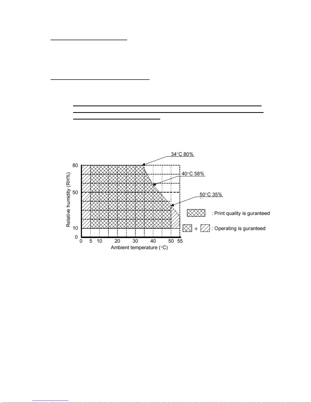
1.6- ENVIRONMENTAL CONDITIONS
1) Operating Temperature: 0 to 50ºC (32 to 131ºF)
If the printer is installed in outdoor applications in which the ambient
temperature is low, we suggest to use a blower fan heater to raise the
operating temperature over 0ºC.
2) Operating humidity: 10 to 80% (34ºC (93.2ºF) at 80%, non-condensing)
Fig. 1.1- Operating Temperature and Humidity Range

FENIX IMVICO TK23 OPERATION MANUAL
12/81
2 – INSTALLATION
2.1- FIXING THE TK23 PRINTER
The TK23 is an industrial printer designed to be fixed in a bigger case or structure, or
another kind of appropiate chassis. There are two models for the TK23 printer with 4
different fixing points each.
2.1.1 - TK23 INSTALLATION
• Fix the TK23 to the chassis by screwing, putting 4 metric screws (M4 / L10 mm)
through the holes marked with A and B in fig 2.1 - Fixing the TK23.
• Place all the screws in the same direction, from up to down.
• It is strongly recommended that the fixing holes of your chassis have an oval shape
so as the TK23 can move backward and forward for an easy manipulation.
• The paper-near-end sensor included in TK23 detects when remaining paper is about
17m long (65µm paper thickness).
A B
Fig. 2.1 - Fixing the TK23.
FENIX IMVICO TK23 OPERATION MANUAL
13/81
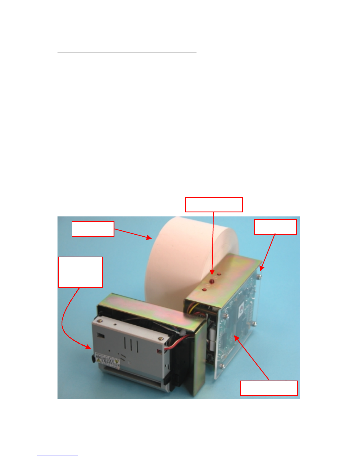
2.2- TK23 INSTALLATION CONSIDERATIONS
There are some general considerations to take into account when installing the printer
with the TK23 printer.
A wrong installation can cause many serious problems like paper jam, difficult
maintenance of the printer, difficulty in changing the paper roll, etc.
Moreover, a correct installation can prevent the printer from being damaged by external
agents, such as weather or vandalism.
The basic points that a correct installation must follow are:
• Smooth exit of the ticket. Prevent problems with static electricity due to the nature of
the used materials.
• Allow enough space and accessibility to reach the maintenance procedure points in
case it is needed. These points are:
• Thermal mechanism & Autocutter.
• Paper roll.
• Interface.
• Connectors.
• Led and Push-buttons.
Fig 2.2 - TK23 elements
Paper Roll
Thermal
mechanism
& autocutter
connectors
IF2200 interface
Led and buttons
FENIX IMVICO TK23 OPERATION MANUAL
14/81
For these reasons, FENIX suggests the following systems as solutions to a correct
installation:
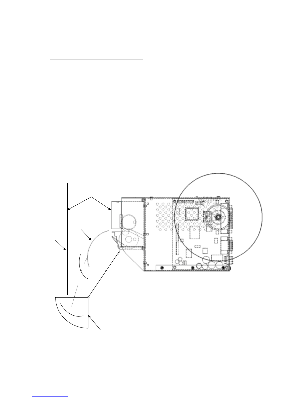
2.2.1- EXTERNAL CHUTE SYSTEM
The idea of this system is to internally print and cut the ticket inside the machine, and
then make it fall into a receptacle where the user can have external access. Therefore,
there must exist some distance between the printer and the front side of the user’s
chassis in order to build a useful chute for the ticket, and to be able to open the printer
thermal head.
Two points must be assured to make this system work right:
• The construction of the receptacle must avoid the user to reach any internal
parts of the machine.
• The way of the ticket from the printer outlet to the receptacle must be smooth,
clean and free of obstacles to allow the ticket to actually fall into it and avoid
paper jams or tickets that do not fall. Depending on the construction materials,
care must be taken with static electricity; otherwise tickets may get stuck
inside the machine and never reach the receptacle.
Next figure shows a scheme of this system:
Fig. 2.3 -External chute system.
Frontal side of
user’s chassis
Ticket
receptacle
Ticket
Make sure this distance allows the
opening of the printer thermal
head (min: 20mm)
FENIX IMVICO TK23 OPERATION MANUAL
15/81
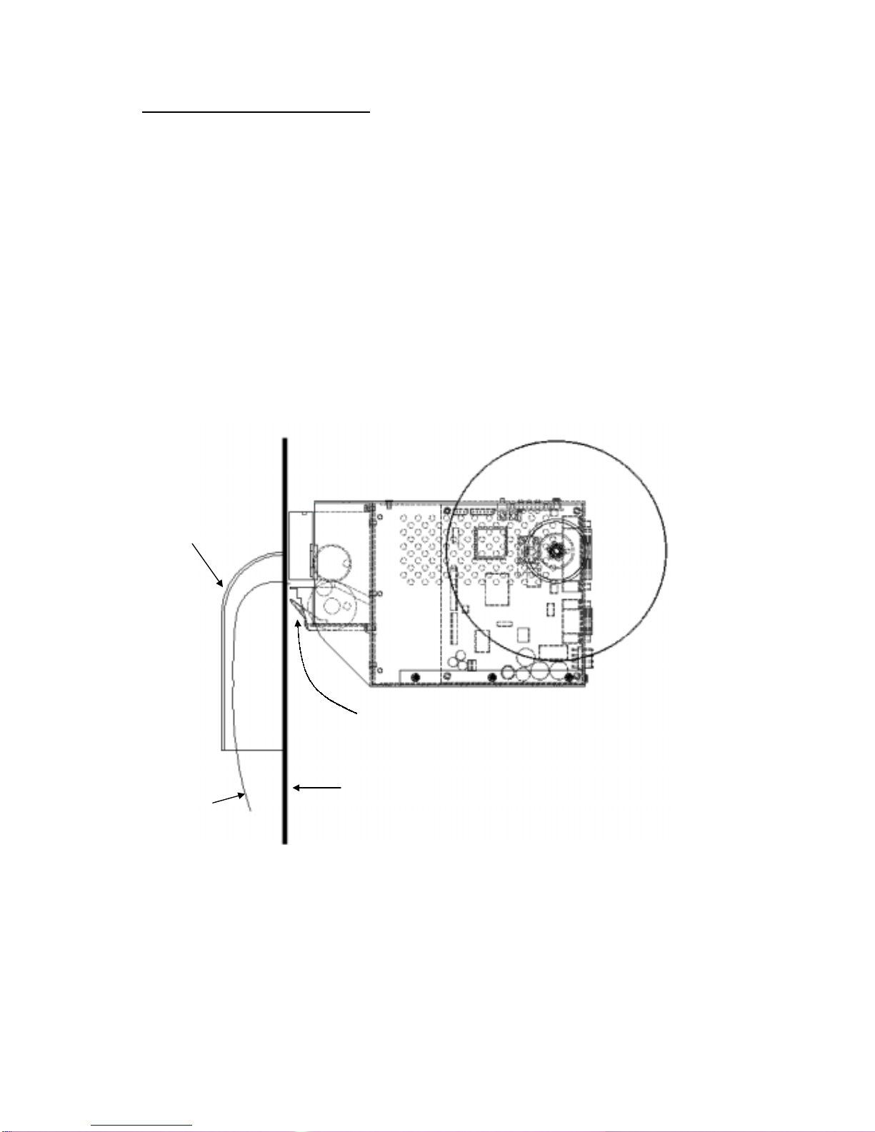
2.2.2- PAPER GUIDE SYSTEM
When using this system, the printer must be set quite near the front side of the user’s
chassis. The paper guide is to avoid external handling of the printer outlet.
Two points must be assured to make this system work right:
• Special care in the design of the part which goes from the printer outlet to the
paper guide (Paper jams can a occur due to an inappropriate design).
Depending on the construction materials, care must be taken with static
electricity; otherwise tickets may get stuck in the paper guide and never reach
the receptacle.
• As the printer is placed very near the user’s chassis, some system must be
implemented in order to move the printer when accessing the printing head
(i.e. giving the fixing holes of the chassis an oval shape to allow the printer
moving forward and backward). Otherwise there will be no access to the
printing head.
Next figure shows an scheme of this system:
Fig. 2.4- Paper guide system.
The distance between the mechanism and the frontal side of the user’s chassis may not
allow the opening of the printer thermal head. Take special care about this point when
designing your system.
Ticket
Paper guide
Frontal side of
user´s chassis
Head-up
lever

FENIX IMVICO TK23 OPERATION MANUAL
16/81
2.3- TK23 USER INTERFACE ELEMENTS
In the TK23, user can find the next connectors:
• CN1: Power supply connector.
• CN6: Serial RS-232 communications connector and
Parallel CENTRONICS communications connector.
Also, there are other interface elements that allows easy configuration of printer:
• Paper near-end sensor
• Paper Feed tact switch button
• Programming tact switch button
• Led indicator of Power ON
Fig. 2.5- TK23 connectors & elements location.
Power Supply
serial RS232 and
CENTRONICS
communications
Programming button Paper Feed button
Paper near-end sensor
Power ON indicator
FENIX IMVICO TK23 OPERATION MANUAL
17/81
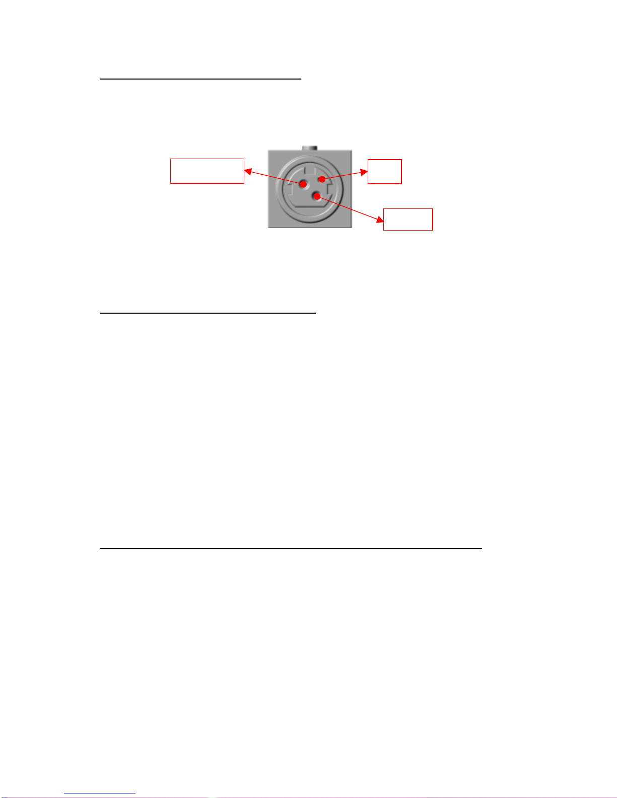
GND
24V DC nc
2.3.1- POWER SUPPLY CONNECTOR
Attach power supply cable to the 3-pin micro connector. Verify power supply voltage
before making the connection.
The connector is a female 3-pin HOSIDEN type, which have the following pin-out:
Fig.2.6- Power supply connector as seen from outside the TK23.
Use a 3-pin DC jack KPP-3P model or equivalent.
2.3.1.1 - Optional Power supply connector :
A special version of TK23 (under agreement only), can use for power supply a Male 4-
pin 0.156" pitch (3,96mm) disconectable Crimp style connector.
User side connector type: Housing: VHR-4N (JST or compatible)
Contact: SVH-21T-P1.1 (JST or compatible)
NOTE: All 4 pins must be connected. Terminals 2 and 3 are VCC (24V DC)
Terminals 1 and 4 are GND
The TK23 requires one power source: VCC (24V DC) for driving the thermal head and
motor. This voltage is internally regulated to 5V to control the electronic active parts.
The power supply must meet the following conditions:
VCC: 24V DC +/- 2,4V
Example of printhead current consumption (for the 80mm-wide mechanism):
Print head current consumption at a printing ratio of 35%:
(Printing ratio is defined as the number of dots/dot lines (576 dots)).
1) Peak current: 3.05 A (when all 208 dots are powered).
NOTE: Peak current is measured at the minimum resistive value of thermal
head and the maximum operating voltage.
Conditions: VH max: Head connector terminal voltage max. 26.4V
Rmin: Head resistance value min. 1800 Ohm.
The following formula is used to obtain the head drive peak current:
Ipeak = Vmax (volts) x 576 dots x printing ratio / minimum head resistance value (ohms)

FENIX IMVICO TK23 OPERATION MANUAL
18/81
2) Mean current: Approx. 1.4 A
Conditions: - Head terminal voltage = 24V
- Head resistive value Rh = 1800Ohm
- Mean energizing pulse width of 832 µs, synchronizing with 1667µs
motor cycle.
The following formula is used to obtain the head drive current:
Imean = [V(volts)/Rh(Ohms)] x 576dots x printing ratio x [energizing pulse width/cycle]
NOTES:
(1) If the number of dots that are energized at the same time is increased, a higher
current will flow; therefore, the user should use a power supply with a current
capacity adequate for the corresponding print duty.
(2) When designing lines and bit images, take the printing ratio and print duty into
consideration.
(3) Print quality may be poor if the printing ratio or print duty is high.
(4) Definitions:
• Printing ratio: the number of printing dots (energizing pulses)/dot line.
• Print duty: the number of printing dots (energizing pulses)/ elements/ paper
feed amount (two steps, including non-printing area)
WARNING: Beware not to invert the polarity of power supply. This may
irremediably damage the printer.
IMPORTANT NOTE ABOUT TK23 POWER SUPPLY:
The necessary supply of power depends on the content to print on the
ticket. A 150W power supply covers all adverse possibility (printing ratio of 100%
black at any temperature). However, if the average print ratio is not over 25%, a
60W power supply can be used. Any way, power supply must meet the peaks
current that mechanism requires, which are determined by the following formula:
Ipeak = [24 / 1800] x number of printing dots

FENIX IMVICO TK23 OPERATION MANUAL
19/81
2.3.2- SERIAL RS-232 CONNECTOR
2.3.2.1- Specifications
• Data transmission: Serial
• Synchronization: Asynchronous
• Handshaking: CTS/RTS control
• Signal levels (RS232): Logic “1” = -3 to –15 V
Logic “0” = +3 to +15 V
• Baud rate: 4800, 9600, 19200, 38400 bps (bps: bits per second)
• Data word length: 8 bits (fixed)
• Parity Settings: None, even, odd
• Stop bits: Fixed to 1.
• Connector (printer side): Male PHD 24 pin connector JST ref. S24B-PHDSS
Recommended female crimp conector: JST ref. PHDR-24VS
NOTES:
(1) The baud rate, and parity settings can be changed
(refer to point 3.4.2- PROGRAMMING MODE).
(2) The stop bit for the printer side is fixed to 1.
(3) The data word length is fixed to 8 bits.
Pin Signal
name Signal direction
(from the printer
side) Function
21 RXD Input Receive data
20 TXD Output Transmit data
22 /RTS Output Logic “0” indicates that the printer is connected and ready to
receive data, and logic “1” indicates that the printer is offline
or is BUSY.
The printer goes OFFLINE:
1) When the power is turned on until the printer becomes
ready for data transmission after it is initialised by a reset.
2) When the platen is open.
3) When the printer stops printing due to a paper-end.
4) When an error has occurred
The printer is BUSY when reception buffer is full (*)
23,24 GND - Ground
(*) reception buffer is full when it increases till the maximum capacity (32 Kbytes).
Table 2.1- Serial port pin-out.
Fig. 2.7- Serial interface connector as seen from outside the TK23.
Pin 24
Pin 23
Pin 2
Pin 1

FENIX IMVICO TK23 OPERATION MANUAL
20/81
2.3.2.2- Serial interface connection example
The cable, which has the signal connection, as shown below must be used.
PRINTER SIDE USER SIDE (PC)
CN6
Pin Num.
Signal
Name
Signal
Name
D-SUB9
Pin Num.
DCD 1
21 RxD RxD 2
20 TxD TxD 3
/DTR 4
23,24 SG SG 5
/DSR 6
22 /RTS /RTS 7
/CTS 8
RI 9
Table 2.2- Serial interface connection example.
NOTE: Transmit data to the printer after turning on the power and initializing the
printer.
The TK23 receives data continuously, even while performing printing operation.
The TK23 serial input/output signals (RXD, /RTS and TXD) can be RS232C level or TTL
level (see APPENDIX F- HOW TO ORDER).
The TK23 receives and checks serial data according to the transmission baud rate
programmed.
If the input data is not printed correctly, the transmission conditions between the host
device and the TK23 do not probably match. If this happens, the character “?” is
continuously printed and user must adjust the transmission conditions so that they
match.
Serial data output (TXD): output pin, SUB-D9-3
• Data is output according to the programmed transmission conditions.
Serial data input (RXD): input pin, SUB-D9-2
• Data input port
• Data is input from the host device according to the programmed transmission
conditions.
Serial busy (/RTS): output pin, SUB-D9-7
• Indicates whether or not the printer is ready to receive data.
• When the /RTS signal is “LOW”, data can be input.
.
NOTE:
For more information on serial data reception see point 3.5.9- SERIAL PORT
ERROR DETECTION FLOW CHART.
Connect the communications cable before turning the TK23 ON.
Table of contents
Other Fenix Imvico Printer manuals

Fenix Imvico
Fenix Imvico EPC1200 Series User manual

Fenix Imvico
Fenix Imvico TK14 User manual

Fenix Imvico
Fenix Imvico TK41 User manual

Fenix Imvico
Fenix Imvico TK51 Series User manual

Fenix Imvico
Fenix Imvico EPC1100 User manual

Fenix Imvico
Fenix Imvico SM3000 User manual

Fenix Imvico
Fenix Imvico TS1700 User manual

Fenix Imvico
Fenix Imvico KS55 Series User manual


