Fenix Imvico TS1700 User manual

TS1700 & TK18
THERMAL PRINTER S
Operation manual
Rev 2.1

TS1700/TK18 PRINTERS OPERATION MANUAL
INDEX
1 – INTRODUCTION.......................................................................................................3
2 – IMPORTANT NOTES ON T ERMAL PRINTER ANDLING...................................4
2.1. SAFETY PRECAUTIONS....................................................................................4
2.2. ABSOLUTE MAXIMUM RATINGS......................................................................5
2.3. CLEANING PROCEDURE AND PRECAUTIONS..............................................5
2.4. RECOMMENDATIONS.......................................................................................5
3 – GENERAL SPECIFICATIONS...................................................................................6
3.1. PRINTING SPECIFICATIONS.............................................................................6
3.2. C ARACTER SPECIFICATIONS.......................................................................6
3.3. PAPER SPECIFICATIONS..................................................................................6
3.4. COMMUNICATIONS INTERFACE......................................................................7
3.5. DIGITAL OUTPUT...............................................................................................7
3.6. INTERNAL BUFFER............................................................................................7
3.7. ELECTRICAL SPECIFICATIONS........................................................................7
3.9. MEC ANICAL SPECIFICATIONS......................................................................8
3.10. RELIABILITY AND ENVIRONMENTAL CONDITIONS.....................................8
4 – INSTALLATION..........................................................................................................9
4.1. TS1700/TK18 INSTALLATION CONSIDERATIONS...........................................9
4.2. MOUNTING T E PRINTER..............................................................................10
4.3. POWER SUPPLY..............................................................................................13
4.4. RS-232 SERIAL INTERFACE...........................................................................14
4.5. USB INTERFACE..............................................................................................15
4.6. P OTO-SENSORS...........................................................................................15
4.7. DIGITAL OUTPUT.............................................................................................17
5 – BASIC OPERATIONS.............................................................................................18
5.1. PAPER LOADING.............................................................................................18
5.2. OPEN CUTTER UNIT.......................................................................................19
5.3. BUTTON FUNCTIONS......................................................................................20
5.4. PAPER SENSOR..............................................................................................20
5.5. OPEN-PLATEN SENSOR.................................................................................20
5.6. OPTIONAL SENSORS......................................................................................20
5.7. LED INDICATOR...............................................................................................22
5.8. SPECIAL PRINTING MODES...........................................................................22
5.9. ERROR PROCESSING.....................................................................................23
6 – CONTROL COMMANDS.........................................................................................27
APPENDIX A – MEC ANICAL DIMENSIONS..............................................................55
APPENDIX B – OW TO ORDER- ACCESSORIES......................................................57
APPENDIX C – INTERNAL C ARACTER TABLES. LOADING EXTERNAL
C ARACTER TABLES........................................................................59
2/62

TS1700/TK18 PRINTERS OPERATION MANUAL
1 – INTRODUCTION
The TS1700/TK18 is a high performance thermal kiosk printer series. Its compact and functional
design covers many industrial uses (as in park lots, toll stations, laboratories etc.) It is capable of
printing text, graphics, logo and bar codes.
The main features of the TS1700/TK18 Series are:
•Simple installation and easy maintenance.
•Low noise thermal printing.
•Paper width: 58 mm.
•Up to 45 mm paper roll diameter.
•igh reliability: 100 million pulses or more. Abrasion resistance: 50 Km (NOTE 1).
•Power supply 12-24VDC.
•No-paper sensor.
•Paper-near-end sensor option.
•Ticket pick-up sensor option.
•Black mark sensor option.
•Optional output.
•igh speed printing up to 62,5mm/s. (NOTE 2).
•Printing resolution: 8 dots/mm (203 dpi).
•Automatic cut with partial or full cut capability.
•Port interface: - serial RS232C data input interface on-board (up to 115200 bps).
- Universal Serial Bus (USB).
•Two internal character fonts (A font = 12x24 dots. B font = 8x16 dots).
•Scalable font (independent scale in X/Y-axis), up to 64 times.
•Programmable character and line space.
•Bold, underline, reverse and rotate character capabilities
•Graphic bitmap printing capabilities.
•Several format bar code (EAN13, Code39, Code128 and ITF)
•Several 2D format Bar Code (QR and AZTEC)
•Control code based on ESC/POS commands (NOTE 3).
•exadecimal mode for easy software debugging.
•Self test mode feature.
•Automatic paper load.
•Three maintenance counters (On/Off times, alf hours, Meters)
•Input buffer of 32KBytes.
•Programmable digital output.
•Extended operating temperature range (-30ºC to +70ºC).
•Storage temperature range (-35ºC to +75ºC).
•Multiple logo load capability through Windows driver or command.
•Upgrading of firmware version through communication port (NOTE 4).
•TrueType font loading capability (NOTE 4).
•Windows 2000 and XP drivers and demo/configuration program.
•Linux Driver.
(1) Excluded when the same dots are printed continuously and/or damage is caused by dust and foreign materials.
(2) Print speed changes according to the baud rate in R 232 connection and temperature. Higher printer speed rates are
achieved at higher baud rates and U B connection.
(3) E C/PO are registered trademarks of eiko Epson Corporation.
(4) In order to upload new firmware or new TrueType font, FWLoader and FontLoader application programs are available
on demand.
This manual is the printer operations’ guide and is intended for the designer’s application. The
following sections contain a detailed description of both hardware and configuration software that allow
obtaining the maximum benefit of the printer capabilities.
3/62

TS1700/TK18 PRINTERS OPERATION MANUAL
2 – IMPORTANT NOTES ON THERMAL PRINTER
HANDLING
In order to preserve the life of the printer, it is necessary to keep in mind some precautions on the
handling of the TS1700 printer. Please read carefully the following points in order to make a good use of
the printer.
2.1. SA FETY PRECAUTIONS
•Before using the printer, read carefully section - IN TALLATION.
•NEVER connect the external power supply with the wrong polarity. This could permanently
damage the printer.
•Turn off the printer immediately if it produces smoke, a strange smell or an unusual noise. Keeping
on using the printer could cause fire. Unplug the equipment immediately and contact your official
distributor.
•NEVER connect cables with different connectors from the ones mentioned in this manual. Failing
on doing so could permanently damage the printer.
•Use a power supply whose output voltage is within the specification range stated in this manual.
Over voltage can permanently damage the printer. Under voltage can cause malfunctions.
•NEVER wet TS1700 thermal printer with water or any other liquid. If any liquid is spilled inside the
equipment, unplug the power cable immediately and contact the technical service.
•Make sure the printer is on a steady, securely fixed surface. If the printer falls down, it could break
or damage.
•NEVER use the printer in high humidity or in locations with high risk of fire.
•NEVER place heavy objects on top of the printer and never lean on it.
•NEVER put any object inside of the printer, as it could cause hardware damage on it, such as
short-circuit, print head breaking or general failure of the printer.
•NEVER shake the printer.
•NEVER disassemble or modify the hardware of the printer.
•NEVER try to repair the printer. Please contact your official distributor in case of failure.
•As the printer contains electromagnets (inside of the motor), it should not be used in excessively
dirty environments or places with dust or metal particles.
•NEVER print without paper loaded or without the cover closed, as the thermal print head life can
be highly shortened.
•NEVER pull the paper out when the cover is closed. Use the paper advance button instead.
•Avoid touching accessible parts with metallic objects, such as screwdrivers or tweezers, the print
head thermal elements as well as the electronic printed circuit. They are delicate parts.
•NEVER touch with bare hands the areas around the print head and the motor surface as they
become very hot during and just after printing; wait 15 seconds after printing to let them cool down.
•NEVER touch the surfaces of the print head thermal elements or the electronic printed circuit, as
dust and dirt can stick to their surface and cause damage by electrostatic discharge. Moreover,
some electronic components can get very hot during operation.
•The thermal paper contains Na+, K+ and Cl- ions that can cause harm to the print head elements.
Therefore, use only the specified paper.
•If the printer has not been used for long period of time and the paper was loaded, the paper could
become deformed by the drive roller pressure. It is recommended to make it advance at least 30
mm before printing again.
•For safety reasons, unplug the printer if it is not going to be used over a long period of time.
•Do not rint continuously (without sto ing) for more than 6 minutes.
4/62
TS1700/TK18 PRINTERS OPERATION MANUAL
2.2. ABSOLUTE MAXIMUM RATINGS
Supply voltage . . . . . . . . . . . . . . . . . . . . . . . . . . . . . . . . . . . . . . . . . . . . . . . . . . . . . . . . . . . +30 VDC
Operating temperature range . . . . . . . . . . . . . . . . . . . . . . . . . . . . . . . . . . . . . . . . . . . −30°C to 70°C
Storage temperature range . . . . . . . . . . . . . . . . . . . . . . . . . . . . . . . . . . . . . . . . . . . . . −35°C to 75°C
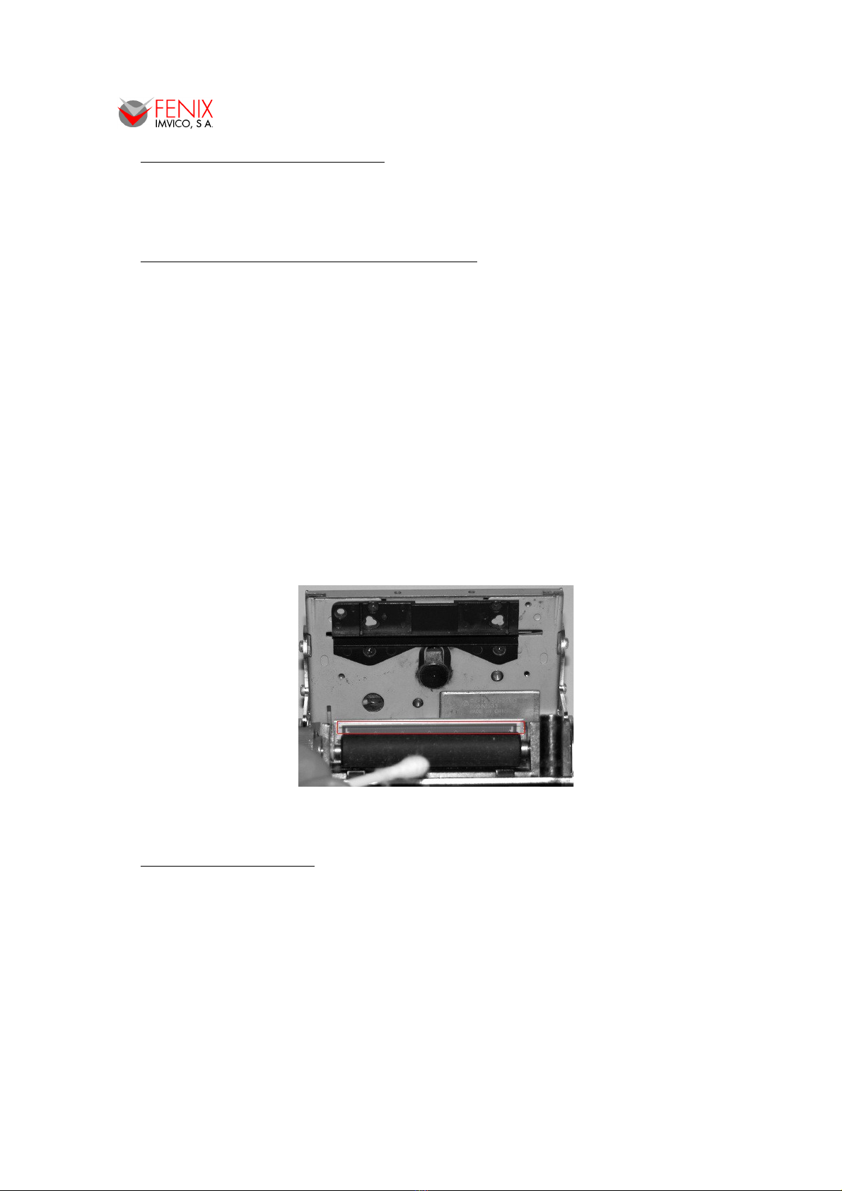
2.3. CLEANING PROCEDURE AND PRECAUTIONS
In order to clean the thermal print head, proceed as indicated by the following steps:
1- Unplug the power supply cable and open the cutter unit. See section – OPEN THE
CUTTER UNIT.
2- Pull the paper lever in order to release the platen.
3- Soak a cotton sponge in alcohol (ethanol, methanol or IPA), and rub it gently along the
thermal head in order to remove the possible accumulation of paper particles.
4- Wait for alcohol to evaporate before inserting the paper roll and closing the cover.
FENIX recommends cleaning the thermal print head periodically (every 2 or 3 months) in order
to keep an optimal print quality.
NOTES:
The print head may be hot after printing. Make sure it has thoroughly cooled down
before proceeding to clean it.
Never touch the thermal elements of the print head with your hands.
Never use metallic or piercing elements to clean the print head, as they could scratch it.
Fig.2.1. Thermal print head cleaning.
2.4. RECOMMENDATIONS
•The plug has to be located near the printer and has to be easily obtainable.
•Before connecting any communication data cable, check the printer is working properly by
executing the self-test.
•Set the TS1700 in a place where the connection cables do not suffer stretching or cross with
each other.
•IMPORTANT!!! Since the printer demands high current peaks during operation it is advisable to
make the power supply cables the shortest possible.
5/62

TS1700/TK18 PRINTERS OPERATION MANUAL
3 – GENERAL SPECIFICATIONS
3.1. PRINTING SPECIFICATIONS
Printing method Thermal line printing
Dot density 203 x 203 dpi (1)
Printing direction Unidirectional with friction feed
Printing width 48 mm (384 dots)
Printing speed igh speed mode: up to 62,5mm/s (2)
P per feed speed 62,5mm/s (continuous paper feed)
(1) ‘dpi’: dots per inch. 1 inch = 25.4mm; 203 dpi = 8 dots per mm
(2) Printing speed could vary depending on the print head temperature as well as the command processing and
the data transmission speed. Low transmission speed could cause intermittent printing. It is recommended to
transmit data to the printer as quickly as possible.
3.2. CHARACTER SPECIFICATIONS
Ch r cter per line (def ult) Font A: 24
Font B: 32
Ch r cter sp cing (def ult) 0.5 mm (4 dots)
Ch r cter structure Font A: 12 x 24 dots (1.5 x 3 mm). (default)
Font B: 8 x 16 dots (1 x 2 mm).
Ch r cter size (mm) (1)
Font A Wx (mm) – cpl(2) Font B Wx (mm) – cpl
Standard
Double-width
Double-height
Double width/height:
1.5 x 3 – 24
3 x 3 – 12
1.5 x 6 – 24
3 x 6 – 12
1 x 2 – 32
2 x 2 – 16
1 x 4 – 32
2 x 4 – 16
Number of ch r cters Alphanumeric characters: 95
Extended Graphics: 128 per page
Line sp cing (def ult) 1,875mm (15 dots)
(1) Characters can be scaled up to 64 times bigger than their normal size.
(2) ‘cpl’: characters per line.
3.3. PAPER SPECIFICATIONS
P per type Thermal
P per specific tions
At –5ºC to 50ºC TF50KS-E2D (59µm paper )
TF77KS-E2 (95µm paper)
TL69KS- G76 (label paper)
TL51KS-R2 and TL69KS-R2 (high heat-resistant paper)
At 5ºC to 40ºC TW80KK-S (2-ply thermal paper)
From Nippon Paper Industries
P per roll size
Width: 58 +0/-1mm
Minimum inside diameter : 25 mm
Maximum outside diameter: 45 mm → TS1700
80 mm → TK18
6/62
TS1700/TK18 PRINTERS OPERATION MANUAL
3.4. COMMUNICATIONS INTERFACE
Seri l Serial interface RS232 (baud options 115200, 38400, 19200, 9600)
USB USB 2.0 480Mbit/s
3.5. DIGITAL OUTPUT
M x Drive current 100mA continuous, 200mA peak.
M x supported volt ge 45V DC
3.6. INTERNAL BUFFER
The standard TS1700 printer has a 32 Kbytes internal memory buffer, whose functionality is
dynamically shared by the receiving buffer.
The buffer is being filled at the same time that buffered data is being printed, for that reason high
transmission speed is required in order to ensure that data is available for printing at any time. Data
transfer of at least 115200 baud or USB connection increase the printing performance substantially.
3.7. ELECTRICAL SPECIFICATIONS
Power supply: 12V to 24V DC ± 10%
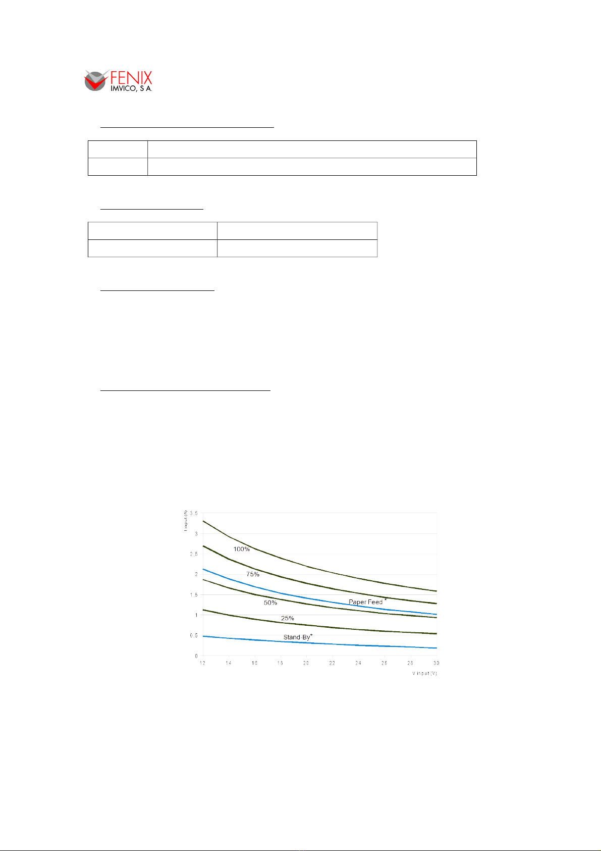
Consumption: The figures below show the relationship between average current and power
consumption with the input voltage at an ambient temperature of 25ºC. Each graph contains 6
parameters corresponding to when printer is in Stand-by, when the printer is just feeding paper,
and when the 25%, 50%, 75% and 100% the dots are energized and paper is being feed at the
same time. In both graphs, parameters in blue have been multiplied by 10 for better
representation.
*Paper Feed and Stand-by parameters are shown multiplied by 10.
Fig.3.1. Current consumption vs input voltage.
7/62

TS1700/TK18 PRINTERS OPERATION MANUAL
*Paper Feed and Stand-by parameters are shown multiplied by 10.
Fig.3.2. Power consumption vs input voltage.
3.8. MECHANICAL SPECIFICATIONS
Over ll dimensions (W x D x H)
(mm)
100.1 x 38.2 x 72.6 → TS1700
100.1 x 145.51 x 74.85 → TK18
Weight (without p per) 310g → TS1700
580g → TK18
3.9. RELIABILITY AND ENVIRONMENTAL CONDITIONS
Oper ting temper ture -30 to 70ºC
Stor ge temper ture -35 to 75ºC (without paper, in a dry place)
Life sp n ( t 25ºC )
Activ tion pulse resist nce 100 millions pulses or more (print ratio=12’5%).
Abr sion resist nce 50 Km or more
Autocutter service life
Paper: 0,1 mm
(20ºC – 45ºC, 10% -65% R )
500.000 cuts
8/62

TS1700/TK18 PRINTERS OPERATION MANUAL
4 – INSTALLATION
4.1. TS1700/TK18 INSTALLATION CONSIDERATIONS
There are some general considerations to take into account when installing the TS1700/TK18
printer.
A wrong installation may cause many issues like paper jam, difficult maintenance of the printer,
difficulty in changing the paper roll, etc. Moreover, a correct installation can prevent the printer from
being damaged by external agents, such as weather or vandalism.
This printer is designed to be installed vertically or horizontally in a case, closet, or another kind of
appropriate chassis.
The basic points that a correct installation must follow are:
•Allow enough room and accessibility to reach the maintenance procedure points in case it is
needed. Take notice all user accessible parts in the printer.
•Smooth exit of the ticket. Prevent problems with static electricity due to the nature of the
used materials. Be sure to make a good earth connection.
•Since the printer is placed very close the user’s chassis, some system must be implemented
in order to move the printer when accessing the printing head (i.e. giving the fixing holes of
the chassis an oval shape to allow the printer moving forward and backward).
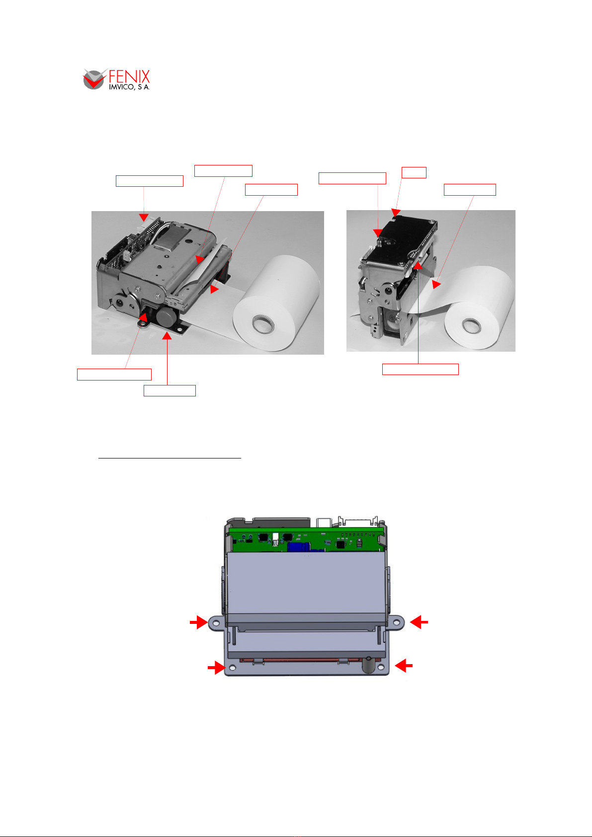
Fig. 4.1. TS1700 open.
9/62
TS1700/TK18 PRINTERS OPERATION MANUAL
TS1700 printer comes in two different versions: right angle or straight (See APPENDIX – HOW
TO ORDER - ACCE ORIE ). Both have the same paper output but the paper input is different as it is
shown in the figures below.
Fig.4.2. TS1700 paper inputs and accessibility.
4.2. MOUNTING THE PRINTER
The TS1700 printer has 2 tabs and 2 holes so that the user can fix it on a chassis with screws or
rivets. In most cases, given that the TS1700 printer is very light, fixing through the tabs may be enough,
like in TK18 assembly.
Fig.4.3. TS1700 Fixing holes.
10/62
Paper roller lever
Paper knob
Paper input Paper input
Paper feed button
Rigth angle Straight
USB connector
Main connector
Paper output LED

TS1700/TK18 PRINTERS OPERATION MANUAL
The TK18 printer is basically a paper support adapted to the TS1700 printer, which can facilitate
the integration of the printer in another system. Accepts rolls up to 80mm diameter and has a small
platform that helps automatic paper loading. The TK18 printer also includes in the assembly the paper
near-end sensor. In the TK18 rinter, only is ossible to install the TS1700 with straight a er
in ut.
Fig.4.4. TK18 = TS1700 + paper support.
The TK18 has 3 holes to fix and it can be mounted horizontally or vertically.
Fig.4.5. TK18 Fixing holes.
11/62

TS1700/TK18 PRINTERS OPERATION MANUAL
Depending on the position that printer takes in the final installation, the TS1700 is provided with a
"gripper" which ensures that the cutter will not open vibrations or some accidental blow.
Consider carefully this point when ordering (see APPENDIX -HOW TO ORDER).
•TS1700 HORIZONTAL MOUNTING (the paper comes up).
•TS1700 VERTICAL MOUNTIG (the paper exits horizontally).
•TS1700 UPSIDE DOWN MOUNTING (the paper goes down).
12/62
Standar type
Right angle.
Locking cutter system
by magnet.
TS1700/12-C
Locking cutter system
by gripper.
TS1700/12-X-BX
Locking cutter system
by gripper.
TS1700/12-X-BX
Fig.4.6. orizontal
mounting.
Fig.4.7. Vertical
mounting.
Fig.4.8. Upside down
mounting.
TS1700/TK18 PRINTERS OPERATION MANUAL
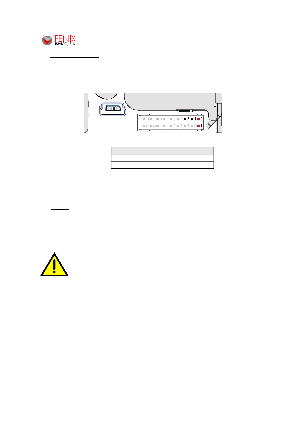
4.3. POWER SUPPLY
The TS1700 is powered by an external power supply by means of four pins of the shared
connector that is also used for RS232 communication, photo sensors and digital output. Although the
connector is polarized, if forced it could be connected inverted so it is very important to observe polarity
before plugging the connector in.
Fig.4.9. Power supply connector J1.
Pin number Description
1, 2 VIN (12V to 24V DC)
4, 6 GND
The power supply female connector must be a:
ousing: PHDR-18VS (JST Ref.)
Terminal: SPHD-001T-P0.5 or equivalent.
Wire: 22 AWG or thicker (GND & VIN)
NOTES:
(1) If the number of dots that are energized at the same time is increased, a higher current
will flow; therefore, a power supply with an adequate current capability must be used.
(2) When designing lines and bit images, take the printing ratio and print duty into
consideration. Print quality may be poor if the printing ratio (energizing pulses/dot line) or
print duty is high.
(3) Average energizing pulse width is defined as 64 of 192 dots/dot line that are energized.
WARNING: Beware not to invert the olarity of ower su ly. This may
irremediably damage the rinter. Ensure that the voltage is the correct
one. Use the 4 terminals (4 wires) with 0.35mm² minimum section each.
NOTE ABOUT POWER SUPPLY:
The current demand depends on the density of the printout. A 60W power supply covers all
adverse possibility (see section - ELECTRICAL PECIFICATION ).
FENIX offers different power supplies as an accessory option (See APPENDIX – HOW TO
ORDER).
13/62
TS1700/TK18 PRINTERS OPERATION MANUAL
4.4. RS-232 SERIAL INTERFACE
4.4.1- RS-232 Serial interface s ecifications
•Data transmission type: Serial
•Synchronization: Asynchronous
•Flow control: None, ardware and Xon/Xoff
•Signal levels (RS232): MARK = -3 to -15 V Logic ‘1’/OFF
SPACE = +3 to +15 V Logic ‘0’/ON
•Speed: 9600, 19200, 38400 and 115200 baud.
•Data length: 8 bits
•Parity: none, even and odd
•Stop bits: Fixed to 1
4.4.2- Change between online and offline mode
The printer is in offline mode:
1) When powering up or resetting the printer, until the printer is ready to receive data.
2) When the door is opened.
3) After pressing the button while the paper advances.
4) When ‘out of paper’ causes the printer to stop printing.
5) When the power supply has a temporal abnormal voltage change.
6) When an error has occurred.
4.4.3- Serial RS-232 interface ins assignment
The assignments of the terminals of the RS-232 connector and the functions of its signals are
described in the following figure and table:
Fig.4.10. Serial RS-232 interface pins.
Pin number Signal name Function
5 SGND Signal ground
7 RXD Data reception line
8 TXD Data transmission line
9 RTS Indicates whether the printer is busy
14/62

TS1700/TK18 PRINTERS OPERATION MANUAL
4.5. USB INTERFACE
The TS1700/TK18 USB interface has the following general features:
•USB specification USB 2.0 (480Mbits/s full speed)
•Transfer type Bulk
•Maximum receive/transmit endpoint size 64 bytes
•Current consumption from USB bus 2mA max.
4.5.1- Assignments of USB connector terminals
Pin Signal name
1 VBUS
2 D –
3 D+
4 GND
5 NC
Fig.4.11. TS1700/TK18 USB connector.
USB Mini-B series connector has to be used.
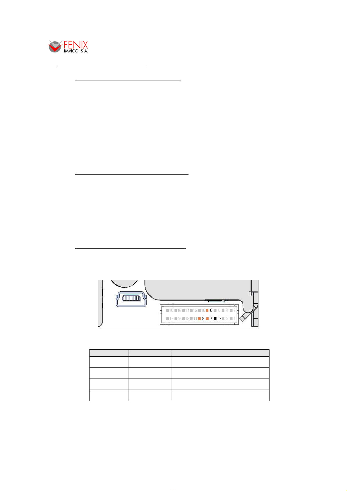
4.6. PHOTO-SENSORS
The TS1700 optionally allows control up to 3 auxiliary sensors, for which a specific functionality
has been assigned. The sensors are not included in the TS1700 rinter, but can be urchased as
an accessory ( See APPENDIX – HOW TO ORDER - ACCESSORIES ) :
Fig.4.12. Photo-sensors interface pins.
Pin
number Function
10 Driver Near-end-paper diode polarization pin
11 INPUT Near-end-paper signal
12 Driver Ticket picked-up diode polarization pin
13 INTPUT Ticket picked-up signal
14 Driver Black-mark diode polarization pin
15 INTPUT Black-mark signal
16, 17, 18 - Signal ground
15/62
Pin #5
Pin #1

TS1700/TK18 PRINTERS OPERATION MANUAL
The sensors are photo-transistor type, and are mounted on a small PCB to facilitate installation.
Connect
to pin
number
Printer TS1700
Near-end
paper
sensor
Black
Mark
sensor
“Ticket
Pick Up”
sensor
Driver_In 10 14 12
GND 16 17 18
Signal_Out 11 15 13
Fig.4.13. Photo-sensor pin out (Ref. Fotocélula FCX2).
1- Near-end- a er sensor. The function of this sensor is to warn the maintenance operator
that the printer is running out of paper although there is still paper to print few tickets. This
sensor must be enabled when installed on the printer.
An example of installing this sensor can be fix it near the paper axis, as shown in the
following picture concerning the TK18 printer.
Fig.4.14. Paper near-end sensor installation example (TK18).
2- Ticket icked u sensor. The target of this sensor is to inform to system (printer host) if the
ticket printed has been or not picked up by the user. For example, it will blink an error
pattern when a ticket has been printed but the user has not picked it up and it could cause a
paper jam if another ticket is printed
3- Black mark sensor. It is used when printing tickets onto a pre-cut paper roll which have a
black mark on each ticket. This sensor will help the printer to locate the edges of the ticket
and print accordingly. The black mark can also be a hole. This sensor must be enabled
when installed on the printer.
For the latter 2 cases, FENIX offers an optional bracket that allows several options for
mounting the photo-sensors FCX2.
•According to the positioning of the sensor in the bracket, can be mounted under (1) or
above (2), allowing the sensor is more or less removed from the paper exit.
•According to the positioning of the bracket on the TS1700, optical mark detection or
ticket pick up becomes possible on both sides of the paper: the printed one (A) or the
back one (B).
•The sensor PCB can be attached by screw + nut or glued (double-sided adhesive,
heat-fusion silicone, etc.).
•The scope of the sensor is about 10mm.
16/62

TS1700/TK18 PRINTERS OPERATION MANUAL
Fig.4.15. Ticket picked up sensor and/or black mark sensor installation examples.
4.7. DIGITAL OUTPUT
The TS1700 has an optional digital output which can be used for different purposes such a blink
and external warning light when a ticket has not been picked up or the printer is running out of paper,
activate a beeper when previous or other events are triggered, etc.
Fig.4.16. Digital output pin-out.
The digital output can be triggered either by any of the error events or can be activated
instantaneously using the same command: DC3 p m ton toff .
The digital output provides a signal that can blink or stay stable for up to 16 cycles. In case that a
blinking output is preferred, the time the output stays on and off are also programmable.
17/62
1
2
A
B

TS1700/TK18 PRINTERS OPERATION MANUAL
Fig.4.17. Digital output examples.
The transistor's out ut ca ability is: Vco = 45V , IC = 100mA. Values beyond this absolute
maximum ratings could result in a ermanent damage of the device.
5 – BASIC OPERATIONS
5.1. PAPER LOADING
There are mainly two ways of loading paper: automatic and manual. In any case, before starting
the paper load sequence, please make sure the paper roll has been placed in the right way.
5.1.1- Automatic a er loading
1. Make sure the TS1700 is power supplied.
2. Remove any rest of paper if there is any
3. Make sure that the platen is closed.
4. Make sure the paper end is cut in a straight way.
5. Thread the paper roll with the right orientation as shown in the next figure. The thermal paper
has only one printing side (thermal side). If there are doubt about which one is the printing side,
just scratch the paper and the thermal side will show up the track on.
6. Once the printer has detected the paper, it will automatically start the paper load sequence
which consist of feeding few millimeters of paper at a very low speed. Note: running at low
speed, the motor will be noisier.
Fig.5.1. Automatic paper loading.
18/62
Thermal side

TS1700/TK18 PRINTERS OPERATION MANUAL
5.1.2- Manual a er loading
To perform the manual paper load operation thread the paper into the paper input. Then turn the
paper knob clock-wise to feed paper into the paper path.
It is possible also to load the paper by raising the cutter unit and the platen.
Fig.5.2. Manual paper loading.
5.2. OPEN CUTTER UNIT
Sometimes is could be required to rise the cutter unit for maintenance operations as cleaning the
printing head, removing a paper jam, etc.
(1) Simply lift the cutter up to keep fixing it up.
(2) If it is necessary to open the print head also, pull up the paper roller lever.
(3) Finally, if is there any rest of paper inside the printer mechanism it can be removed by pushing
it from the paper input nozzle with another paper or by turning the paper roller knob clock-wise.
Fig.5.3. Open cutter unit.
19/62
1
23

TS1700/TK18 PRINTERS OPERATION MANUAL
5.3. B UTTON FUNCTIONS
Fig.5.4. TS1700 button.
The on-board button has the following functions:
•PAPER FEEDING: when the printer is powered on pressing the button will feed the paper.
The paper roller will not move under the following conditions:
- The paper roll end sensor detects a paper end.
- When the door is open.
- When another non-recoverable error is present.
•ELF-TE T MODE: If pressed on start-up with the door closed, it activates this mode.
•HEXADECIMAL MODE: In order to activate it, if the button is still pressed when the full Self-
test has been printed, the printer will prompt the user to hold the button to enter this mode. If
we do not hold the button in the next 3 seconds, the printer will exit to normal operation.
5.4. PA PER SENSOR
The TS1700 has an integrated photo-sensor for ‘out of paper’ detection. The out of paper sensor
has the basic function of informing the printer controller about the existence of paper (on the printing
line). Because there are some actions (as an example, printing without paper) that could seriously
damage the mechanism, this error blocks all the printer activities. Final user can detect this errors by the
LED blinking pattern and the application developer can test them through the DEL EOT command,
being able to act accordingly. This error events can be also associated to the digital output in a way that
when it is triggered it is possible to switch an external device.
5.5. OPEN-PLATEN SENSOR
The TS1700 has an integrated photo-sensor to detect the opening of the platen. The operation in
case this error is detected is basically the same as the preceding error.
NOTE: If TS1700 detects no paper or platen open while is printing it will stop the communication in
order not loose any data.
5.6. OPTIONAL SENSORS
There is also option for three more sensors as described in section - PHOTO- EN OR . These
are ‘near-end paper’ sensor, 'ticket picked-up' sensor and 'black mark' sensor.
•Near-end-paper sensor detects when the paper roll is near its end of file. This error, by
default, does not stop printing, but through the E C c 4 command, it can be achieved that the
‘near-end paper’ detection stops the printing. Since no mechanical solution is provided for the
installation of this sensor depending how it is mounted it will detect a quantity of remaining
paper in the roll. Final user can detect these errors by the LED blinking pattern, and the
application developer can test them through the DEL EOT command, being able to act
accordingly. This event can be also associated to the digital output in a way that when it is
triggered it is possible to switch an external device.
20/62
This manual suits for next models
1
Table of contents
Other Fenix Imvico Printer manuals

Fenix Imvico
Fenix Imvico TK14 User manual

Fenix Imvico
Fenix Imvico SM3000 User manual

Fenix Imvico
Fenix Imvico EPC1200 Series User manual

Fenix Imvico
Fenix Imvico TK51 Series User manual

Fenix Imvico
Fenix Imvico TK41 User manual

Fenix Imvico
Fenix Imvico TK23 Series User manual

Fenix Imvico
Fenix Imvico EPC1100 User manual

Fenix Imvico
Fenix Imvico KS55 Series User manual


