Ferax 57
Ajuste de la escuadra antidesgarro
Fig. 4
• Coloque el soporte (12) en la cepilladora
• Apriete la perilla (11)
• Ajuste la escuadra sobre el soporte
• Establezca el ancho de corte correcto y apriete la tuerca mariposa
4.CONSERVACIÓNYMANTENIMIENTO
Extraiga siempre el enchufe de la toma de red antes de realizar trabajos de
conservación y mantenimiento.
Lacuchilladecepilladosedesgastadespuésdeunciertotiempodeutilización.Sisigue
utilizandounacuchilladespuntadaodeteriorada,veráVd.reducidalaeficaciadesutrabajo,y
eventualmentepodríasobrecargarelmotor. Compruebe regularmente la cuchilla para
detectarposiblesdesgastesodeterioros;segúnsuestado,seráconvenientesusustitución.
Desmontajedelacuchilladelcepillo
Fig.3
Utilicelallavedebocaanexa(accesorios).Primero,suelteconlallavedebocalostrestornillos
deapriete(6)yextraigalacuchilla(3),labasedelacuchilla(2)yelsoportedelacuchilla(4)del
husoportador(1).
Montajedelacuchilladelcepillo
Fig.3
Tomelanuevacuchilla (3) ycolóquelaentreelsoporte de la cuchilla(4)ylabase de lacuchilla(2).
Ahoraenrosquelostornillosde apriete (6)enelsoportede la cuchillatantocomoseaposible.No
tantocomoparaquela cuchilla ysubasevuelvana soltarse delsoportedelacuchilla.A
continuación,introduzcaconjuntamentelacuchilla, su soporteysubaseen el husoportador.
Cuchilla,soporteybaseson fijados ahoraconjuntamenteenelhuso portador desenroscando
conlallavedeboca los tornillosdeapriete,inmovilizándoseasí cuchilla, soporteybase.
¡Atención! Desenrosquelostornillosdeaprietetantocomoseaposibleparagarantizarasí
unafijaciónsuficiente.
¡Atención!
• Enlostrabajosdemontajeydesmontajedelacuchilla,asegúresedequetodaslaspiezas
(cuchilla,basedelacuchilla,soportedelacuchillayhusoportador)esténlimpias.Deben
eliminarsesuciedadesyeventualescapasdesuciedad.
• Lostornillosinbus(5)estánaseguradosconcola.Estostornillosnopuedenregularse.El
reglajedeestostornillossólopuedeserllevadoacaboporelfabricante.
Compruebe regularmente que los tornillos de apriete estén bien sujetos.
Apriételos siempre bien fuerte.
ES
08 Ferax
4.CARE& MAINTENANCE
Before undertaking any care or maintenance always remove the mains plug from
the socket.
Theplaningtoolbecomeswornafteraperiodofoperation.Ifyouuseabluntordamaged
planingtooloperationalefficiencyisreducedandtheelectricmotormightbecomeoverloaded.
Checktheplaningtoolregularlywithregardtowearordamage.Dependingonitscondition,the
planingtoolwillhavetobereplaced.
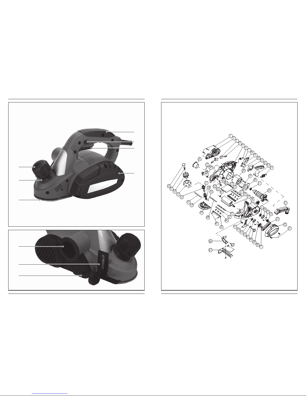
Removalofplaneblade
Fig.3
Usetheenclosedopen-jawedspanner(Accessories).Firstunscrewthethreeclamping
screws(6)withtheopen-jawedspannerandremovetheplaneblade(3),theplanebladeholder
(2)andtheplanebladesupport(4)fromtheholdingshaft(1).
Installationofplaneblade
Fig.3
Takethenewplaneblade(3)andpositionitbetweentheplanebladesupport(4)andtheplane
bladeholder(2).Nowturntheclampingscrews(6)asfaraspossibleintotheplaneblade
support.Butnotsofarthattheplanebladeandtheplanebladeholderbecomedetachedagain
fromtheplanebladesupport.Afterwards put the plane blade, plane blade holder and plane
bladesupporttogetherintotheholdingshaft.Theplanebladesupport,planebladeandplane
bladeholderwillnowbefastenedtogetherintheholdingshaftbyreleasingtheclamping
screwswiththeopen-jawedspannerandthustheplaneblade,planebladesupportandplane
bladeholderareclampedinposition.
Attention!Unscrewclampingscrews asfasaspossible sothatasufficientattachmentisensured.
Warning!
• Wheninstallingandremovingtheplaneblade,carehastobetakenthatallparts(plane
blade,planebladeholder, plane blade support and holding shaft) are clean. Dirt or possible
existinglayersofdirthavetoberemoved.
• TheAllen screws (5) are secured with an adhesive.Thesescrewsmustnotbeadjusted.The
positionofthesescrewsmayonlybealteredbythemanufacturer!
Check regularly if the clamping screws are tightened firmly. Always tighten screws
firmly.
Replacingthedrivebelt
Fig.5
• Loosenscrew(15)andtakeoffthebeltcover(16).
• Removeworndrivebelt(17).
• Beforeassemblinganewdrivebelt,cleanbothbeltpulleys.
GB