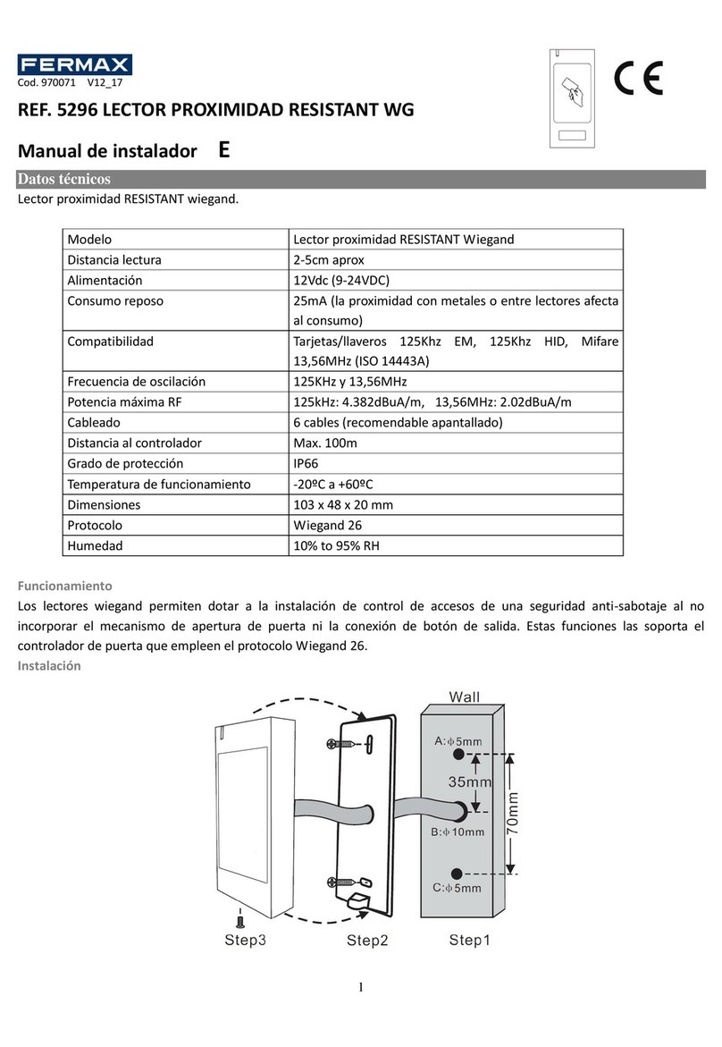
Fermax DESFIRE User manual

INSTALLATION MANUAL
INSTALLATION MANUAL
AUTONOMOUS PROXIMITY READER DESFIRE

Pag 2
Pag 2
Cod. 970206I V01_21
Cod. 970206I V01_21
CONGRATULATIONS ON YOUR PURCHASE OF THIS QUALITY
PRODUCT!
Fermax develops and manufactures systems of renown that meet
the highest standards of design and technology. We hope you enjoy
its range of functions.
CONGRATULATIONS ON YOUR PURCHASE OF THIS QUALITY
PRODUCT!
Fermax develops and manufactures systems of renown that meet
the highest standards of design and technology. We hope you enjoy
its range of functions.
Technical information booklet published by FERMAX ELECTRONICA.
As part of its policy for constant improvement, FERMAX ELECTRONICA
reserves the right to modify the content of this document and the characteristics
of the products referred to therein at any time and without prior notice.
Any modication will be reected in subsequent editions of this document.

Pag 3
Pag 3
Introduction...................................................................... 4
Wiring Diagrams.............................................................. 6
Connection Grid............................................................... 7
Technical Features /Default Values ................................. 7
Autonomous System Operating Modes........................... 8
- Activating the Card Reader ...................................... 8
• MASTER Card Reset ....................................... 8
-Activating Personal Cards......................................... 9
-Deactivating Personal Cards.....................................10
-Adjusting the Door Opening Time .............................11
-Adjusting the Time the Door is Open ........................12
-Copying .....................................................................13
- PC Management ......................................................15
INSTALLATION MANUAL
TABLE OF CONTENTS
INSTALLATION MANUAL
TABLE OF CONTENTS

Pag 4
Pag 4
INTRODUCTION
INTRODUCTION
The AUTONOMOUS proximity reader can control up to 400 cards.
Each of these cards, which operate without any type of maintenance, is
equipped with a unique electronic code (there are no two cards with the
same code).
FERMAX Desre readers include an encryption system to guarantee the
security of the installation (please consult with the Technical Service).
Reader encryption is done by the distributor and the following equipment
is necessary for you, as the installer, to encrypt the identiers (cards
and key fobs):
- PC with Desre Security Programmer software.
- Desktop programmer to encrypt readers, encrypt cards and read
card identiers.Part number F04534.
- Desktop reader to read the card identiers.Reference F04533.
Once activated, you can use them to open the relevant access door. To
this end, it is simply necessary to swipe (momentarily approximate) the
card to the proximity reader.
As it operates on a radio frequency, no physical contact is necessary,
meaning you can even swipe the card without taking it out of your wallet.
The maximum reading distance is 2 cm.
For more details on encryption, see manual 970210 Desre Software.
The proximity reader has various light indicators, the meaning of which
is the following:
4
3
2
1
4
3
2
1

Pag 5
Pag 5
1. No Power.
2. Reader Deactivated. The MASTER card has not been activated as yet.
3. Changing MASTER Card Mode
4. Card Activation Mode:
5. Card Deactivation Mode:
6. Lock-Release Activation Time Conguration Mod.
7. Door Open Time Conguration Mode
8. Normal Mode. Door Closed.
9. Normal Mode. Door Open.
10. Overload. The user is attempting to activate more than the 400
cards permitted.
To use personal proximity cards, the proximity card reader must be
activated.
To use personal proximity cards, the proximity card reader must be
activated.
Swiping a registered card by the reader
the door will open and the green led
will light up. A conrmation «beep»
will be emitted.
Swiping a registered card by the reader
the door will open and the green led
will light up. A conrmation «beep»
will be emitted.
Swiping an unregistered card by the
reader the door will not open nor will the
green led light up. A «double beep» will
be emitted indicating that access has
been denied.
Swiping an unregistered card by the
reader the door will not open nor will the
green led light up. A «double beep» will
be emitted indicating that access has
been denied.
7810
6
59
7810
6
59

Pag 6
Pag 6
1 2
DATA/CLOCK
ONON WIEGAND-26OFFON STAND ALONEON
OFF
SW1
SW2
CN3
CN2
SW2
MODULO DESFIRE
DESFIRE MODULE
REF:
KEYBOARD
MDS-AC PLUS
MADE IN SPAIN
46017 VALENCIA - SPAIN
FERMAX ELECTRONICA, SAU
AV TRES CRUCES, 133
R2
7463
D1D0 G
RB
-
+
A
12V
B
S
-
Sa Sb
CKDT G
RB
CNC
NO
12 Vac / 12Vdc
12 Vac
12Vdc
Lock Release
Button
Door Sensor
Auxiliary Output (Alarm
Activation)
CONNECTION DIAGRAM FOR AUTONOMOUS READER
(Class I)
CONNECTION DIAGRAM FOR AUTONOMOUS READER
(Class I)

Pag 7
Pag 7
CONNECTION GRID
CONNECTION GRID
TECHNICAL FEATURES /DEFAULT VALUES
o + , - / ~, ~: Power Supply
(12 Vdc / 12 Vac).
oC, NO, NC: Lock-release relay
output (potential free).
•C: Common.
•NO/NC: Normally Open/
Normally Closed.
oSW1: System Coding
Dipswitches.
oCN2: Connector for PC
connection or clone drive.
oB, - : Lock-Release Button.
oS, - : Open Door Detector.
(It requires the installation
of a magnetic door sensor).
oA, - : Output for alarm
activation.
oSa, Sb : No function.
Power supply 12 Vdc/Vac
Consumption Standby 45 mA
Active relay consumption 85 mA
Operating temperature -15ºC a + 55ºC
Relative humidity 5-95% (no condensation)
IP Cityline – Marine 43 - 54
IK Cityline – Marine 07 - 09
Number of users 400
Number of master cards 1
Door Opening Time 01... 99 seconds.
Programmed by default 3 seconds.
Door Sensor Timing 00 ... 250 seconds.
Set by default to 0, disabled.
Power supply 12 Vdc/Vac
Consumption Standby 45 mA
Active relay consumption 85 mA
Operating temperature -15ºC a + 55ºC
Relative humidity 5-95% (no condensation)
IP Cityline – Marine 43 - 54
IK Cityline – Marine 07 - 09
Number of users 400
Number of master cards 1
Door Opening Time 01... 99 seconds.
Programmed by default 3 seconds.
Door Sensor Timing 00 ... 250 secoZnds.
Set by default to 0, disabled.

Pag 8
Pag 8
21
3
21
3
AUTONOMOUS SYSTEM OPERATING MODES
Activating the card reader
To activate the reader the MASTER card must be programmed. This is
the card which is subsequently used to access the programming functions.
The system will take the rst card swiped after powering up the system
to be the MASTER card.
Activating the card reader
To activate the reader the MASTER card must be programmed. This is
the card which is subsequently used to access the programming functions.
The system will take the rst card swiped after powering up the system
to be the MASTER card.
1. Set up one of the cards as a MASTER card. This card cannot be
used as a personal card.
2. Swipe the card by the reader.
3. The reader is now activated and is ready to operate once the per-
sonal cards are set up.
Master card reset
If you do lose the MASTER card or if you wish to change it, you
must follow the steps (we recommend that this work is carried out by
specialised personnel).

Pag 9
Pag 9
1. Disconnect the power supply.
2. Press and hold the Exit Button (if installed) or make a shortcut
between <<B>> and <<->> terminals on the reader controller.
Then power on.
3. The reader goes into «Changing MASTER Card Mode». All the
reader’s indicators start to ash for 5 seconds.
Any card swiped by the reader during this time will be taken to be the
new MASTER card.
The card swiped does not have to be a card already registered as
a personal card.
If the card swiped is that already set up as the MASTER two things
may occur:
o If the output button remains activated it will be deleted.
o If the output button is not activated, the reader will remain con-
gured with its factory settings: without a Master, without user
cards and with the default times set.
It will be clear that the Master card and all the data has been deleted
as the green indicator led will continuously ash until the power supply
is disconnected.
Once reconnected, the reader will be deactivated, that is awaiting the
setup of a new MASTER card.
NOTE: The reader will return to normal mode from any programming
mode if a card has not been presented within 30 seconds.
<
1. Disconnect the power supply.
2. Press and hold the Exit Button (if installed) or make a shortcut
between <<B>> and <<->> terminals on the reader controller.
Then power on.
3. The reader goes into «Changing MASTER Card Mode». All the
reader’s indicators start to ash for 5 seconds.
Any card swiped by the reader during this time will be taken to be the
new MASTER card.
The card swiped does not have to be a card already registered as
a personal card.
If the card swiped is that already set up as the MASTER two things
may occur:
o If the output button remains activated it will be deleted.
o If the output button is not activated, the reader will remain con-
gured with its factory settings: without a Master, without user
cards and with the default times set.
It will be clear that the Master card and all the data has been deleted
as the green indicator led will continuously ash until the power supply
is disconnected.
Once reconnected, the reader will be deactivated, that is awaiting the
setup of a new MASTER card.
NOTE: The reader will return to normal mode from any programming
mode if a card has not been presented within 30 seconds.

Pag 10
Pag 10
1. Swipe the MASTER card . The indicators show the user is in «Card
Activation Mode».
2. Swipe all the different cards that you want to activate one after the other.
Ensure the code for each of the cards is kept in a safe place for
future reference.
3. Swipe the MASTER card again once nished, until the indicators
show «Normal Mode» status.
A «beep» indicates that the card has been set up correctly. Alternatively
a double beep will indicate that it was already active or that the card
is defective.
If you attempt to activate more than 400 cards the system will indicate
«overload» (the «+» indicator will ash for 5 seconds).
21
23
21
23
Activating personal cards
Up to 400 cards can be activated, following the steps below.
Activating personal cards
Up to 400 cards can be activated, following the steps below.

Pag 11
Pag 11
You can deactivate cards without having them on your person using the
PROGRAMMING KEYPAD Ref.2306.
This requires that we have a list of card codes and the name of each user
such that we know which card code to deactivate.
You can deactivate cards without having them on your person using the
PROGRAMMING KEYPAD Ref.2306.
This requires that we have a list of card codes and the name of each user
such that we know which card code to deactivate.
21
23
21
23
Deactivating personal cards
To deactivate a card on the system you must have the physical card in
your possession. The procedure is the following:
Deactivating personal cards
To deactivate a card on the system you must have the physical card in
your possession. The procedure is the following:
Adjusting the door opening time
This parameter can be adjusted between 1 and 99, representing the
time in seconds that the lock-release is activated once a card has
been setup.
1. Swipe the MASTER card (three times).
The indicators show we are in «Lock-Release Activation Time
Conguration Mode».
Adjusting the door opening time
This parameter can be adjusted between 1 and 99, representing the
time in seconds that the lock-release is activated once a card has
been setup.
1. Swipe the MASTER card (three times).
The indicators show we are in «Lock-Release Activation Time
Conguration Mode».

Pag 12
Pag 12
2. Swipe any card (except the MASTER card) once for every
second you want the lock-release to be activated for.
Once: 1 second Twice 2 seconds.
3. Swipe the MASTER card again once nished, until the indicators
show «Normal Mode» status.
2. Swipe any card (except the MASTER card) once for every
second you want the lock-release to be activated for.
Once: 1 second Twice 2 seconds.
3. Swipe the MASTER card again once nished, until the indicators
show «Normal Mode» status.
2
1
3
2
1
3
Adjusting the time the door is open
This parameter adjustable to between 0 and 250, represents the time in
seconds after which an alarm incorporated within the reader will begin
to sound, should the door remain open. It requires the installation of a
magnetic door sensor. See diagram.
Initially this function is disabled (0 value), so if you wish to enable it you
must follow the steps below.

Pag 13
Pag 13
2
1
3
2
1
3
1. Swipe the MASTER card (four times). The indicators show we are
in «Open Door Timing Conguration Mode».
2. Swipe any card (except the MASTER card) once for every second
you want the open door detection to be set up for.
See NOTE
3. Swipe the MASTER card again once nished, until the indicators
show «Normal Mode» status.
NOTE: The rst time you swipe the card this option will be enabled
(signies 0 seconds). Any further swipes will increase the number of
seconds it is enabled for, with one second for every swipe.

Pag 14
Pag 14
1 2
DATA/CLOCK
ONON WIEGAND-26OFFON STAND ALONEON
OFF
SW1SW2
CN3
CN2
SW2
MODULO DESFIRE
DESFIRE MODULE
REF:
KEYBOARD
MDS-AC PLUS
MADE IN SPAIN
46017 VALENCIA - SPAIN
FERMAX ELECTRONICA, SAU
AV TRES CRUCES, 133
R2
7463
D1D0 G
RB
-
+
A
12V
B
S-
Sa Sb
CKDT G
RB
CNC
NO
1 2
DATA/CLOCK
ONON WIEGAND-26OFFON STAND ALONEON
OFF
SW1SW2
CN3
CN2
SW2
MODULO DESFIRE
DESFIRE MODULE
REF:
KEYBOARD
MDS-AC PLUS
MADE IN SPAIN
46017 VALENCIA - SPAIN
FERMAX ELECTRONICA, SAU
AV TRES CRUCES, 133
R2
7463
D1D0 G
RB
-
+
A
12V
B
S-
Sa Sb
CKDT G
RB
CNC
NO
1 2
DATA/CLOCK
ONON WIEGAND-26OFFON STAND ALONEON
OFF
SW1SW2
CN3
CN2
SW2
MODULO DESFIRE
DESFIRE MODULE
REF:
KEYBOARD
MDS-AC PLUS
MADE IN SPAIN
46017 VALENCIA - SPAIN
FERMAX ELECTRONICA, SAU
AV TRES CRUCES, 133
R2
7463
D1D0 G
RB
-
+
A
12V
B
S-
Sa Sb
CKDT G
RB
CNC
NO
1 2
DATA/CLOCK
ONON WIEGAND-26OFFON STAND ALONEON
OFF
SW1SW2
CN3
CN2
SW2
MODULO DESFIRE
DESFIRE MODULE
REF:
KEYBOARD
MDS-AC PLUS
MADE IN SPAIN
46017 VALENCIA - SPAIN
FERMAX ELECTRONICA, SAU
AV TRES CRUCES, 133
R2
7463
D1D0 G
RB
-
+
A
12V
B
S-
Sa Sb
CKDT G
RB
CNC
NO
NOTE:
- The users’ cards, opening times and door sensor options will be
copied onto the destination reader.
- The Master card (on the destination reader) should be set up by
the installer the rst time the reader is connected.
NOTE:
- The users’ cards, opening times and door sensor options will be
copied onto the destination reader.
- The Master card (on the destination reader) should be set up by
the installer the rst time the reader is connected.
Copying
Used to copy the contents of one reader to another. Steps to follow to copy.
1. Connect the reader as indicated in the diagram. It can also be connected
via the CN2 connector, with the appropriate cable.
Copying
Used to copy the contents of one reader to another. Steps to follow to copy.
1. Connect the reader as indicated in the diagram. It can also be connected
via the CN2 connector, with the appropriate cable.
2. Code switches 6,7 and 8 on the user reader (source reader) as
indicated:
2. Code switches 6,7 and 8 on the user reader (source reader) as
indicated:
3. Code switches 6,7 and 8 on the reader to which the data is to copied
(destination reader) as indicated:
3. Code switches 6,7 and 8 on the reader to which the data is to copied
(destination reader) as indicated:

Pag 15
Pag 15
Source reader
1. Copying.
Source reader
1. Copying.
Destination reader
1. The «padlock» led will ash on
entering copying mode.
2. The «+» led ashes on detecting
the source reader and starts to
copy the users.
3. The «padlock» and «+» leds ash
once the data copying is complete.
Destination reader
1. The «padlock» led will ash on
entering copying mode.
2. The «+» led ashes on detecting
the source reader and starts to
copy the users.
3. The «padlock» and «+» leds ash
once the data copying is complete.
Led operation during copying:
The reader leds indicate the status of the copying process.
Led operation during copying:
The reader leds indicate the status of the copying process.
PC Management
Programming (activation, deactivation) of cards can also be done from a
PC with the help of the WINPROX programme developed by FERMAX.
You can only manage a reader via a serial port. See the corresponding
installation manual.
If using the «Winprox» PC sooftware, code switches 1 to 5 to ON.

Table of contents
Other Fermax Card Reader manuals