Ferno UNI-ClipDoc User manual

Users’ Manual
FERNO/MAN/0721/220-R2/UK
Stock Code 2003-0150
Read this Manual and Retain for Future Reference
UNI-ClipDoc

FERNO/MAN/0721/220-R2/UK
2
USER MANUALS
To request additional user manuals, contact
Ferno Service Department, your Ferno
distributor, or visit www.ferno.co.uk.
Ferno UK Customer Services
Customer Service and product support are important
aspects of each Ferno product. Please have the product serial
number available when calling, and include it in all written
communications.
Manufactured by Ferno (UK) Ltd, Ferno House, Stubs Beck Lane,
Cleckheaton, West Yorkshire, BD19 4TZ
Telephone - Main Reception +44 (0) 1274 851999
Telephone - Sales Department +44 (0) 1274 854510
Telephone - Service Department +44 (0) 1274 854511
Email - Sales sales@ferno.co.uk
Web www.ferno.co.uk
ALL OTHER LOCATIONS
For assistance or information, please contact your Ferno
distributor. If you do not have a Ferno distributor, please contact
your nearest Ferno Customer Services oce.
USA HEADQUARTERS
Ferno-Washington, Inc., 70 Weil Way
Wilmington, Ohio 45177-9371, U.S.A.
Telephone Country Code +1.937.382.1451
Fax Country Code +1.937.382.6569
Internet www.ferno.com
Disclaimer
This manual contains general instructions for the use, operation
and care of this product. The instructions are not all-inclusive.
Safe and proper use of this product is solely at the discretion of
the user. Safety information is included as a service to the user.
All other safety measures taken by the user should be within and
under consideration of applicable regulations and local protocol.
Training on the proper use of this product must be provided
before using this product in an actual situation.
Retain this manual for future reference. Include it with the product
in the event of transfer to new users. Additional free copies are
available upon request from Customer Relations.
Proprietary Notice
The information disclosed in this manual is the property of Ferno
UK, Stubs Beck Lane, Cleckheaton, West Yorkshire, BD19 4TZ.
Ferno UK reserves all intellectual property rights, proprietary
design rights, manufacturing rights, regarding production use
rights, and sales use rights thereto, and to any article disclosed
therein except to the extent those rights are expressly granted to
others or where not applicable to vendor proprietary parts.
Limited Warranty Statement
The products sold by Ferno are covered by a limited warranty,
which is printed on all Ferno invoices. The complete terms and
conditions of the limited warranty, and the limitations of liability
and disclaimers, are also available upon request by calling Ferno
on +44 (0) 1274 851999 or +44 (0) 1274 854511
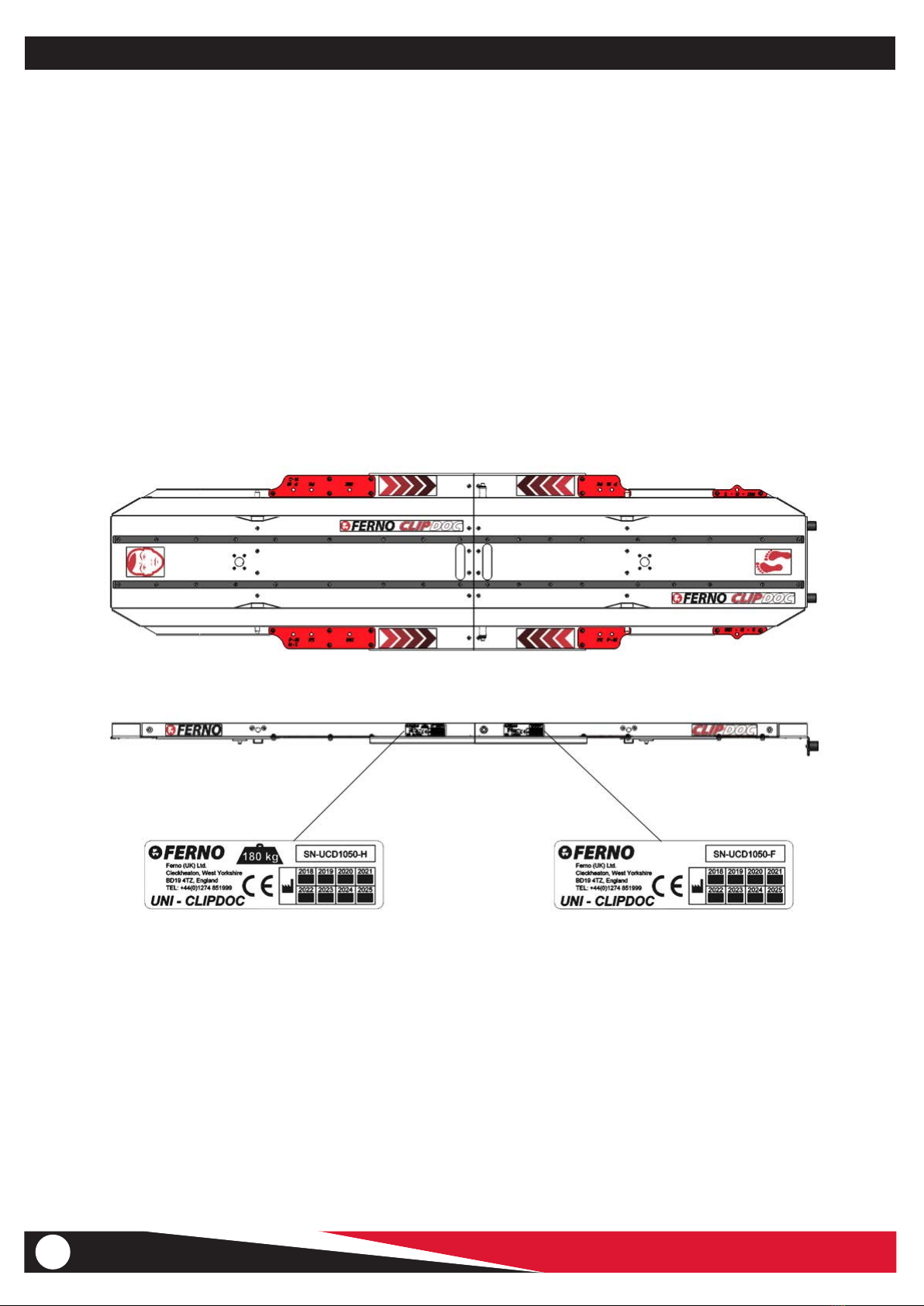
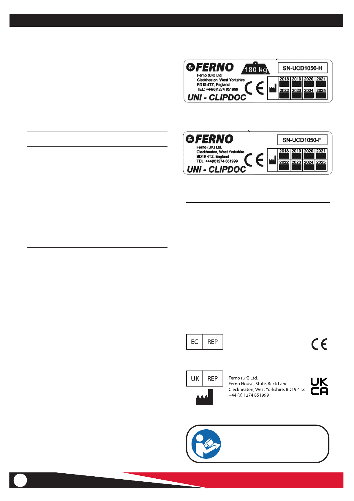
SERIAL Number plate 2 _________________________________
UNI-ClipDoc serial number(s) are marked on the manufacturer's
plates, which also includes the SWL in raised and lowered
position, date of manufacture and CE mark. The manufacturer's
plate on the side sections of each part.
SERIAL Number plate 1 _________________________________
FERNO S.r.l.
via B. Zallone, n. 26, 40066
Pieve di Cento, Bologna, Italy
+39.051.6860028

FERNO/MAN/0721/220-R2/UK 3
TABLE OF CONTENTS
Section Page
1 - Safety Information _______________________________ 4
1.1 Warnings ___________________________________ 4
1.2 Important Notices____________________________ 4
1.3 Cautions ___________________________________ 4
1.4 Trolley and Lock Compatibility with UNI-ClipDoc ___ 4
1.5 Safety and Instruction Labels ___________________ 5
1.6 Symbol Glossary _____________________________ 5
2 - Operator Skills and Training _______________________ 6
2.1 Skills_______________________________________ 6
2.2 Training ____________________________________ 6
3 - About UNI-ClipDoc _______________________________ 7
3.1 Product Overview ____________________________ 7
3.2 Auxiliary Bridging Plate _______________________ 7
4 - General Product Information ______________________ 8
4.1 Product Specications ________________________ 8
4.2 Serial number location ________________________ 8
4.3 UNI-ClipDoc Components and Storage___________ 9
5 - Operation of UNI-ClipDoc ________________________ 10
5.1 Daily checks________________________________ 10
5.2 Assembly of the UNI-ClipDoc__________________ 10
5.3 Installing the xing-bars______________________ 10
5.4 Installation using clamp xing-bars_____________ 11
5.5 Installation using ratchet-strap xing-bars _____12/13
5.6 Removal of xing-bars_______________________ 14
5.7 Emergency pin release _______________________ 15
5.8 Manual stop pins (If tted) ____________________ 15
6 - Spare Parts & Service ___________________________ 16
6.1 Spare Parts ________________________________ 16
6.1 Support Numbers ___________________________ 16
7 - Maintenance ___________________________________ 17
7.1 Maintenance Schedule_______________________ 17
7.2 Cleaning the UNI-ClipDoc ____________________ 17
7.3 Cleaning the Ambulance Trolley _______________ 17
7.4 Reattachment of Mattress and Restraints ________ 17
7.5 Lubrication of Trolley parts____________________ 17
7.6 Inspecting the Trolley and UNI-ClipDoc__________ 18

FERNO/MAN/0721/220-R2/UK
4
1 SAFETY INFORMATION
1.1 - Warnings
Warning notices indicate a potentially hazardous situation which,
if not avoided, could result in injury or death.
WARNING
Improper use of the UNI-ClipDoc can cause injury. Use the
UNI-ClipDoc only for the purpose described in this manual.
Untrained operators can cause injury or be injured. Permit
only trained personnel to operate the UNI-ClipDoc.
Improper operation can cause injury. Operate the UNI-
ClipDoc only as described in this manual.
An unattended patient can be injured. Stay with the
patient at all times.
Helpers can cause injury or be injured. Maintain control
of the UNI-ClipDoc, operate the controls and direct all
helpers.
Improper maintenance can cause injury. Maintain the
UNI-ClipDoc only as described in this manual.
Improper parts and service can cause injury. Use only
Ferno parts and Ferno-approved service on the UNI-
ClipDoc.
Modifying the UNI-ClipDoc can cause injury and damage.
Use the UNI-ClipDoc only as designed by Ferno.
Blood-borne Disease Notice
To reduce the risk of exposure to blood borne diseases such
as HIV-1 and hepatitis when using this product, follow the
disinfecting and cleaning instructions in this manual.
Safety Information
WARNING
Do NOT exceed the safe working loads of any Trolley
used with the UNI-ClipDoc.
1.4 - Trolley and Lock Compatibility in
conjunction with UNI-ClipDoc
UNI-ClipDoc has been dynamically crash-tested and certied to
BS EN 1789 when it is attached to a trolley using the supplied
cross bars, using one of the 2 types supplied, using the ratchet-
strap cross bars to attach to a trolley with tubular top-rail or using
the clamp cross bars to attach to the Ferno siderail interface on
trolleys such as PowerX and iNX.
Ferno's range of Ambulance trolleys have been tested and
certied in conjunction with Ferno's range of ambulance oor
locks.
Combining dierent manufacturers’ products into a “mixed-
component” trolley/fastener system can increase the user’s risk
of injury and damage if not checked rst for compatibility.
However, Ferno trolleys are designed to be compatible with
either the Ferno range of Two-part locking devices or competitors
equivalent locking devices, giving you full compatibility and
interchangeability across your eet.
1.2 - Important Notices
Important notices emphasise important usage or maintenance
information. Failure to follow Important notices could result in
damage to the product or property damage.
Bleach, phenols and iodine can cause damage. Do not apply
products containing these chemicals to the product.
Trapping hazards are unavoidable in the design of
UNI-ClipDoc due to its folding action. Operate with care.
1.3 - Cautions

FERNO/MAN/0721/220-R2/UK 5
1.5 - Safety and Instruction Labels
Safety and instruction labels place important information from
the user manual on the trolley.
Read and follow label instructions. Replace worn or damaged
labels immediately. New labels are available from your distributor.
1.6 - Symbol Glossary
The symbols dened below are used on the trolley and/or in this
user manual. Ferno uses symbols recognised by the International
Standards Organisation (ISO).
Pinch Point:
Keep Hands Clear
Safety Information
Manufacturer's plate
1 SAFETY INFORMATION
HEAD-END FOOT -END
Product meets UK and EU Standards

FERNO/MAN/0721/220-R2/UK
6
2 OPERATOR SKILLS AND TRAINING
2.1 - Skills
Operators using UNI-ClipDoc need:
● The strength, balance, coordination and common sense to
safely operate the equipment
● The ability to select the proper equipment and procedures
for the circumstances
● The ability to read, understand and follow the procedures
as described in this manual
● To have full training on the proper operation of the
equipment
● To have a working knowledge of manual handling
procedures
2.2 - Training
Operator trainees need to:
● Have followed a training plan
● Read and understand the instructions in this manual
● Practice using the fully-equipped equipment with weight
and under simulated conditions
● Trainees should be tested to verify their understanding of
UNI-ClipDoc operation
● Keep training records. Annual refresher training for all
operators is recommended
Operator Skills and Training
WARNING
Untrained operators can cause injury or be injured.
Permit only trained personnel to operate the
UNI-ClipDoc
WARNING
Improper use of the UNI-ClipDoc can cause injury.
Use the UNI-ClipDoc only for the purpose described
in this manual.

FERNO/MAN/0721/220-R2/UK 7
3 ABOUT THE UNICLIPDOC
About the UNI-ClipDoc
3.1 - Product Overview
UNI-ClipDoc is an interface designed to allow patient-carrying
equipment such as incubators and patient platforms like the
LifePort AeroSled TS to be transferred from a helicopter or aircraft
onto an ambulance trolley, providing a secure system to hold the
patient on the trolley, to then directly transfer into an Ambulance
for the remainder of the journey, thereby providing a safe and
seamless transport of patients by air and by road.
UNI-ClipDoc consists of two plates which attach together to
form a platform which can be attached to any of Ferno's range
of ambulance trolleys. The platform emulates the locking
mechanism on the oor of the air ambulance, thereby allowing
any patient platform that is used in an aircraft to be also locked
onto the top of an ambulance trolley.
The product is supplied with 2 dierent sets of "cross-member"
xing brackets, the rst set incorporating a ratchet mechanism,
allowing the UNI-ClipDoc to be attached to trolleys that have a
top-frame to attach to, such as Ferno's Pegasus, Megasus and
Harrier and Stryker's PowerPro TL.
The second xing bracket set incorporates a clamping mechanism
which allows the UNI-ClipDoc to be clamped to the integral
siderail interface on both PowerX and iNX trolleys, providing a
safe and quick method of attachment and detachment.
Assembly and attachment of the UNI-ClipDoc using the supplied
two sets of brackets is explained in detail later in this manual.
Procedure for attachment of the incubator or patient platform
to the UNI-ClipDoc follows the similar method of attaching to
the aircraft oor. Details of the platform locking mechanism are
explained in more detail.
All components are supplied in storage bags with carry handles,
allowing for easy storage, moving and access of the product as
and when required.
3.2 - Auxiliary Bridging plate (Optional)
Also available as an option for UNI-ClipDoc is a bridging plate, to
bridge the gap between aircraft oor and trolley where the trolley
cannot be brought directly up to the aircraft, facilitating transfer
directly from aircraft oor to UNI-ClipDoc without the need to lift
the patient platform. The bridging pate is available in dierent
lengths according to the gap that needs to be bridged.
Instructions on using the optional bridging plate are included
in a separate instruction sheet supplied with the bridging plate
itself as this may dier according to requirements.

FERNO/MAN/0721/220-R2/UK
8
4.0 GENERAL PRODUCT INFORMATION
UNI-ClipDoc
4.1 Product Specication
Overall length: 1955 mm
Overall width (Max. over clamp bars): 585 mm
Overall depth (Max. over clamp bars): 205 mm
Overall weight (full kit including carry bags): 32.3 kg (not including optional bridging plate)
Load capacity Refer to SWL of trolley
4.2 Serial number location
Serial number of the product is shown on the manufacturer's label, which is present on both sections of the UNI-
ClipDoc, as per the below diagram.

FERNO/MAN/0721/220-R2/UK 9
UNI-ClipDoc
4.0 GENERAL PRODUCT INFORMATION
4.3 UNI-ClipDoc Components and Storage
It is important that the various Uni Clip Doc components
are all stored according to the instructions above to avoid
parts going missing or getting mixed up with other UNI-
ClipDoc units.
Each UNI-ClipDoc half-section has its own storage bag.
The serial number of each section is also displayed on the
outside of the bag. The two types of xing bars (clamp and
ratcheting) are stored in separate bags with the name of
the xing-bars displayed on the side.

FERNO/MAN/0721/220-R2/UK
10
5.1 Daily pre-checks
• Prior to using ensure to check the overall condition
of the unit for any signs of damage / missing parts
• Check for correct operation of the emergency
release pins
• Check for correct operation of the clamp xing-bars
and look for any signs of damage / wear
• Check for correct operation of the ratcheting xing
bars and look for any signs of damage / wear
• Check the condition of the straps. Replace if any
damage is found
• Check for loose / missing hardware. Tighten/replace
where necessary
5.2 Assembly of UNI-ClipDoc
UNI-ClipDoc can be split into two sections to aid storage
and transport when not in use. Assembly / dis-assembly
of the UNI-ClipDoc requires two operators and does not
require the use of any tools. The UNI-ClipDoc should be
assembled on a smooth, level surface and debris gloves
should be worn to avoid any possible operator injury.
• Remove the two halves of the
UNI-ClipDoc from their storage
bags and check all items are
present and in good condition
before proceeding. Each
section is marked to denote
head-end and foot-end.
• Stand the foot-end section of
the unit upright on the rubber
feet.
• Whilst the rst operator holds
the foot-end section upright,
the second operator can then
lift the head-end section up
and insert the black spigots
into the sockets on the foot-
end section.
• Keeping ngers clear, push
down on the head-end section
to ensure the pegs are fully
inserted and no gap exists
between the two sections.
• Insert the spring loaded
locking pins (one on each side)
5.0 OPERATION OF UNICLIPDOC
TO PREPARE THE AMBULANCE TROLLEY FOR
INSTALLATION OF THE UNI-CLIP DOC:
• APPLY THE BRAKES TO PREVENT THE
TROLLEY FROM MOVING DURING
INSTALLATION
• REMOVE THE PATIENT HARNESS AND LEG
RESTRAINTS
• REMOVE THE MATTRESS
• FOLD THE COTSIDES/ SURFACE EXTENDERS
INTO THE VERTICAL DOWN POSITION
• LOWER THE BACK REST AND LEG RAISE
PANELS INTO THE FULLY FLAT POSITIONS
• REMOVE ANY OTHER ACCESSORIES WHICH
MAY INTERFEREWITH CORRECT OPERATION
OF THE UNI-CLIP DOC
5.3 Installing the xing-bars
First determine the type of xing-bar required depending
on the model of trolley to be used for transport. Using the
installation drawing and the position labels on the UNI-
ClipDoc itself, determine the correct positions where the
xing -bars should be attached to the UNI-ClipDoc, which
is dependant on the trolley type being used.
The abbreviated trolley names etched onto the
UNI-ClipDoc are as follows:
P = FERNO PEGASUS
M = FERNO MEGASUS
H = FERNO HARRIER / HARRIER LT
PX = FERNO POWERX
INX = FERNO INX
S = STRYKER POWER PRO
Both variants of xing bar attach to the
UNI-ClipDoc in the same manner, using two
thumbscrews per xing-bar
Tighten the thumbscrews by hand only. Do
not use tools to tighten the thumbscrews
UNI-ClipDoc

FERNO/MAN/0721/220-R2/UK 11
5.0 OPERATION
5.4 Installation using clamp
xing-bars
The clamp xing-bars are used when attaching the UNI-ClipDoc to Ferno PowerX or iNX trolleys. The clamp
xing-bars have three dierent congurations. The correct congurations required for installation on the
various trolleys are shown below.
When installing on the PowerX trolley, the clip-on spacer marked “PowerX” should be installed on both the
head-end and foot-end xing-bars.
To install the clip-on spacers, align the three pegs with the sockets and push down into place.
To remove the clip-on spacers, simply pull up to release the three pegs from the sockets.
When installing on an INX trolley, remove all clip-on spacers from one xing-bar and install at the foot-end.
For the head-end xing bar, remove the PowerX spacer and install the clip-on spacer marked INX head-end
and position this bar at the head-end of the trolley.
UNI-ClipDoc

FERNO/MAN/0721/220-R2/UK
12
5.0 OPERATION
5.4 Installation using clamp
xing-bars (cont....
Once the cross bars are in the correct conguration, they
can be attached to the Uni-ClipDoc in the appropriate
positions for the trolley being used (see section 5.3).
To unlock the clamps, lift the sliding lock plates up as
pictured below. Oer the Uni-Clip doc up to the trolley
and position centrally across the length and width.
Push down on the Uni-ClipDoc to locate the clamps on the
side rail of the trolley.
Close all four clamps, push down on the sliding lock plates
until they click into the locked position.
The Uni-ClipDoc is now ready for use.
UNI-ClipDoc
FIG 1 FIG 2
FIG 3 FIG 4
5.5 Installation using the ratcheting xing-bars
With the ratcheting xing-bars installed in the appropriate positions, oer the UNI-ClipDoc up to
the trolley and position it centrally across the length and width of the trolley top.
Unlock the ratchet mechanism by lifting the lever marked "Release" and rotate the ratchet lever
down fully.
Pull on the tang- end of the strap to release tension from the ratchet and provide enough slack to
allow feeding of the strap around the trolley siderail.
Feed the end of the strap with the tang attached around the back of the trolley side rail,
underneath and then back up the front of the siderail.

FERNO/MAN/0721/220-R2/UK 13
5.5 Installation using the ratcheting xing-bars (cont...)
NOTE: THE STRAP MUST BE FED AROUND THE MAIN SIDE RAIL ONLY. DO NOT WRAP THE
STRAP AROUND ANY OTHER PART OF THE TROLLEY
Hook the tang onto one of the two xing points on the UNI-ClipDoc xing-bar.
Pull on the loose end of the strap to take up the slack.
NOTE: TO PREVENT MALFUNCTION OF THE RATCHET MECHANISM ENSURE THE SLACK IS
PULLED OUT OF THE STRAP AS SHOWN IN FIG 7 BEFORE RATCHETING THE LEVER.
Begin ratcheting the lever to tighten the strap. Do not tighten fully at this stage.
Repeat the above on all four ratchet straps.
When all ratchet straps are moderately tight, go around and fully tighten all four ratchets to
complete the installation.
5.0 OPERATION
UNI-ClipDoc
FIG 5 FIG 6
FIG 7 FIG 8
FIG 9 NOTE: ENSURE ALL FOUR RATCHET HANDLES ARE IN
THE VERTICAL, LOCKED, POSITION BEFORE USE
The Uni-ClipDoc is now ready for use.

FERNO/MAN/0721/220-R2/UK
14
UNI-ClipDoc
5.6 Removal of xing-bars
Unlock the ratchet mechanism by lifting the lever marked release and rotate the ratchet lever
down fully.
Take hold of the strap just below the tang (as shown above) and pull rmly to release the tension.
The tang can then be removed from the xing point. The strap can be left hanging freely as the
Uni-ClipDoc is lifted clear of the trolley. Remember to return the ratchet handle to the locked
position to prevent damage during storage.
FIG 10 FIG 11
FIG 12 FIG 13
FIG 14 FIG 15 FIG 16
5.0 OPERATION

FERNO/MAN/0721/220-R2/UK 15
5.7 Emergency pin release
The UNI-ClipDoc features an emergency pin release system to be used if the locking pins on the
incubator / AeroSled are damaged in an accident or get stuck in the locked position. To release
stuck locking pins, apply force / use a blunt object to drive the four spring loaded release pins
as shown below. These in turn will force the jammed pins of the Incubator / Aero Sled clear of
the location blocks so the unit can be removed from the UNI-ClipDoc.
5.8 Manual stop pins (if tted)
As a safety precaution when transporting an incubator, the UNI-ClipDoc features two safety
pins which clip in to the unit, one at each end of the incubator. These act as a fail-safe and
prevent the incubator sliding out should the pins in the incubator fail to locate into the pin
blocks. These pins simply push in to install and pull out to remove.
5.0 OPERATION
UNI-ClipDoc

FERNO/MAN/0721/220-R2/UK
16
UNI-ClipDoc Parts and Service
6.0 SPARE PARTS, SERVICE
6.1 Spare Parts
Below are the Part Numbers and names of parts available to maintain your UNI-ClipDoc
6.2 UK Support Numbers
In the United Kingdom to order parts or for professional repair,
contact Ferno UK - the only agent authorised by Ferno UK to
manage, service, and repair Ferno products.
elephone Main Reception +44 (0)1274 851999
Service Department +44 (0)1274 854511
Web www.ferno.co.uk
WARNING
Improper parts and service can cause injury. Use
only Ferno parts and Ferno-approved service on
the UNI-ClipDoc.

FERNO/MAN/0721/220-R2/UK 17
Maintenance
7 MAINTENANCE
7.1 - Maintenance Schedule
The Uni-ClipDoc and Ambulance trolley used both require regular
preventative maintenance. Set up and follow a maintenance
schedule. The table at right/below represents minimum intervals
for maintenance.
It is suggested that the Ambulance trolley and UNI-ClipDoc used
for a transportation is visually inspected after every completed
patient transfer.
Keep maintenance records. A sample maintenance record sheet is
provided at the end of this manual.
When using maintenance products, follow the manufacturers’
directions and read the manufacturers’ material safety data sheets.
You can purchase a recommended disinfectant from your Ferno
distributor or Ferno UK Service Department.
7.2 - Disinfection of UNI-ClipDOC
Clean the unit and component parts regularly using warm water
and a mild soap or detergent.
Do not use high pressure washers
Wipe all surfaces with disinfectant. Follow the disinfectant
manufacturer’s instructions for application method and contact
time. Ferno recommends you inspect the equipment for damage
as you clean or disinfect it.
Minimum
Maintenance Intervals
Each Use
As Needed
Each Month
Disinfecting •
Cleaning •
Inspecting • •
Lubricating (trolley) •
IMPORTANT
Disinfectants and cleaners containing bleach, phenolic, or
iodine can cause damage. Do not use products containing
these chemicals.
7.3 - Cleaning the Ambulance Trolley
Regular cleaning helps reduce the risk of transmitting disease and
enables equipment to function at its optimum.
Steam cleaning or power washing of the trolley with a suitable
cleaning additive is the most eective method of cleaning.
Although sealed to IPX6 rating, avoid spraying directly onto
the electrical components. When using a steam cleaner or jet
wash, ensure to operate at a safe working distance and with the
cleaning nozzle at all times positioned at least 8inch / 20cm from
the surface being cleaned, using water at a temperature no more
than 60ºC / 140ºF.
Wipe all surfaces with disinfectant. Follow the disinfectant
manufacturer’s instructions for application method and contact
time. Ferno recommends you inspect the trolley for damage as
you clean and disinfect it.
1. Remove the mattress, restraints and any accessories.
2. Hand clean all surfaces of the trolley with warm water and a
mild detergent.
3. Rinse with warm, clear water. Dry the trolley with a towel
and allow it to air-dry thoroughly, replacing the mattress and
harness/restraints prior to storage.
Once cleaned, dry the trolley with a soft towel, paying particular
attention to swivel and sliding joints. If a compressed air hose is
available, you may nd that compressed air jets are more eective
in drying the hard-to-reach places.
7.4 - Reattachment of Mattress and
Restraints after using UNI-ClipDoc
Ensure that the mattress and trolley patient restraints are placed
back on the trolley after each patient transfer using UNI-ClipDoc
has been completed. Take extra care to ensure that the restraint
straps are correctly re-attached to the trolley.
7.5 - Lubrication of Trolley parts
Disinfect and clean the trolley before applying lubricant. Use
the lubricants designated below to lubricate the trolley. Do not
lubricate points marked with the “do not lubricate”symbol.
Your Ferno Trolley will work eciently and safely only when it is
lubricated. You MUST lubricate all moving and sliding parts after
every inspection or preventative maintenance programme, or if
there is inadequate lubrication for the moving parts to operate
easily and quietly.
In general terms, almost all sliding and moving parts may be
lubricated with light duty grease. A penetrating uid lubrication
is used on some sliding parts of the trolley. However, when a
penetrating uid lubricant is used, all excess MUST be wiped
away, to prevent any build-up of dust or grime which can clog up
working parts and impede movement.
Do Not Lubricate Lubricate
IMPORTANT
Lubricating parts that should not be lubricated allows
dirt and foreign particles to collect on those parts,
resulting in damage. Lubricate only the numbered
reference points shown.
WARNING
Improper maintenance can cause injury. Maintain the
trolley and UNI-ClipDoc only as described in this manual.

FERNO/MAN/0721/220-R2/UK
18
7 MAINTENANCE
Maintenance
INSPECTION CHECKLIST TICK
● Are all components present? ________________________________________________________________________
● Is the trolley and UNI-ClipDoc generally free of excessive wear? ____________________________________________
● Are all screws, nuts, bolts and rivets securely in place? ___________________________________________________
● Do all moving parts operate smoothly and properly? ____________________________________________________
● Does the trolley raise and lower properly into position with UNI-ClipDoc attached? ___________________________
● Does the trolley move smoothly?____________________________________________________________________
● Do the wheel castors and brake operate properly, rotate fully and have adequate tread? _______________________
● For powered trolleys check that the battery is tted to the trolley and that it is fully charged
at the beginning of each shift ______________________________________________________________________
● Press the button located on the battery and check the red LED’s light up test the battery and ensure it is ready to use.
● Conrm the operation of the trolley by using the up/down control buttons on the foot-end main frame. __________
● Check that the trolley cotsides raise, lower and lock in position.____________________________________________
● Check that the ambulance has a properly installed, approved locking device and that the trolley locks in securely.__
● Check the operation of the push/pull handles and push poles _____________________________________________
7.6 - Inspecting the Trolley and UNI-ClipDoc before use
To ensure consistently safe operation of the trolley and UNI-ClipDoc interface and to monitor wear and tear, prior to each use, ensure the
trolley is thoroughly checked in compliance with the following checklist.
Table of contents
Other Ferno Mobility Aid manuals
Popular Mobility Aid manuals by other brands

Enable Lifecare
Enable Lifecare Oxford Up User instruction manual

OWL
OWL OAKWORKS Vitrectomy RecoverySeated Support instruction manual

Pressalit
Pressalit PLUS Mounting instruction

Invacare
Invacare H407 Omega operating instructions

Mopedia
Mopedia GAYA 2.0 instruction manual

Circle Specialty
Circle Specialty Klip Posterior KP410B user manual