ALFRA TML 500 User manual

Bruksanvisning
/ Operation manual
ALFRA TML 500
Lyftmagnet
Lifting Magnet
Artikelnummer 41500 / Prod.-No. 41500

2
Innehåll / Contents
Säkerhetsanvisningar, Korrekt användning, Enhetsbeskrivning,
Tekniska data, Markeringar på lyftmagneten, Idrifttagning,
Svängning eller vertikal lyftning av laster, Justerbar stötdämpare,
Grundläggande information, Underhåll och inspektion, Detaljerad
prestandadata, EG-försäkran om överensstämmelse
Före användning,
läs och spara
denna
bruksanvisning!
Sida 3
Safety instructions, Proper use, Device description, Technical
data, Markings on the lifting magnet, Start-up, Pivoting or vertical
lifting of loads, Adjustable shock absorber, Basic information,
Maintenance and inspection, Detailed performance data, EC
Declaration of Conformity
Before use read
and save these
instructions! Page 12
English
Svenska

3
Säkerhetsinstruktioner
Fara kan uppstå vid transport av last med lyftanordningar på grund av felaktig användning och / eller dåligt
underhåll, vilket kan orsaka allvarliga olyckor och allvarliga skador eller till och med dödsfall. Läs och följ bruks-
och säkerhetsinformationen i denna bruksanvisning mycket noggrant. Kontakta tillverkaren om du har några
frågor.
Alltid...
aktivera lyftmagneten helt
aktivera lyftmagneten på metalliska, ferromagnetiska material
använd hela den magnetiska ytan för att lyfta
lyft på plana ytor
kontrollera den magnetiska hållkraften genom att lyfta lasten något med cirka 10 cm
rengör den magnetiska ytan och håll den fri från smuts, flis, svetsstänk
sätt ner lyftmagneten försiktigt för att förhindra skador på magnetytan
kontrollera riskområdet innan du svänger lasten
respektera den angivna maximala belastningen före svängning
inspektera den magnetiska ytan och hela lyftmagneten för skador
använd lämpliga lyftanordningar
följ instruktionerna i bruksanvisningen
instruera nya operatörer i säker användning av lyftmagneter och läs lokala och
landsspecifika riktlinjer
förvaras och används i torr miljö
Aldrig...
lyft runt eller välvda föremål
överstiga den angivna maximala belastningen
lyft last över människor
lyft mer än ett arbetsstycke åt gången
stäng av lyftmagneten innan du sätter ner lasten säkert
låt lasten gunga eller stoppa omedelbart
lyft laster som överstiger de rekommenderade måtten
lyft last med håligheter, utskurna öppningar eller borrade hål
lyft obalanserade laster
modifiera lyftmagneten eller ta bort manövreringsetiketter
använd lyftmagneten om delar är skadade eller saknas
skada magnetens undersida genom yttre våld
placera dig under den lyfta lasten
lyft last medan människor befinner sig inom riskområdet
lämna den lyfta lasten utan uppsikt
använd lyftmagneten utan att ha instruerats ordentligt
använd om du inte har läst och förstått denna bruksanvisning helt
använd lyftmagneten för att stödja, lyfta eller transportera personer
använd lyftmagneten vid temperaturer över 60 ° C (140 ° F)
utsätta lyftmagneten för frätande ämnen
Personer som använder pacemaker eller annan medicinsk utrustning bör inte
använda denna lyftmagnet förrän de har rådfrågat sin läkare.

4
Korrekt användning
Den permanenta lyftmagneten TML 500 är konstruerad för att lyfta laster av ferromagnetiska metaller och får
endast användas enligt dess tekniska data och bestämning. Korrekt användning innefattar också att de start-,
drift-, miljö- och underhållsförhållanden som anges av tillverkaren följs. Korrekt användning och underhåll av
lyftmagneten är användarens ansvar. Det är också dennes ansvar att förstå driftsinstruktionerna.
Enhetsbeskrivning
TML 500 (Thin Material Lifter) är en omkopplingsbar lyftmagnet med manuell manövrering för lyft, transport och
sänkning av ferromagnetiska material. Genom att trycka ner spaken (F) kan magnetfältet som genereras av
permanentmagneten aktiveras i det nedre magnetplattans (C) område.
Tack vare den speciella designen genereras ett mycket kompakt magnetfält som utvecklar utmärkt
vidhäftningskraft, särskilt på tunna material (mindre än 10 mm). Magneten kan deaktiveras genom att först trycka
på säkerhetsfliken (E) med handen och sedan föra spaken uppåt. Ett justerbart oljespjäll är infört under
säkerhetslocket för att absorbera rekylenergin i spaken, särskilt vid användning på tunna material. Ytterligare
gängor för montering är placerade på vardera framsidan av magneten som, om så önskas, kan användas som
hållaranordning. En ögla är placerad på toppen av lyftmagneten för fastsättning på en kran. Lyftmagnetens
bärförmåga motsvarar 1/3 av magnetens maximala brytkraft och motsvarar därmed standard säkerhetsfaktor 3: 1.
A) Lastkrok
B) Grundkropp
C) Magnetisk kontaktyta
D) Magnetens mitt
E) Säkerhetslock
F) Spak för aktivering / avaktivering
G) Stötdämpare för spak
H) Ytterligare gängor för montering

5
Teknisk data
Artikelnummer
41500
Beteckning: TML 500 Lyftmagnet
Brytande kraft:
Max. bärförmåga: (på platt
material med säkerhetsfaktor
3: 1)
>1500 kg från 15 mm S235
500 kg från 15 mm S235
>3300 lbs från ½” AISI CRS 1020
1100 lbs från ½” AISI CRS 1020
Max. bärförmåga: (vid 6 °
lutning enligt EN 13155 med
säkerhetsfaktor 3: 1)
440 kg från 15 mm S235 950 lbs från ½” AISI CRS 1020
Max. bärförmåga: (vid 90 °
lutning av lasten med
säkerhetsfaktor 3: 1)
150 kg från 15 mm S235 330 lbs från ½” AISI CRS 1020
Magnetens dödvikt:
7,3 kg
16 lbs
Förvaringstemperatur: -22°F till +140°F
Arbetstemperatur:
-30°C till +60°C
-10°C till +60°C +14°F till +140°F
Markeringar på lyftmagneten
Ytterligare detaljerade beskrivningar för hanterings- och driftsförhållanden finns på båda sidor om lyftmagneten.
Denna märkning får inte ändras, skadas eller tas bort, eftersom tillverkaren annars inte kan hållas ansvarig för
personskador, egendomsskador eller olyckor till följd av detta. Nya etiketter måste beställas från tillverkaren vid
behov.

6
Börja
Du har fått en helt monterad lyftmagnet och detaljerad bruksanvisning. Kontrollera varornas skick vid
mottagandet för eventuella skador som uppkommit under transporten och se till att leveransen är komplett.
Kontakta omedelbart en auktoriserad återförsäljare eller tillverkare om du har några problem.
Var noga med att läsa bruksanvisningen helt innan du använder magneten för första gången!
1. Spaken är vänd uppåt. Lyftmagneten är avaktiverad.
2. Följ säkerhetsanvisningarna. Rengör arbetsstycket och den nedre magnetplattan på lyftmagneten.
3. Placera lyftmagneten vid lastens tyngdpunkt. Lyftmagneten är förspänd något för att undvika oavsiktlig glidning
och/eller tappning av magneten (t.ex. när den används i vertikal eller annan påtvingad position).
4. Rikta in lyftmagneten perfekt efter önskad applikation.
5. Tryck ned spaken tills den är helt i läge ON. Se till att säkerhetsspärren sitter ordentligt på plats.
6. Flytta lastkroken till önskat läge och lyft lasten med cirka 10 mm för att kontrollera dess deformation och
magnetiska hållkraft.
7. Flytta nu din last långsamt och smidigt. Undvik att gunga eller skaka.
8. Efter att lasten har ställts ner helt och säkert kan du inaktivera lyftmagneten. För att göra detta, tryck på
säkerhetspärren med handens och för spaken uppåt till OFF-läget.

7
Svängbar eller vertikal lyftning av laster
TML500-lyftmagnetens speciella design gör det möjligt för användaren att vrida och svänga lasten fritt. Den
hängande lasten kan vändas 360 ° och svängas vid 90 ° i de flesta fall.
1. Var noga med att använda ett flexibelt mjukt ögla för att undvika att klämma fast lyftmagneten i kranens krok,
eftersom detta skulle leda till extremt ogynnsamma lastförhållanden och lyftkapaciteten inte längre garanteras.
Dessutom skyddar detta din magnet från skador och förlänger dess livslängd.
2. Om lasten är fäst horisontellt på magneten, verkar hela lyftmagnetens brytkraft på lasten, så att du kan
använda 100% av lyftkapaciteten enligt tabell 2. Men om lasten och magneten lutning i en annan vinkel än 0 ° mot
horisontell, minskar den bärande kapaciteten på grund av magnetens nya inriktning mot jordens tyngdkraft. Så
snart lasten är upphängd vertikalt, dvs. i en vinkel på 90 °, kommer friktion att vara den enda effekten som utövas
av magneten, som inte är mer än 10-35% av den maximala bärförmågan, beroende på vilket material som lyfts.
Lastsiffror som motsvarar riktningen på TML 500
Du kan beräkna magnetens maximala bärförmåga, inklusive säkerhetsfaktorn 3: 1, utifrån den belastningsfigur
som motsvarar riktningen.
Figur 1 Figur 2

8
Exempel mm:
Du vill lyfta en platta som är 6 mm tjock och gjord av S235. Plattan står vertikalt, dvs. i en vinkel
90 °, i ditt hyllställ och din magnet är idealiskt placerad, som visas i figur 1.
Materialtjocklek:
Material: 6 mm max. bärförmåga vid 0 ° = 360 kg (se tabell 2)
S235 hållkraft, föremål för material = 100% (se tabell 1)
Lastens inriktning: 90 ° lutad; lastkroken vänd uppåt
Lastsiffra motsvarande riktning = 30%
Exempel INCH:
Du vill lyfta en tallrik av milt kallvalsat stål (CRS) som är 1/4 tum tjockt. Plattan står vertikalt, dvs. i en vinkel på
90 °, i din hyllställ och din magnet är idealiskt placerad, som visas i figur 1.
Materialtjocklek:
Material: 1/4 inch max. bärförmåga vid 0 ° = 800 kg (se tabell 2)
S235 hållfasthet av milt stål, föremål för material = 100% (se tabell 1)
Lastens inriktning: 90 ° lutad; lastkroken vänd uppåt
last-siffra motsvarande riktning = 30%
Max lastvikt med 3: 1 säkerhetsfaktor = 360 kg x 100% x 33% = 120 kg
Maximal vikt med 3: 1 säkerhetsfaktor = 800 kg x 100% x 33% = 264 kg
Justerbar stötdämpare
En oljefylld stötdämpare är inbyggd på baksidan av magneten för att absorbera eventuell rekylenergi hos
spaken. Ju tunnare materialet som ska lyftas, desto högre kommer rekylenergin att absorberas. Ställskruven på
baksidan av magneten gör det möjligt att justera stötdämparen variabelt, så att spakens uppåtrörelse är
kontrollerad och fungerar smidigt. Denna justering bör göras med en skruvmejsel.

9
Grundläggande information om hantering av magnetiska lyftredskap
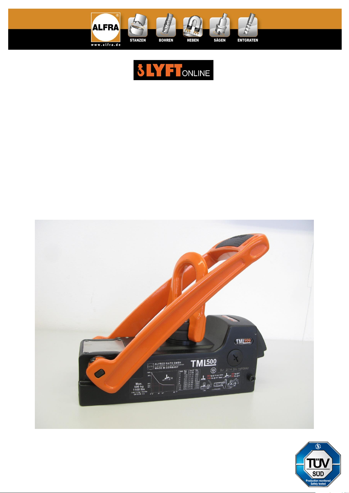
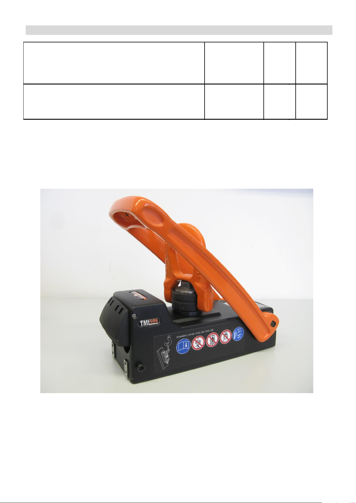
särskilt TML
Den magnetiska ytan är placerad på undersidan av lyftmagneten och innehåller flera magnetiska poler som
genererar den magnetiska hållkraften när den aktiveras. Den maximala hållkraften som kan uppnås beror på olika
faktorer som förklaras nedan:
Materialtjocklek
Lyftmagnetens magnetiska flöde kräver en minimal materialtjocklek för att strömma helt in i lasten. Under denna
minsta materialtjocklek minskas den maximala hållkraften beroende på materialtjockleken. Konventionella
omkopplingsbara permanentmagneter har ett djupt penetrerande magnetfält som liknar trädkranrötter och kräver
en stor materialtjocklek för att uppnå maximal hållkraft. TML-magnets kompakta magnetfält liknar en grund rot och
uppnår maximal hållkraft även när den används på tunna material (se tabell 2 i denna bruksanvisning).
Material
Varje material reagerar på olika sätt vid inträngning av magnetfältlinjerna. Lyftmagneternas bärförmåga bestäms
med hjälp av ett koldioxidsnålt material. Stål med högt kolinnehåll eller vars struktur har förändrats genom
värmebehandling har en lägre hållkraft. Skumade eller porösa gjutna komponenter har också en lägre hållkraft så
att lyftmagnetens givna bärförmåga kan nedgraderas på basis av följande tabell 1.
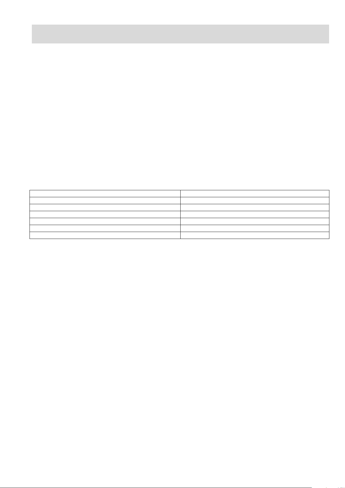
Tabell 1
Material
Magnetisk kraft i%
Olegerat stål (0,1-0,3% C-innehåll)
100
Olegerat stål (0,3-0,5% C-innehåll)
90-95
Gjutstål
90
Grått gjutjärn
45
Nickel
11
De flesta rostfria stål, aluminium, mässing
0
Ytkvalitet
Den maximala hållkraften hos en lyftmagnet kan uppnås i händelse av en sluten magnetisk krets där
magnetfältlinjerna kan anslutas fritt mellan polerna, vilket skapar ett högt magnetiskt flöde. Till skillnad från
exempelvis järn har luft mycket högt motstånd mot magnetiskt flöde. Om ett slags ”luftspalt” bildas mellan
lyftmagneten och arbetsstycket minskas hållkraften. På samma sätt utgör färg, rost, ytbeläggningar, fett eller
liknande ämnen alla ett utrymme eller ett luftspalt mellan arbetsstycket och lyftmagneten. En ökning av ytjämnhet
eller ojämnhet påverkar också den magnetiska hållkraften. Referensvärden finns i prestandatabellen för din
lyftmagnet.
Lastmått
När du arbetar med stora arbetsstycken som balkar eller plattor kan lasten deformeras under lyften. En stor stålplåt
skulle böjas nedåt vid ytterkanterna och skapa en krökt yta som inte längre har full kontakt med magnetens botten.
Den resulterande luftspalten minskar lyftmagnetens maximala bärförmåga. Ihåliga föremål eller de som är mindre
än den magnetiska ytan kommer också att resultera i mindre hållkraft.
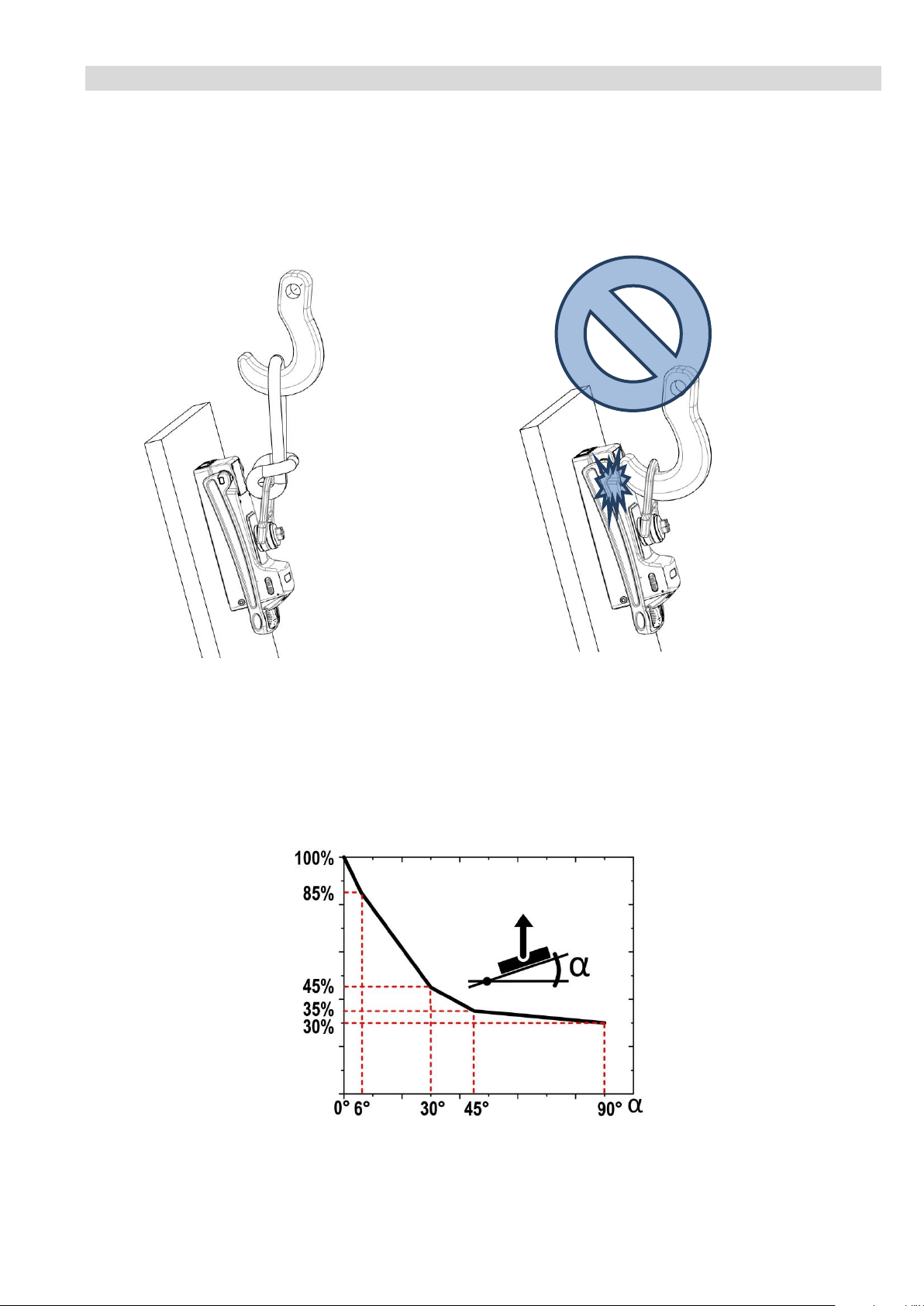
Lastjustering
Under lasttransport måste man se till att lyftmagneten alltid är i arbetsstyckets tyngdpunkt och att lasten respektive
lyftmagneten alltid är horisontellt inriktad. I det här fallet verkar lyftarens magnetiska kraft med sin utlösningskraft
vinkelrätt i förhållande till ytan, och den maximala nominella bärförmågan uppnås med 3: 1 standard
säkerhetsfaktor.
Om arbetsstyckets och lyftmagnetens läge ändras från horisontellt till vertikalt, körs lyftmagneten i skjuvläge och
arbetsstycket kan glida bort åt sidan. I skjuvläge minskar den bärande kapaciteten beroende på
friktionskoefficienten mellan de två materialen.
Temperatur
De högeffektiva permanentmagneterna som installeras i lyftmagneten kommer att förlora sina magnetiska
egenskaper oåterkalleligt från en temperatur över 80 ° C (180 ° F), så att den fulla bärförmågan aldrig uppnås igen
även efter magneten har svalnat. Observera specifikationerna på din produkt eller i bruksanvisningen.

10
Underhåll och inspektion av lyftmagneten
Användaren är skyldig att underhålla och serva lyftmagneten i enlighet med specifikationerna i
bruksanvisningen och i enlighet med landsspecifika standarder och föreskrifter (t.ex. ASME B30.20B, DGUV-
Information 209-013; AMVO).
Underhållsintervallen klassificeras enligt det rekommenderade schemat.
Före varje användning ...
inspektera lyftmagneten visuellt för skador
rengör ytan på arbetsstycket och magnetens undersida
frigör undersidan av magneten från rost, flis eller ojämnhet
verifiera låsfunktionen på säkerhetspärren på spaken
Varje vecka...
inspektera lyftmagneten och lastkroken för deformation, sprickor eller andra defekter
se till att manöverspaken och säkerhetsspärren fungerar som de ska
inspektera lastkroken för skador eller slitage och byt ut den vid behov
inspektera magnetens botten för repor, tryckpunkter eller sprickor och reparera magneten
vid behov
En gång i månaden...
kontrollera märkningen på lyftmagneten med avseende på läsbarhet och skador och byt ut
dem vid behov
Årligen...
kontrollera lyftmagnetens bärförmåga av leverantören eller en auktoriserad verkstad
Obehöriga reparationer eller modifieringar av lyftmagneten är inte tillåtna.
Kontakta tillverkaren om du har några frågor.
En årlig inspektion rekommenderas för säker användning av denna lyftmagnet. Vi kommer gärna att utföra
denna inspektion för dig internt. Vänligen skicka ett mejl till:
Du kommer då omedelbart att få ett erbjudande och försäkra dig om att lyftmagneten kommer att inspekteras
på ett pålitligt.

11
Detaljerad prestandadata för TML 500 lyftmagnet
Värden som visas för lastkapacitet är baserade på material S235 JR jämförbart med AISI 1020 kallvalsat stål med
maximal, vertikal brytkraft vid 0 ° avvikelse från lastaxeln och dessutom under en 6 ° lutande belastning enligt EN
13155 med en 3: 1 säkerhetsfaktor. Denna bruksanvisning innehåller inga instruktioner för användning på runt
material, eftersom TML 500 är konstruerad för platt material och runda material eller välvda föremål får inte lyftas.
Tabell 2
Lastkapacitet i kg
Tjocklek på
material
Ren, plan,
markyta
Rostig, lätt
repad yta Oregelbunden,
rostig eller grov
yta
Luftspalt <0,1 mm
Luftspalt =0,25 mm
Luftspalt =0,5 mm
mm
0°
6°
0°
6°
0°
6°
2
50
44
45
39
40
35
3
130
110
115
100
85
72
4
195
170
160
140
135
115
5
300
260
240
205
190
165
6
360
315
270
235
220
190
8
455
395
310
270
240
205
10
490
430
360
310
260
225
15
500
440
365
315
250
215
>20
500
440
370
320
250
220
Lastkapacitet i lbs
Tjocklek på
material
Ren, plan,
markyta
Rostig, lätt
repad yta
Oregelbunden,
rostig eller grov
yta
Luftspalt <0,004 inch
Luftspalt =0,01 inch
Luftspalt =0,02 inch
inch
0°
6°
0°
6°
0°
6°
0,08
110
90
100
85
90
75
0,12
285
245
255
220
185
160
0,16
430
370
355
305
295
255
0,20
660
575
525
455
415
360
0,25
800
575
595
510
480
415
0,30
1000
870
685
590
525
455
0,40
1090
940
785
680
540
470
0,50
1100
950
800
690
545
475
>1
1100
970
815
705
555
480
De maximala dimensionerna för de laster som ska lyftas beror till stor del på arbetsstyckens geometri och
böjstyvhet. Om materialet böjs bildas en luftspalt under den magnetiska ytan vilket minskar den bärande
kapaciteten avsevärt. Under varje lyft, titta efter eventuell deformation av arbetsstycket som kan uppstå och
kontrollera vid behov om luftspalten utvecklas vid kanterna på den TiN-belagda magnetytan (t.ex. med ett
pappersark; 80 g / m2). Fördelarstänger med ytterligare magneter kan krävas för att säkert lyfta stora eller
flexibla laster.
Stanna omedelbart lyftet om det finns överdriven deformation eller en luftspalt.
Överskrid aldrig dimensionerna och / eller bärförmågan för materialtjockleken som
anges i tabell 2.

12
Safety instructions
Danger can occur when transporting loads by lifting devices due to improper use and/or poor maintenance, which
may cause severe accidents and serious injury or even death. Read and follow the operation and safety
information contained in this operating manual very carefully. If you have any questions, contact the manufacturer.
Always...
activate the lifting magnet completely
activate the lifting magnet on metallic, ferromagnetic materials
use the entire magnetic surface for lifting
lift on plane surfaces
check the magnetic holding force by lifting the load slightly by about 10 cm
clean the magnetic surface and keep it clear of dirt, chips, welding spatter
set the lifting magnet down gently to prevent damage to the magnetic surface
check the hazard area before pivoting the load
respect the stated maximum load before pivoting
inspect the magnetic surface and the entire lifting magnet for damage
use suitable lifting devices
follow the instructions in the operating manual
instruct new operators in the safe use of lifting magnets and read respect local and country-
specific guidelines
keep and use in a dry environment
Never...
lift round or arched objects
exceed the stated maximum load
lift loads over people
lift more than one work piece at a time
switch the lifting magnet off before setting down the load safely
allow the load to sway or bring to a sharp and immediate stop
lift loads exceeding the recommended dimensions
lift loads with cavities, cut-out openings or drilled holes
lift unbalanced loads
modify the lifting magnet or remove operating labels
use the lifting magnet if damaged or missing parts
strain the underside of the magnet through heavy impact or blows
position yourself beneath the lifted load
lift loads while people are within the hazard area
leave the lifted load unattended
use the lifting magnet without having been properly instructed
use if you have not read and understood these operating instructions completely
use the lifting magnet to support, lift or transport persons
operate the lifting magnet in temperatures higher than 60°C (140°F)
expose to corrosive substances
People using pacemakers or other medical devices should not use this lifting magnet until
they have consulted with their physician.

13
Proper use
The permanent lifting magnet TML 500 is designed to lift ferromagnetic, metallic loads and may only be used
according to its technical data and determination. Proper use also includes adherence to the start-up, operating,
environment and maintenance conditions specified by the manufacturer. Proper use and maintenance of the lifting
magnet are the responsibility of the user. It is also his responsibility to understand the Operation Instructions.
Device description
The TML 500 (Thin Material Lifter) is a switchable lifting magnet with manual actuation for the lifting, transporting
and lowering of ferromagnetic materials. By pressing the lever (F) down, the magnetic field generated by the
permanent magnet can be activated in the lower magnetic plate (C) area.
Thanks to the special design, a very compact magnetic field is generated which develops excellent adhesive force,
especially on thin materials (less than 10 mm). The magnet can be deactivated by first pressing the safety tab (E)
with the heel of the hand and then moving the lever upwards. An adjustable oil damper is incorporated underneath
the safety tab in order to absorb the recoil energy of the lever, especially during use on thin materials. Additional
threads for mounting are located on either front side of the magnet which, if desired, can be used as holding
device. An eyelet is situated on the top of the lifting magnet for attachment to a crane. The load-bearing capacity of
the lifting magnet is equivalent to 1/3 of the maximum breakaway force of the magnet and thus is equivalent to the
standard safety factor 3:1.
A) Load hook
B) Basic body
C) Magnetic contact area
D) Center of the magnet
E) Safety tab
F) Lever for activation/deactivation
G) Shock absorber for lever
H) Additional threads for mounting

14
Technical data
Prod.-No.:
41500
Designation:
TML 500 Lifting magnet
Breakaway force:
>1500 kg from 15 mm S235
>3300 lbs from ½”
AISI CRS 1020
Max. load-bearing capacity:
(on flat material
with safety factor 3:1)
500 kg from 15 mm S235
1100 from ½” AISI CRS 1020
Max. load-bearing capacity:
(at 6° inclination acc. to EN 13155
with safety factor 3:1)
440 kg from 15 mm S235
950 from ½” AISI CRS 1020
Max. load-bearing capacity:
(at 90° inclination of the load
with safety factor 3:1)
150 kg from 15 mm S235
330 from ½” AISI CRS 1020
Dead weight of the magnet:
7.3 kg
16 lbs
Storage temperature:
-30°C to +60°C
-22°F to +140°F
Operating temperature:
-10°C to +60°C
+14°F to +140°F
Markings on the lifting magnet
Additional detailed descriptions for handling and operating conditions can be found on both sides of the lifting
magnet. This labeling must not be modified, damaged or removed, as otherwise the manufacturer cannot be held
responsible for any personal injuries, property damage or accidents resulting from this fact. New labels must be
ordered from the manufacturer if necessary.

15
Start-up
You have received a completely assembled lifting magnet and detailed operating manual. Please check the
condition of the goods upon receipt for any damage incurred during transport, and make sure the delivery is
complete. If you have any problems, please contact the authorized reseller or manufacturer immediately.
Be sure to read the operation instructions completely before using this magnet for the first time!
1. The lever is facing upwards. The lifting magnet is deactivated.
2. Follow the safety instructions. Clean the work piece and the lower magnetic plate of the lifting magnet.
3. Position the lifting magnet at the center of gravity of the load. The lifting magnet is pre-tensioned slightly in order
to avoid inadvertent slipping and dropping of the magnet (e.g. when used in a vertical or other forced position).
4. Align the lifting magnet ideally according to the desired application.
5. Press the lever down until it is fully engaged in the ON position. Make sure that the safety tab is securely locked
in place.
6. Move the load hook to the required position and lift the load by about 10 mm to check its deformation and the
magnetic holding force.
7. Now move your load slowly and smoothly. Avoid swinging or jarring.
8. After the load has been set down completely and safely, you can deactivate the lifting magnet. To do this, press
the safety tab using the heel of your hand and move the lever upwards into the OFF position.

16
Pivoting or vertical lifting of loads
The special design of the TML500 lifting magnet allows the user to turn and pivot the load freely. The suspended
load can be turned around at 360° and pivoted at 90° in most cases.
1. Be sure to use a flexible soft eye to avoid jamming the lifting magnet into the hook of the crane since this would
lead to extremely unfavorable load conditions and the lifting capacity would no longer be assured. In addition,
this will protect your magnet from damage and extend its lifetime.
Figure 1 Figure 2
2. If the load is attached horizontally to the magnet, the entire breakaway force of the lifting magnet is acting on the
load, so you can use 100 % of the lifting capacity as stated in table 2. However, if the load and the magnet
surface tilt at an angle other than 0° to horizontal, the load-bearing capacity decreases due to the new alignment
of the magnet to the gravity of Earth. As soon as the load is suspended vertically, i.e. at an angle of 90°, friction
will be the only effect exerted by the magnet which is not more than 10-35 % of the maximum load-bearing
capacity, depending on material being lifted.
Load-figures corresponding to the direction of the TML 500
You can calculate the maximum load-bearing capacity of your magnet, including the 3:1 safety factor, on the basis
of the load-figure that corresponds to the direction.

17
Example mm:
You would like to lift a plate which is 6 mm thick and made of S235. The plate stands vertically, i.e. at an angle
of 90°, in your shelf rack and your magnet is ideally positioned, as shown in figure 1.
Material thickness: 6 mm max. load-bearing capacity at 0° = 360 kg (see table 2)
Material: S235 holding force, subject to material = 100 % (see table 1)
Alignment of the load: 90° tilted; load hook facing upwards
Load-figure corresponding to direction = 30 %
Example INCH:
You would like to lift a plate of mild Cold Rolled Steel (CRS) which is 1/4 inch thick. The plate stands vertically, i.e.
at an angle of 90°, in your shelf rack and your magnet is ideally positioned, as shown in figure 1.
Material thickness: 1/4 inch max. load-bearing capacity at 0° = 800 lbs (see table 2)
Material: mild steel holding force, subject to material = 100% (see table 1)
Alignment of the load: 90° tilted; load hook facing upwards
load-figure corresponding to direction = 30%
Maximum load weight with 3:1 safety factor = 360 kg x 100 % x 33 % = 120 kg
Maximum load weight with 3:1 safety factor = 800 lbs x 100 % x 33 % = 264 lbs
Adjustable shock absorber
An oil filled shock absorber is incorporated on the backside of the magnet in order to absorb any recoil energy of
the lever. The thinner the material to be lifted the higher the recoil energy to be absorbed. The set screw on the
backside of the magnet makes it possible to adjust the shock absorber variably, so that the upward movement of
the lever is controlled and operates smoothly. This adjustment should be made by using a flat-blade screwdriver.

18
Basic information concerning the handling of magnetic lifting gear, in
particular TML
The magnetic surface is located on the underside of the lifting magnet incorporating multiple magnetic poles which
generate the magnetic holding force when activated. The maximum holding force that can be achieved depends on
different factors which are explained below:
Material thickness
The magnetic flux of the lifting magnet requires a minimum material thickness to flow completely into the load.
Below this minimum thickness of material, the maximum holding force is reduced subject to material thickness.
Conventional switchable permanent magnets have a deep penetrating magnetic field similar to tree tap roots, and
require a large material thickness to achieve maximum holding force. The compact magnetic field of the TML
magnets is similar to a shallow root and achieves maximum holding force even when used on thin materials (see
table 2 in this operating manual).
Material
Every material reacts in a different way to penetration of the magnetic field lines. The load-bearing capacity of the
lifting magnets is determined using a low carbon material. Steels with high carbon content or whose structure has
been changed by heat treatment have a lower holding force. Foamed or porous cast components also have a lower
holding force, so that the given load-bearing capacity of the lifting magnet can be downgraded on the basis of the
following table1.
Table 1
Material
Magnetic force in %
Non-alloyed steel (0.1-0.3 % C content)
100
Non-alloyed steel (0.3-0.5 % C content)
90-95
Cast steel
90
Grey castiron
45
Nickel
11
Most stainless steels, aluminium, brass
0
Surface quality
The maximum holding force of a lifting magnet can be achieved in case of a closed magnetic circuit in which the
magnetic field lines can connect up freely between the poles, thus creating a high magnetic flux. In contrast to iron,
for example, air has very high resistance to magnetic flux. If a kind of “air gap” is formed between the lifting magnet
and the work piece, the holding force will be reduced. In the same way, paint, rust, scale, surface coatings, grease
or similar substances all constitute a space, or an air gap, between work piece and lifting magnet. An increase in
surface roughness or unevenness also has an adverse effect on the magnetic holding force. Reference values can
be found in the performance table of your lifting magnet.
Load dimensions
When working with large work pieces such as girders or plates, the load can deform during the lift. A large steel
plate would bend downwards at the outer edges and create a curved surface which no longer has full contact with
the bottom of the magnet. The resulting air gap reduces the maximum load-bearing capacity of the lifting magnet.
Hollow objects or those smaller than the magnetic surface will also result in less holding power being available.
Load alignment
During load transport, care must be taken that the lifting magnet is always at the center of gravity of the work piece
and that load, or lifting magnet respectively, is always aligned horizontally. In this case, the magnetic force of the
lifter acts with its breakaway force perpendicular in relation to the surface, and the maximum rated load-bearing
capacity is achieved with the 3:1 standard safety factor.
If the position of work piece and lifting magnet changes from horizontal to vertical, the lifting magnet is operated in
shear mode and the work piece can slip away to the side. In shear mode, the load-bearing capacity decreases
dependent upon the coefficient of friction between the two materials.
Temperature
The high-power permanent magnets installed in the lifting magnet will begin to lose their magnetic properties
irreversibly from a temperature of more than 80°C (180°F), so that the full load-bearing capacity is never reached
again even after the magnet has cooled down. Please note the specifications on your product or in the operating
manual.

19
Maintenance and inspection of the lifting magnet
The user is obliged to maintain and service the lifting magnet in compliance with the specifications in the operating
manual and according to the country-specific standards and regulations (e.g. ASME B30.20B, DGUV-Information
209-013; AMVO).
The maintenance intervals are classified according to the recommended schedule.
Before every use...
visually inspect the lifting magnet for damage
clean the surface of the work piece and the underside of the magnet
free the underside of the magnet of rust, chips or unevenness
verify the lock function of the safety tab on the lever
Weekly...
inspect the lifting magnet and load hook for deformation, cracks or other defects
make sure that the operating lever and safety tab are working properly
inspect the load hook for damage or wear and have it replaced if necessary
inspect the bottom of the magnet for scratches, pressure points or cracks and have the magnet repaired by
the manufacturer if necessary
Monthly...
check the markings and labelling on the lifting magnet for legibility and damage and replace them if
necessary
Annually...
have the load-bearing capacity of the lifting magnet checked by the supplier or an authorized workshop
Unauthorized repairs or modification to the lifting magnet are not permitted.
If you have any questions contact the manufacturer.
An annual inspection is recommended for the safe use of this lifting magnet. We will be glad to perform this
inspection for you in-house. Please send us an email to:
You will then promptly receive an offer and have the assurance that the lifting magnet will be inspected in a
process-reliable manner where it was actually produced.

20
Detailed performance data for the TML 500 lifting magnet
Values shown for load capacity are based on material S235 JR comparable to AISI 1020 Cold Rolled Steel with the
maximum, vertical breakaway force at 0° deviation from the load axis and additionally under a 6° inclined load in
accordance with EN 13155, in each case with a 3:1 safety factor. This manual does not contain any instructions for
use on round material, as the TML 500 is designed for flat material and round material or arched objects may not
be lifted.
Table 2
Load capacity in kg
Thickness of
material
Clean, flat, ground
surface
Rusty, slightly scratched
surface
Irregular, rusty or rough
surface
Air gap <0.1 mm
Air gap = 0.25 mm
Air gap = 0.5 mm
mm
0°
6°
0°
6°
0°
6°
2
50
44
45
39
40
35
3
130
110
115
100
85
72
4
195
170
160
140
135
115
5
300
260
240
205
190
165
6
360
315
270
235
220
190
8
455
395
310
270
240
205
10
490
430
360
310
260
225
15
500
440
365
315
250
215
>20
500
440
370
320
250
220
Load capacity in lbs
Thickness of
material
Clean, flat, ground
surface
Rusty, slightly scratched
surface
Irregular, rusty or rough
surface
Air gap <0.004 inches
Air gap = 0.01 inches
Air gap = 0.02 inches
inches
0°
6°
0°
6°
0°
6°
0.08
110
90
100
85
90
75
0.12
285
245
255
220
185
160
0.16
430
370
355
305
295
255
0.20
660
575
525
455
415
360
0.25
800
575
595
510
480
415
0.30
1000
870
685
590
525
455
0.40
1090
940
785
680
540
470
0.50
1100
950
800
690
545
475
>1
1100
970
815
705
555
480
The maximum dimensions of the loads to be lifted depend to a large extent on the geometry and flexural stiffness
of the work pieces. If the material bends, an air gap will form under the magnetic surface which will decrease the
load-bearing capacity significantly. During each lift, watch for any deformation of the work piece that might occur
and, if necessary, check for any air gap developing at the edges of the TiN-coated magnetic surface (e.g. with a
sheet of paper; 80g/m2). Spreader bars with additional magnets may be required to safely lift large or flexible loads.
Immediately stop the lift if there is any excessive deformation or an air gap.
Never exceed the dimensions and/or the load-bearing capacity of the material thickness given in
the table 2.
Table of contents
Languages:
Other ALFRA Lifting System manuals
Popular Lifting System manuals by other brands

Haklift
Haklift VAINOSH230 Original instructions

Aqua Creek Products
Aqua Creek Products F-EZPL2 Installation, assembly and operating instructions

ShoreStation
ShoreStation SSV60108EAC Service manual

Haklift
Haklift TUNKKI20P Original instructions

morse
morse 86 Operator's manual

GORBEL
GORBEL Easy Arm Q2 Series Installation, operation & maintenance manual

REID LIFTING
REID LIFTING TESTDAVIT Assembly & Operation guide

morse
morse 410M-114 Operator's manual

DiscountRamps
DiscountRamps Silver Spring THR Series instructions

HEEVE
HEEVE FLEX H0067 instruction manual

Tollos
Tollos Pinnacle Quick reference guide

Blue Giant
Blue Giant BLUE GENIUS TL85 Series Installation & owner's manual