manuals.online logo
Brands
  1. Home
  2. •
  3. Brands
  4. •
  5. Festo
  6. •
  7. DC Drive
  8. •
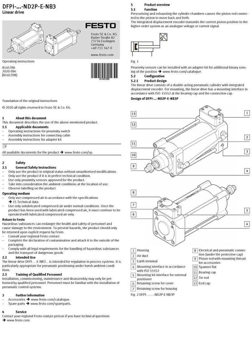
  9. Festo DFPI ND2P-E-NB3P Series User manual

Festo DFPI ND2P-E-NB3P Series User manual

Linear drive
DFPI-...-ND2P-E-NB3P
Festo AG & Co. KG
Ruiter Straße 82
73734 Esslingen
Germany
+49 711 347-0
www.festo.com
Translation of the original instructions 8076535
2017-12b
[8076537]
Linear drive DFPI-...-ND2P-E-NB3P English...............................
For all available product documentation èwww.festo.com/pk
1 Design
1
2
3
aA
aB
8
4
aJ
9
5
6
7
4
1Housing
2Air duct
3Earth terminal
4Mounting interface in accordance
with ISO 15552
5Mounting kit interface for external
positioner
6Housing mounting screw
7Electrical and pneumatic
connection (under the protective
cap)
8Piston rod with mounting thread
for accessories
9Spanner flat
aJ Bearing cap
aA Tie rod
aB End cap
Fig. 1
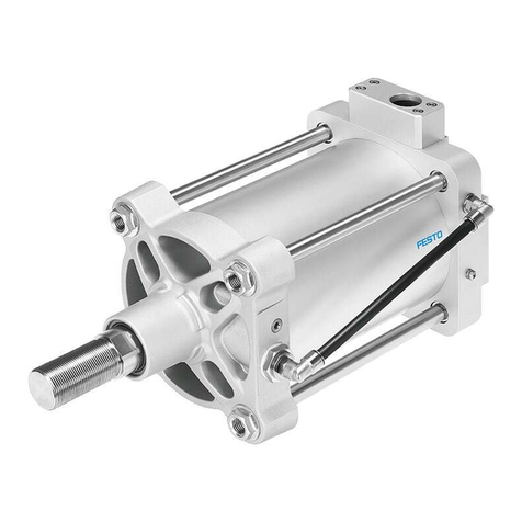
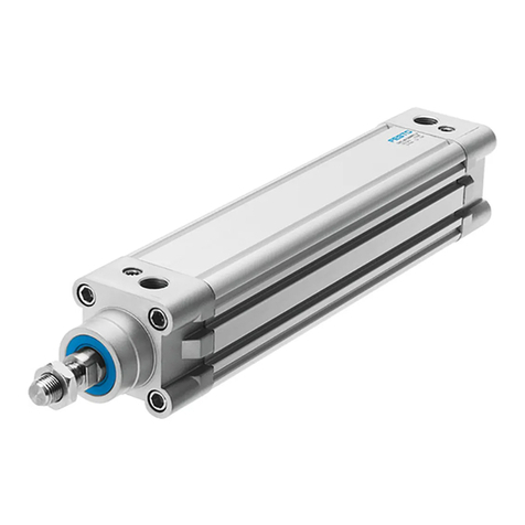
The DFPI-...-ND2P-E-NB3P linear drive consists of a double-acting pneumatic cylin
der with integrated displacement encoder.
The electrical and pneumatic connections are protected from outside mechanical
influences by a sturdy housing. A pre-assembled connecting cable with protective
conduit is available as an accessory.
For mounting, the DFPI-...-ND2P-E-NB3P has a mounting interface in accordance
with ISO15552 at the bearing cap and the connection cap.
A aide range of accessories is available for the product
(èwww.festo.com/catalogue).
Product variants and type code
Characteristic Value Description
Type DFPI Regulated drive for process automation
Piston diameter 100, 125, 160,
200, 250, 320
Piston diameter can be selected in steps;
specifications in [mm]
Stroke x x = Length [40 to 990 mm]
Cushioning N No cushioning
Displacement encoder D2 Analogue
Method of measurement P Potentiometer
Attachment position of
controller
EExternal (no controller integrated)
Standard NB3 Based on ISO 15552
Connection type PProtected pneumatic connections
Fig. 2
2 Safety
Intended use
The DFPI-...-ND2P-E-NB3P linear drive is intended for regulation in process en
gineering systems. It is particularly appropriate for pneumatic positioning under
rough operating conditions.
– The product may only be used in its original status without unauthorised
modifications.
– Only use the product if it is in an excellent technical status.
– Use only proximity sensors approved for the product.
– Take into consideration the operating conditions at the location of use.
– Observe the specifications on the product labelling.
– Comply with all applicable national and international regulations.
Operating medium
– Use only compressed air in accordance with the specifications (èTechnical
data).
– Use only unlubricated compressed air under normal conditions. Once the pro
duct has been used with lubricated compressed air, it must continue to be ope
rated with compressed air only.
Drive
Impermissible lateral forces on the piston rod can damage the piston rod bearing.
– Do not exceed the maximum permissible lateral forces on the piston rod
(èFig. 10).
– Guide the piston rod, if necessary, to avoid start-up oscillations.
Return to Festo
Hazardous substances can endanger the health and safety of personnel and cause
damage to the environment. To prevent hazards, the product should only be retur
ned upon explicit request by Festo.
– Consult your regional Festo contact.
– Complete the declaration of contamination and attach it to the outside of the
packaging.
– Comply with all of the legal requirements for the handling of hazardous
substances and the transport of dangerous goods.
3 Function
Pressurising and venting of the cylinder
chambers cause the piston rod connected
to the piston to move to and fro.
The integrated displacement encoder
transmits the current piston position to the
higher-level system as an analogue voltage
signal.
Fig. 3
Proximity sensors can be installed by means of an adapter kit for additional binary
sensing of positions (Accessories èwww.festo.com/catalogue).
4 Transport and storage
Warning
Danger of crushing! Danger of shearing!
The product without accessories weighs up to about 56 kg, depending on the
product version.
Body parts can be crushed or severed if the product falls.
 Use appropriate load handling equipment.
 Do not use the air duct as a handle for carrying.
 When shipping used products: Comply with all legal requirements for handling
hazardous substances and transporting dangerous goods.
For return to Festo èChapter 2.
 Remove all attachments.
 Store the product in a cool, dry, UV- and corrosion-protected environment.
Ensure storage times are short.
5 Installation
Note
Installation should only be conducted by qualified specialized personnel.
5.1 Mechanical installation
It can be mounted in any position.
1. Remove all transport packaging. The material used in the packaging has been
specifically chosen for its recyclability (exception: oil-impregnated paper =
residual waste).
2. Fasten the drive with the mounting screws on the bearing cap/end cap
(mounting interface in accordance with ISO 15552). Tighten the mounting
screws evenly.
– Tightening torques èFig. 4.
Piston diameter Tightening torque [Nm]
100 10
125 24
160 70
200 70
250 150
320 250
Fig. 4
When using additional proximity sensors
Note
When linear drives are installed too close to each other, the cylinder magnet can
disturb the proximity sensor on the adjacent linear drive.
1. Fasten sensor bracket to the tie rod.
– Tightening torque 0.6 … 1 Nm.
2. Mount proximity sensor (èProximity sensor operating instructions).
3. Check minimum distances to ferritic and magnetic materials. Place the drive so
that trouble-free operation is possible.
4. Fasten the drive.
When mounting accessory parts on the piston rod
1. Attach accessory parts to the male thread of the piston rod (Fig. 1, 8).
2. Tighten nut and accessories.
5.2 Electrical installation
Warning
Use for the electrical power supply only PELV circuits in accordance with
IEC/EN 60204-1. Use only power sources which guarantee reliable electrical
isolation of the operating voltage in accordance with IEC/EN 60204-1.
1Mounting screws
2Seal (O-ring)
3Opening for electrical and
pneumatic connection
4Mounting thread (M32 x 1.5) for
connecting cable (accessories)
Fig. 5
1
2
4
3
Pin Assignment Plug connector
10 V 31 2
2Sensor signal (actual value) 0 … 15 V DC
3Operating voltage 15 V DC
Fig. 6
1. Select appropriate electrical connecting cable.
– At least 3-wire with wire end sleeves, outside diameter 6.5 … 8 mm.
– Conductor cross-section: 0.75 … 1.5 mm²
Note
Recommendation: Use the NHSB connecting cable with protective conduit
(èwww.festo.com/catalogue). Installation èConnecting cable mounting in
structions.
2. Loosen the mounting screws ( Fig. 5, 1) and carefully remove the housing.
3. If present, loosen the cable connector of the connecting cable.
4. Disconnect the pre-assembled plug at the electrical connection (2 screws)
5. Guide the electrical connecting cable through the passage in the housing
(Fig. 5,3) and wire it to the plug (èFig. 6).
6. Fasten the wired plug to the electrical connection.
– 2 screws, tightening torque 0.5 Nm ±10 %.
7. Mount the housing onto the drive. Make sure that the seal (O-ring) is seated
correctly.
– Tightening torque of the mounting screws: 2.7 Nm ±10 %.
8. Connect the earth terminal (Fig. 1, 3) to the earth potential with low
impedance (short cable with large cross-section).
5.3 Pneumatic installation
2
1
4
3
1Pneumatic connection: Retract
piston rod
2Pneumatic connection: Extend
piston rod
3Connecting cable
4Housing
Fig. 7
1. Prepare pneumatic connection.
– Check the necessity of non-return valves. They prevent the moveable mass
from sliding down if there is a drop in pressure when the product is in a
vertical or sloping mounting position.
– Use outside-calibrated pneumatic lines with outside diameter of 8 mm
(e.g. plastic tubing PUN-8x1,25 from Festo).
– Cut tubing ends at right angles and without burrs. This avoids damage to
internal O-rings.
2. Connect the linear drive to the compressed air supply ports with hoses
(èFig. 7).
– Pay attention to the desired direction of movement of the piston rod.
– Plug the hose into the push-in fitting up to the stop.
– Check that the hose is securely held by pulling gently on it
6 Commissioning
Note
Commissioning should only be conducted by qualified personnel.
Requirements
– The drive is fully mounted and connected.
Commissioning the drive
1. Check operating conditions and limit values (èTechnical data).
2. Provide power supply (Operating medium, Operating voltage).
3. Check correct function at first with a low travel speed.
7 Operation
Warning
Danger of crushing! Danger of shearing!
The piston rod moves fast and with great force. Body parts in the movement
range of the piston can be crushed or severed.
 Do not reach into the movement range of the piston rod.
 Do not place foreign objects in the movement range of the piston rod.
 Observe the operating conditions.
 Observe permitted limit values.
8 Maintenance and care
If used as intended, the product is maintenance-free.
9 Disassembly
Note
Disassembly only by qualified specialized personnel.
1. Disconnect the drive from the power supply (operating medium, electric power).
2. Loosen the mounting screws ( Fig. 5, 1) and carefully remove the housing.
3. Disconnect electrical and pneumatic connection.
4. Loosen the mounting screws and remove the drive.
Loosening a hose
1. Press down on the disconnect ring (blue) of the push-in fitting and hold it down.
2. Carefully pull the tube out of the push-in fitting.
Cut off the damaged part before using the hose further.
10 Disposal
 Observe the local specifications for environmentally friendly disposal.
 Dispose of the product in an environmentally friendly manner. When doing this,
also take residual media into account (potential recycling of hazardous waste).
11 Fault clearance
Malfunction Possible cause Remedy
Piston rod does
not move in the
desired direction
Displacement encoder cable incorrectly connected
at positioning controller or DFPI
(e.g. connections at pin 1 and pin 3 interchanged).
Correct the connection
Supply ports connected incorrectly Correct the connection
Fig. 8
12 Technical data
DFPI-… -100 -125 -160 -200 -250 -320
Type of mounting Mounting interface in accordance with ISO 15552
Spanner size of the piston rod 22 27 36 36 46 55
Stroke [mm] 40 … 990
Min./max. stroke allowance [mm] 0 … 4
Design Piston rod, cylinder barrel
Cushioning No cushioning
Mounting position Any
Mode of operation Double-acting
Position sensing Via integrated displacement encoder
Measuring principle of displacement enco
der
Potentiometer
Operating voltage range [V DC] 0 … 15
Independent linearity [%
FS]
±0.04
Hysteresis [mm] 0.33
Repetition accuracy [mm] ±0.12
Resistance value of displacement encoder (on the T.E.P.) dependent on the stroke length 1)
–š290 mm [kΩ] 5
–,290 mm to 590 mm [kΩ] 10
–,590 mm to 990 mm [kΩ] 20
Recommended current at the displacement encoder
– Recommended contact current [ìA]  0.1
– Max. short-time contact current [mA] 10
Electrical connection 3-pin; straight plug; screw terminal
Pneumatic connection For tubing outside 8 mm
Operating pressure [bar] 3 … 8
Nominal operating pressure [bar] 6
DFPI-… -100 -125 -160 -200 -250 -320
Operating medium Compressed air in accordance with ISO 8573-1:2010
[7:4:4]
Note on the operating medium Lubricated operation possible (in which case lubric
ated operation will always be required)
Protection class - in mounted status IP65, IP67, IP69K, NEMA 4
Ambient temperature [°C] –20 … +80
Corrosion resistance class CRC 3
Product weight
– Basic weight with 0 mm stroke [g] 4900 7500 12800 18100 31100 57700
– Additional weight per 10 mm
stroke
[g] 90 134 200 238 358 582
– Moving mass with 0 mm stroke [g] 1060 1900 3700 4800 9300 16500
– Additional weight of moving
load per 10 mm stroke
[g] 28 53 89 89 134 227
Information on materials
– Cylinder barrel Anodised wrought aluminium alloy
– Cap (end cap) Wrought aluminium alloy, coated
– Bottom cap (bearing cap) Coated die-cast aluminium
– Tie rods High-alloy stainless steel
– Piston rod High-alloy stainless steel
– Flange screws/nuts Coated steel
– Piston rod seal PUR NBR
– Static seal NBR
Note on materials PWIS-free, RoHS-compliant
Vibration resistance in accordance with
DIN/IEC 68, Part 2-6
0.35 mm travel at 0 … 60 Hz;
5 g acceleration at 0 … 150 Hz
Continuous shock resistance in accordance
with DIN/IEC 68, Part 2-82
±15 g at 6 ms duration;
1000 shocks per direction
1) T.E.P. = theoretical electrical path
Fig. 9
Max. permissible lateral force for static application
Note
In controlled operation, adjustment of the max. lateral force to the type of con
trol may be required.
Horizontal installation
Vertical installation
Ø 100
Ø 125
Ø 160/200
Ø 250
Ø 320
Fig. 10
Other Festo DC Drive manuals

Festo EMCS ST Series Reference guide

Festo

Festo EMCS ST Series Reference guide

Festo TP 1422 Operation instructions

Festo

Festo TP 1422 Operation instructions

Festo DFPI ND2P-E-NB3 Series User manual

Festo

Festo DFPI ND2P-E-NB3 Series User manual

Festo DGCI Series User manual

Festo

Festo DGCI Series User manual

Festo FDG-...-ZR-RF Series User manual

Festo

Festo FDG-...-ZR-RF Series User manual

Festo EMCA-EC-67 CO Series Reference guide

Festo

Festo EMCA-EC-67 CO Series Reference guide

Festo DGC-HD Series Parts list manual

Festo

Festo DGC-HD Series Parts list manual

Festo DFPI Series User manual

Festo

Festo DFPI Series User manual

Festo DFPD-Series User manual

Festo

Festo DFPD-Series User manual

Festo DFPD-Series User manual

Festo

Festo DFPD-Series User manual

Festo ERMO Series User manual

Festo

Festo ERMO Series User manual

Festo DGC-8 Series User manual

Festo

Festo DGC-8 Series User manual

Festo DGC-K Series Setup guide

Festo

Festo DGC-K Series Setup guide

Festo EMCA-EC-67 CO Series Reference guide

Festo

Festo EMCA-EC-67 CO Series Reference guide

Festo ERMO User manual

Festo

Festo ERMO User manual

Festo DDLI-25 User manual

Festo

Festo DDLI-25 User manual

Festo ELCC-TB-KF Parts list manual

Festo

Festo ELCC-TB-KF Parts list manual

Festo DGO-xxx-A-B series User manual

Festo

Festo DGO-xxx-A-B series User manual

Festo DGC 1H-PN Series User manual

Festo

Festo DGC 1H-PN Series User manual

Festo EMCA-EC-67 CO Series User manual

Festo

Festo EMCA-EC-67 CO Series User manual

Festo DFPD-HD-RD Series Parts list manual

Festo

Festo DFPD-HD-RD Series Parts list manual

Festo DFPD-Series User manual

Festo

Festo DFPD-Series User manual

Festo CMMT-AS-C2-11A-P3 S1 Series User manual

Festo

Festo CMMT-AS-C2-11A-P3 S1 Series User manual

Festo DGC-HD Series User manual

Festo

Festo DGC-HD Series User manual

Popular DC Drive manuals by other brands

Nord Drivesystems SK 200E Series manual

Nord Drivesystems

Nord Drivesystems SK 200E Series manual

Danfoss 73691290 operating guide

Danfoss

Danfoss 73691290 operating guide

Lenze E84AVHCE HighLine C Series Mounting instructions

Lenze

Lenze E84AVHCE HighLine C Series Mounting instructions

Automationdirect.com IRONHORSE GSD1 Series user manual

Automationdirect.com

Automationdirect.com IRONHORSE GSD1 Series user manual

BONFIGLIOLI Act 201 quick start guide

BONFIGLIOLI

BONFIGLIOLI Act 201 quick start guide

Siemens COMBIMASTER 411 operating instructions

Siemens

Siemens COMBIMASTER 411 operating instructions

ABB ACS880+N5350 user guide

ABB

ABB ACS880+N5350 user guide

Parker AC70 product manual

Parker

Parker AC70 product manual

Lenze L-force 8400 Series Mounting instructions

Lenze

Lenze L-force 8400 Series Mounting instructions

REDEX ANDANTEX Z Series Setup and maintenance instructions

REDEX ANDANTEX

REDEX ANDANTEX Z Series Setup and maintenance instructions

ESBE ALF 1 Series manual

ESBE

ESBE ALF 1 Series manual

MegaLite DECO Series user manual

MegaLite

MegaLite DECO Series user manual

Delta CP2000 Series user manual

Delta

Delta CP2000 Series user manual

Phase Technologies SD Series troubleshooting guide

Phase Technologies

Phase Technologies SD Series troubleshooting guide

SecureData SecureDrive BT quick start guide

SecureData

SecureData SecureDrive BT quick start guide

KEBCO COMBIVERT F5 instruction manual

KEBCO

KEBCO COMBIVERT F5 instruction manual

XPPen XP-Pen user manual

XPPen

XPPen XP-Pen user manual

Yolico YD3000N Series instruction manual

Yolico

Yolico YD3000N Series instruction manual

manuals.online logo
manuals.online logoBrands
  • About & Mission
  • Contact us
  • Privacy Policy
  • Terms and Conditions

Copyright 2025 Manuals.Online. All Rights Reserved.