manuals.online logo
Brands
  1. Home
  2. •
  3. Brands
  4. •
  5. Festo
  6. •
  7. Engine
  8. •
  9. Festo EMMT-AS Series User manual

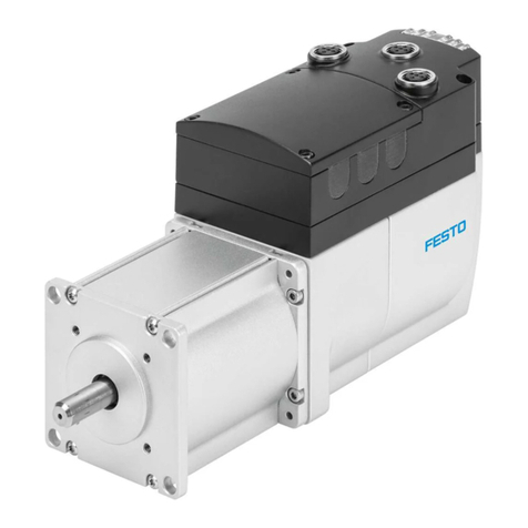
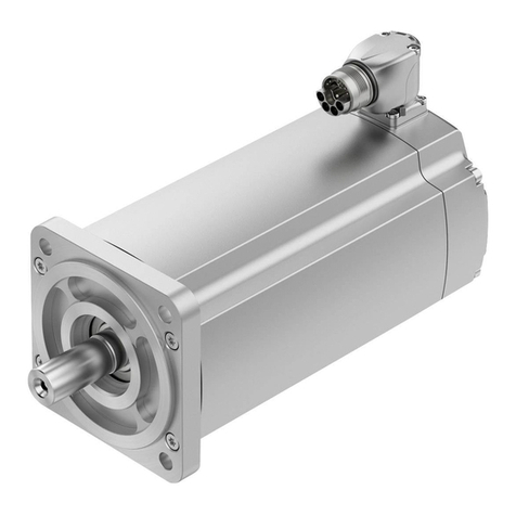
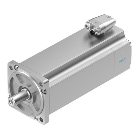
Festo EMMT-AS Series User manual

EMMT-AS
Servo motor
Festo SE & Co. KG
Ruiter Straße 82
73734 Esslingen
Deutschland
+49 711 347-0
www.festo.com
Operating instructions
8176711
2022-04d
[8176713]
Translation of the original instructions
© 2022 all rights reserved to Festo SE & Co. KG
EnDat® is a registered trademark of its respective trademark holder in certain
countries.
1About this document
1.1 Applicable documents
All available documents for the product è www.festo.com/sp.
Document Product Contents
Addendum document | Safety
manual
Safety absolute encoder EMMT-
AS-...-MY
Multi-turn, EnDat 2.2
Tab. 1: Applicable documents for the product
1.2 Product version
This documentation describes the following product versions:
EMMT-AS-...-K/-R-...-R/-R2/-R3/-
S/-M/-B
Product version
-K with featherkey
-R with rotary shaft seal
-R EMMT-AS-60/80/100: angled plug, can be aligned
-R2 EMMT-AS-150: M23 angled plug, can be aligned
-R3 EMMT-AS-190: M40 angled plug, can be aligned
-S Absolute encoder, single-turn
-M Absolute encoder, multi-turn
-B with holding brake
Tab. 2: Product version
1.3 Product labelling
Additional information è www.festo.com/catalogue.
Control ele-
ment
Description
Motor EMMT-AS-...
UZK [V] Nominal operating voltage DC
INph [A] Nominal current
Imax [A] Peak current
I0[A] Continuous stall current
PN[kW] Nominal power
ke[mVmin] Voltage constant
MN[Nm] Nominal torque
M0[Nm] Stall torque
nN[rpm] Nominal rotational speed
nmax [rpm] Maximum mechanically permissible rotational speed
n0max [rpm] Maximum idling speed
Class 155 (F) Temperature class F (155°C)
Holding brake EMMT-AS-...-B
UB[V] Operating voltage DC
Operating and environmental conditions
IPxx Degree of protection1)
è www.festo.com/sp approval
CE mark for the European Union.2)3)
UL certification mark for the USA and Canada.
Control ele-
ment
Description
RCM certification mark for Australia and New Zealand.
UKCA certification mark for Great Britain
1) A rotary shaft seal on the motor is required for vertical operation subject to dripping water.
2) Declaration of conformity: all data in accordance with IEC 60034.
3) EMC Directive: the product is intended for use in industrial environments. Measures for interference
suppression may be required in residential areas. The product may generate high frequency interference,
which may require interference suppression measures in residential areas. Additional measures are
required to comply with the EMC Directive for cables > 30 m. Compliance with the EMC Directive is
the responsibility of the user.
Tab. 3: Identifiers on the product labelling
2 Safety
2.1 Safety instructions
–Observe labelling on the product.
–Before working on the product, switch off the power supply and secure it
against being switched on again.
–Store the product in a cool, dry environment protected from UV and corrosion.
Keep storage times short.
–Store the product in ambient conditions without oils, greases and grease-dis-
solving vapours.
2.2 Intended use
The motor is intended to be used as a component in drive systems in accordance
with EN 61800 and may only be operated in combination with a suitable servo
drive.
2.3 Foreseeable misuse
The holding brake must not be used for braking the motor.
2.4 Training of qualified personnel
Work on the product may only be carried out by qualified personnel who can
evaluate the work and detect dangers.
The qualified personnel must be familiar with the assembly and installation of
electric drive systems.
2.5 Area of application and approval
Validity of the UL approval
The UL approval is only valid for the EMMT-AS-60/-80/-100-... servo motors.
In combination with the UL inspection mark on the product, the information in this
section must also be observed in order to comply with the certification conditions
of Underwriters Laboratories Inc. (UL) for USA and Canada.
UL certification information
Product category code PRHZ2 (USA) or PRHZ8 (Canada)
File number E342973
Considered standards UL 1004-1/-6, C22.2 No.100
UL mark
Tab. 4: UL/CSA certification information
3 Additional information
–Contact the regional Festo contact if you have technical problems
è www.festo.com.
–Accessories è www.festo.com/catalogue.
4 Product overview
4.1 Function
The product is a permanently excited, electrodynamic, brushless servo motor. The
integrated absolute encoder serves to record the angular position and derives the
angular velocity signals and other status variables. These signals are evaluated
by a higher-order servo drive. The de-energised holding brake enables the motor
shaft to be held at a standstill.
4.2 Product design
1 2 3 4 5 6
7891011
Fig. 1: Product design EMMT-AS,
example EMMT-AS-150-...
1
Electrical connection: motor, holding
brake, absolute encoder
2
Threaded hole for lifting eye bolt
3
Through-hole for mounting
4
Motor flange
5
Featherkey
6
Motor shaft
7
Rotary shaft seal
8
Product labelling
9
Warning: dangerous electrical voltage
10
Warning: hot surface
11
Note: mechanical impacts not per-
mitted
5 Transport
WARNING
Risk of injury due to falling product
If the product is lifted incorrectly, it may fall and cut, crush or separate body parts.
• Lift the product only with suitable load-bearing equipment.
–Store and transport the product in its original packaging. Observe the weight,
the dimensions and the ambient conditions.
–Store and transport the product in a horizontal position.
6 Assembly
WARNING
Risk of injury due to unexpected movement of components.
• Bring moving parts of the connected mechanical system into a secure position
(e.g. move into the lower end position).
WARNING
Risk of injury due to falling product
If the product is lifted incorrectly, it may fall and cut, crush or separate body parts.
• Lift the product only with suitable load-bearing equipment.
•Product weight ≥25 kg: use only lifting eye bolts as lifting aids.
• Do not use the electrical connection and the motor shaft as a lifting aid.
Axial and radial forces on the motor shaft.
Excessive axial and radial forces on the motor shaft can damage the motor.
• Comply with maximum permissible shaft loads è www.festo.com/catalogue.
6.1 Unpacking product
1. Open packaging.
2. Remove all transport materials, e.g. foils, caps, cardboard boxes.
3. For product weight ³ 25 kg: mount two lifting eye bolts as lifting aid.
4. Remove the product from the packaging and place it on the mounting surface.
5. Dispose of packaging and transport materials.
6.2 Mounting motor
Requirement
–Select accessories è www.festo.com/catalogue.
1. Degrease and dry the motor shaft.
2. Mount motor on the driven mechanical system.
Instruction manual for drive unit, gear unit and mounting kit
è www.festo.com/sp.
7 Installation
WARNING
Risk of injury due to electric shock.
• Switch off power supply prior to assembly and installation work; ensure that it
is off and secure it against being switched back on.
Cancelling the enable signal is not sufficient.
WARNING
Risk of injury due to electric shock.
High voltage potential can injure people when the motor plug is disconnected.
• Use appropriate measures to ensure that the motor plug cannot be discon-
nected.
WARNING
Risk of injury from electric shock.
Inadequate earthing of the product may result in dangerous leakage current when
touching the motor housing, which can cause serious injuries.
•Additional earthing on the machine bed is required for cable lengths ³ 50 m.
7.1 Connecting cable and earthing
Motor earthing
Earthing close to the motor with electrical continuity to the motor flange is
required on the machine bed for cable lengths ³ 50 m.
Motor connection
Fig. 2: Connect and align motor cable
Requirement
–Select accessories è www.festo.com/catalogue.
–Observe permissible cable length and conductor cross section
è www.festo.com/catalogue.
–Use screened cables.
1. Connect cable (A) to the plug and tighten the screw-type lock (B).
2. Align plug (C) (can be swivelled 310°).
3. Connect the cable to the servo drive.
Instructions for servo drive and cable è www.festo.com/sp.
Plug, M23/M40, 15-pin,
pins
Pin Function Description
Servo motor EMMT-AS-...
M23
M40
A U Motor phase U
B V Motor phase V
C W Motor phase W
D – not connected
PU PU Protective earthing
Holding brake EMMT-AS-...-...B
1 BR– Reference potential 0 V
2 – not connected
3 – not connected
4 BR+ Holding brake control:
–24 V DC (21.6 … 25.44 V DC): open
(released)
–0 V DC: closed (tripped)
EnDat 2.2 absolute encoder, single-turn/multi-turn
EMMT-AS-...-...S/M
5 USSupply voltage 3.6...14 V DC
6 GND Earth 0 V
7 DATA Data cable, bidirectional, RS485-compliant,
differential
8 #DATA
9 CLOCK Clock line, input, RS485-compliant, differ-
ential
10 #CLOCK
Tab. 5: Plug for motor, holding brake and absolute encoder
8Commissioning
WARNING
Risk of injury due to unexpected movement of components.
• When releasing the holding brake, secure the driven mechanical system to
prevent unintended movement.
•Deenergise the motor before releasing the holding brake manually.
• Before setting the enable signal, protect the traversing range of the driven
mechanical system from access.
Voltage loss at the holding brake
High voltage loss in the motor cable can result in the permissible operating
voltage of the holding brake being undershot.
8.1 Commissioning procedure
Before operating the motor with a servo drive, the electrical safety and EMC
must be checked for this device combination in accordance with the Low Voltage
Directive and the EMC Directive. In particular, the drive system may only be
commissioned if conformity has been confirmed in accordance with EN 61800.
1. Commission the motor in combination with a suitable servo drive.
Instructions for servo drive è www.festo.com/sp.
2. Check function and holding torque of the holding brake.
For the grinding-in process of the brake system, briefly close the holding
brake at low rotational speed, e.g. 3 s at 100 rpm.
9Operation
WARNING
Risk of injury due to unexpected movement of components.
Body parts in the movement range of the piston rod can be crushed or severed.
• Protect the positioning range from unwanted intervention.
•Keep foreign objects out of the positioning range.
WARNING
Danger of burns from hot housing surfaces.
Metallic housing parts can reach high temperatures during operation.
Contact with metal housing parts can cause burn injuries.
•Do not touch metallic housing parts.
• After the power supply is switched off, let the device cool down to room
temperature.
Axial and radial forces on the motor shaft.
Excessive axial and radial forces on the motor shaft can damage the motor.
• Comply with maximum permissible shaft loads è www.festo.com/catalogue.
• Check the function and holding torque of the holding brake at regular inter-
vals.
If the holding torque is reduced, close the holding brake briefly at low speed,
e.g. 3 s at 100 rpm.
10 Maintenance
WARNING
Risk of injury due to electric shock.
• Switch off power supply prior to assembly and installation work; ensure that it
is off and secure it against being switched back on.
Cancelling the enable signal is not sufficient.
WARNING
Risk of injury due to unexpected movement of components.
• Bring moving parts of the connected mechanical system into a secure position
(e.g. for vertical installation, move the slide into the lower end position).
•Only then should you disconnect the motor from the mechanical system.
WARNING
Danger of burns from hot housing surfaces.
Metallic housing parts can reach high temperatures during operation.
Contact with metal housing parts can cause burn injuries.
•Do not touch metallic housing parts.
• After the power supply is switched off, let the device cool down to room
temperature.
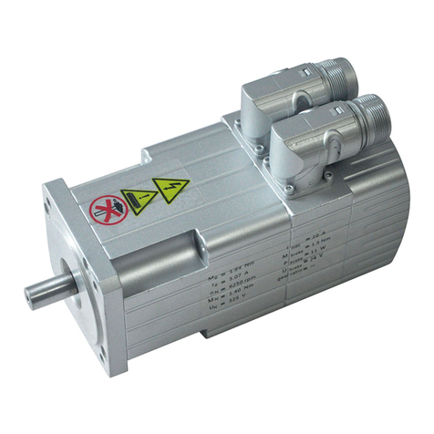
10.1 Replace the rotary shaft seal
For variants with rotary shaft seal EMMT-AS-...-...R-...:
•Rotary shaft seal EASS must be replaced after 5,000 operating hours at the
latest è Instructions for rotary shaft seal, è www.festo.com/sp.
10.2 Cleaning
Before cleaning, the product must be cooled down to below 40°C.
Clean the outside of the product with a soft cloth as required. Cleaning agents
include all non-abrasive media.
11 Malfunctions
WARNING
Risk of injury due to electric shock.
• Switch off power supply prior to assembly and installation work; ensure that it
is off and secure it against being switched back on.
Cancelling the enable signal is not sufficient.
WARNING
Risk of injury due to unexpected movement of components.
• Bring moving parts of the connected mechanical system into a secure position
(e.g. for vertical installation, move the slide into the lower end position).
•Only then should you disconnect the motor from the mechanical system.
WARNING
Danger of burns from hot housing surfaces.
Metallic housing parts can reach high temperatures during operation.
Contact with metal housing parts can cause burn injuries.
•Do not touch metallic housing parts.
• After the power supply is switched off, let the device cool down to room
temperature.
11.1 Fault clearance
Servo motor and absolute encoder
• Motor must not be opened.
• Repairs may only be carried out by the Festo repair service.
Malfunction Possible cause Remedy
Loud rotation noises of
the motor shaft.
Coupling distance too
short.
Observe permissible coupling distances
è Instruction manual for motor mounting kit,
è www.festo.com/sp.
Motor shaft does not
turn.
Excessive load. Reduce load.
Servo drive has not yet
been enabled.
Check signals.
Holding brake closed. Release holding brake.
Min. operating voltage
for opening the
holding brake is not
reached.
–Comply with permissible cable length and
cable cross section è www.festo.com/cata-
logue.
–Contact local Festo Service.
Malfunction Possible cause Remedy
Torque of the motor
shaft is not transmitted
to the drive system.
Coupling slips. Check the mounting of the shaft-hub connection
è Instruction manual for the motor mounting
kit, è www.festo.com/sp.
Motor shaft vibrates. Current controller set-
tings.
Optimise controller data, e.g. velocity, accelera-
tion, ...
Motor shaft rotates in
the wrong direction.
Wiring fault. Check and correct wiring.
Holding torque of the
holding brake is not
reached.
Insufficient condi-
tioning of the brake
disc.
Briefly close the holding brake several times at
low speed, e.g. 3 s at 100 rpm.
Holding torque of the
holding brake not
effective.
Holding brake fault,
e.g. excessive axial
force on the motor
shaft.
–Replace motor è www.festo.com/catalogue.
–Observe max. permissible axial force,
e.g. mount the coupling so it is free of ten-
sion.
Encoder signals not
transmitted.
Wiring fault. Check and correct wiring.
Encoder fault,
e.g. excessive axial
force on the motor
shaft.
–Replace motor è www.festo.com/catalogue.
–Observe max. permissible axial force,
e.g. mount the coupling so it is free of ten-
sion.
Tab. 6: Overview of fault clearance
12 Demounting
WARNING
Risk of injury due to falling product
If the product is lifted incorrectly, it may fall and cut, crush or separate body parts.
• Lift the product only with suitable load-bearing equipment.
•Product weight ≥25 kg: use only lifting eye bolts as lifting aids.
• Do not use the electrical connection and the motor shaft as a lifting aid.
1. Disconnect electrical installations.
2. Remove motor.
3. Observe transport information è 5 Transport.

Other Festo Engine manuals

Festo DSBG Series Setup guide

Festo

Festo DSBG Series Setup guide

Festo MTR series User manual

Festo

Festo MTR series User manual

Festo EMME-AS-100-S Series User manual

Festo

Festo EMME-AS-100-S Series User manual

Festo MTR-DCI series Reference guide

Festo

Festo MTR-DCI series Reference guide

Festo MTR-DCI series User manual

Festo

Festo MTR-DCI series User manual

Festo MTR-DCI Reference guide

Festo

Festo MTR-DCI Reference guide

Festo EMMS-ST-57-S Series User manual

Festo

Festo EMMS-ST-57-S Series User manual

Festo MTR-DCI-...IO Series Operating and installation instructions

Festo

Festo MTR-DCI-...IO Series Operating and installation instructions

Festo EMMS-ST-28-L Series User manual

Festo

Festo EMMS-ST-28-L Series User manual

Festo EMMT-AS Series User manual

Festo

Festo EMMT-AS Series User manual

Festo MTRE-ST42-48S Series User manual

Festo

Festo MTRE-ST42-48S Series User manual

Festo EMMT-AS Series Parts list manual

Festo

Festo EMMT-AS Series Parts list manual

Festo EMMT-AS Series User manual

Festo

Festo EMMT-AS Series User manual

Festo ADVU Series Setup guide

Festo

Festo ADVU Series Setup guide

Festo MTR series User manual

Festo

Festo MTR series User manual

Festo EMMB-AS User manual

Festo

Festo EMMB-AS User manual

Festo EMCA-EC-67 CO Series User manual

Festo

Festo EMCA-EC-67 CO Series User manual

Festo EMME-AS Series User manual

Festo

Festo EMME-AS Series User manual

Festo MTR-DCI series Reference guide

Festo

Festo MTR-DCI series Reference guide

Festo MTR-DCI series Reference guide

Festo

Festo MTR-DCI series Reference guide

Festo EMMS-AS-100-M-RS User manual

Festo

Festo EMMS-AS-100-M-RS User manual

Festo EMMS-ST-28-L Series User manual

Festo

Festo EMMS-ST-28-L Series User manual

Festo MTR series User manual

Festo

Festo MTR series User manual

Festo MTR-DCI-x-PB Series User manual

Festo

Festo MTR-DCI-x-PB Series User manual

Popular Engine manuals by other brands

norbar PneuTorque PTS-52-500 Operator's manual

norbar

norbar PneuTorque PTS-52-500 Operator's manual

Audi V8 Service

Audi

Audi V8 Service

LinMot PR02-70 Series installation guide

LinMot

LinMot PR02-70 Series installation guide

ABB ESM Series quick guide

ABB

ABB ESM Series quick guide

Volvo Penta D13 Series Operator's manual

Volvo Penta

Volvo Penta D13 Series Operator's manual

PEUGEOT XS1P52QMI-4 Workshop manual

PEUGEOT

PEUGEOT XS1P52QMI-4 Workshop manual

Weston WEST EUROTECH 50 V1 instructions

Weston

Weston WEST EUROTECH 50 V1 instructions

Louvolite R1905 operating instructions

Louvolite

Louvolite R1905 operating instructions

panthera PM07-18 owner's manual

panthera

panthera PM07-18 owner's manual

Chery SQR372 Maintenance manual

Chery

Chery SQR372 Maintenance manual

Westerbeke 65A-FOUR Operator's manual

Westerbeke

Westerbeke 65A-FOUR Operator's manual

Suzuki F6A Service manual

Suzuki

Suzuki F6A Service manual

Subaru EX13 Service manual

Subaru

Subaru EX13 Service manual

O.S. engine MAX-25AX & MAX-35AX instruction manual

O.S. engine

O.S. engine MAX-25AX & MAX-35AX instruction manual

Wacker Neuson WM 130 Repair manual

Wacker Neuson

Wacker Neuson WM 130 Repair manual

Lenze g500-B Project planning manual

Lenze

Lenze g500-B Project planning manual

Yamaha XF375 owner's manual

Yamaha

Yamaha XF375 owner's manual

ABB MT series Installation, operation & maintenance manual

ABB

ABB MT series Installation, operation & maintenance manual

manuals.online logo
manuals.online logoBrands
  • About & Mission
  • Contact us
  • Privacy Policy
  • Terms and Conditions

Copyright 2025 Manuals.Online. All Rights Reserved.