Translation of the original instructions
1 About this document
This document describes the use of the above-mentioned product. For detailed
specifications on the product, a complete description, the software for the device
(IODD) and the declaration of conformity èwww.festo.com.
1.1 Further applicable documents
All available documents for the product èwww.festo.com/pk.
2 Safety
2.1 Intended use
The position transmitter SDAS-MHS is intended for monitoring the piston stroke.
Only use the position transmitter for suitable drives from Festo
èwww.festo.com/catalogue. Avoid positioning magnetic objects in close prox-
imity to the position transmitter.
2.2 General safety instructions
– Only use the product in original status without unauthorised modifications.
– Only use the product if it is in perfect technical condition.
– Take into consideration the ambient conditions at the location of use.
– Observe limit values .
Return to Festo
– Consult your regional Festo contact.
2.3 Area of application and approval
NOTICE!
CE declaration of conformity èwww.festo.com/sp.
2.4 Training of skilled personnel
Installation, commissioning, maintenance and disassembly should only be con-
ducted by qualified personnel.
3 Service
Contact your regional Festo contact person if you have technical questions
èwww.festo.com.
4 Product overview
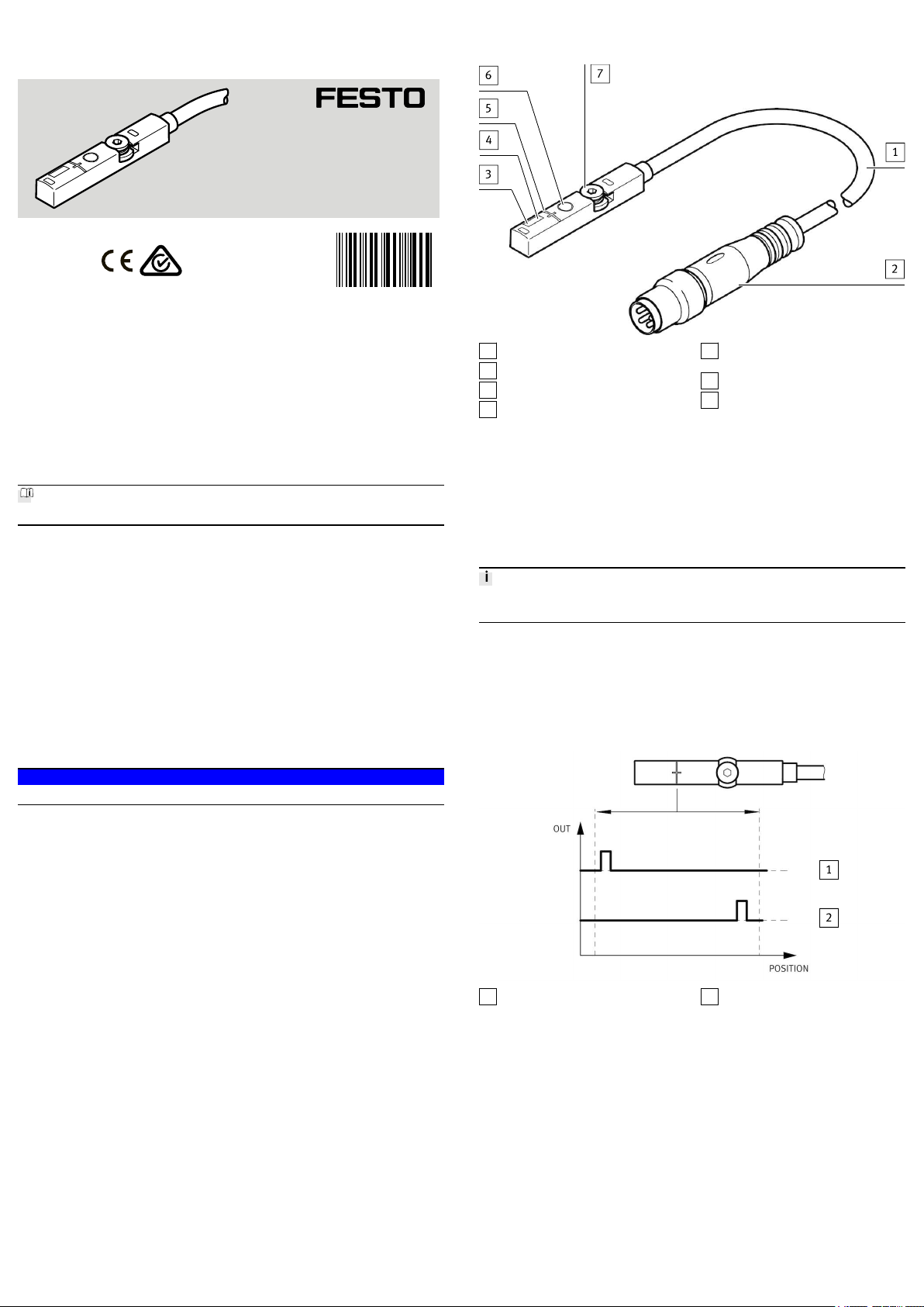
4.1 Design
1Connecting cable
2M8 plug, rotatable
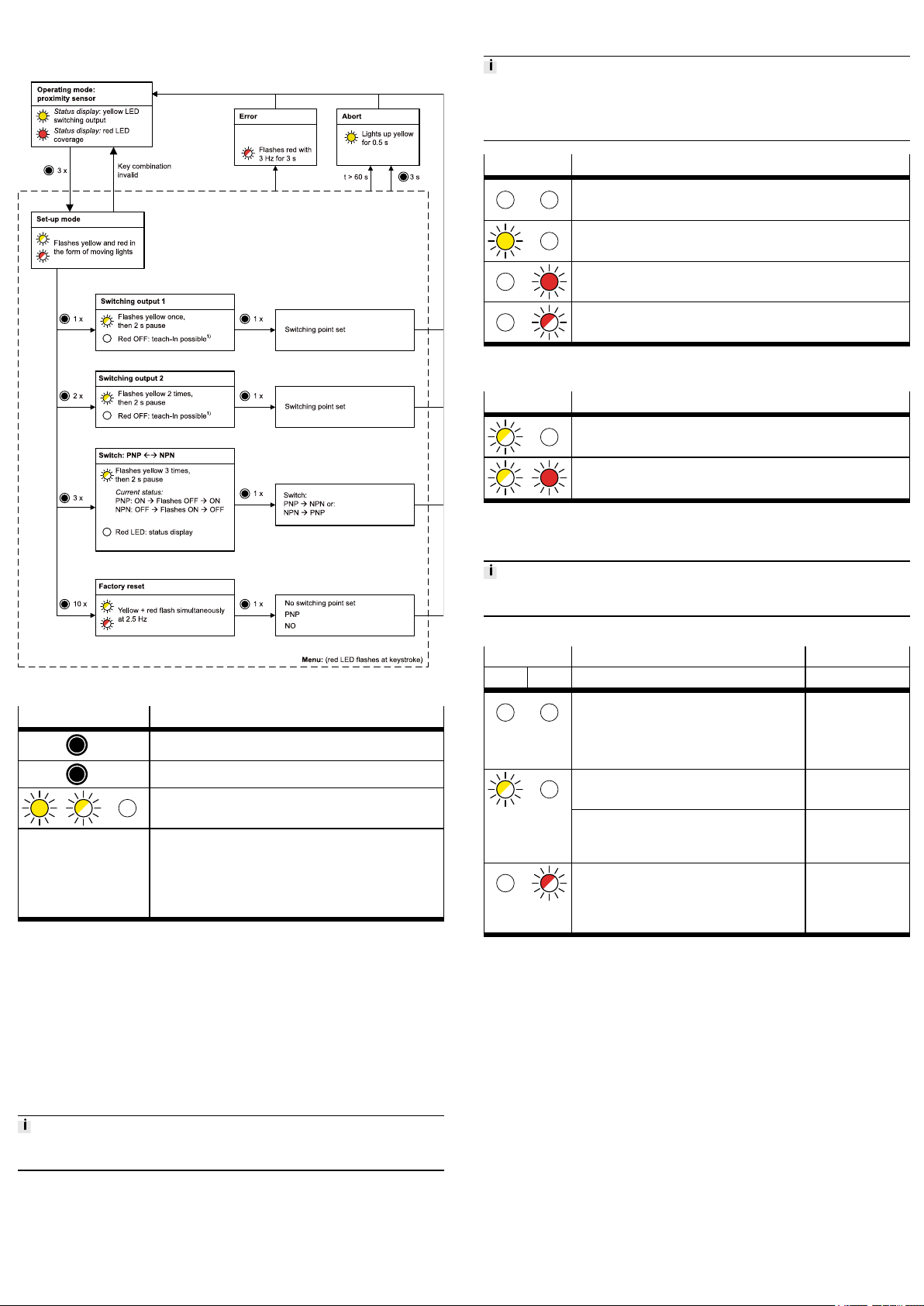
3Red LED: status display
4Yellow LED: switching status dis-
play
5Marking: centre of the sensing
range
6Capacitive operating key
7Retaining screw
Fig. 1 Design of SDAS-MHS
5 Function
The position transmitter detects the magnetic field of the piston magnet and con-
tinuously senses the piston movement in the sensing range. The position trans-
mitter can be operated in one of the following operating modes:
– Cylinder switch with 2 programmable switching points (standard operation) .
– Position transmitter with IO-Link communication .
In the case of active IO-Link communication (IO-Link master required), the SDAS-
MHS switches automatically into the position transmitter operating mode.
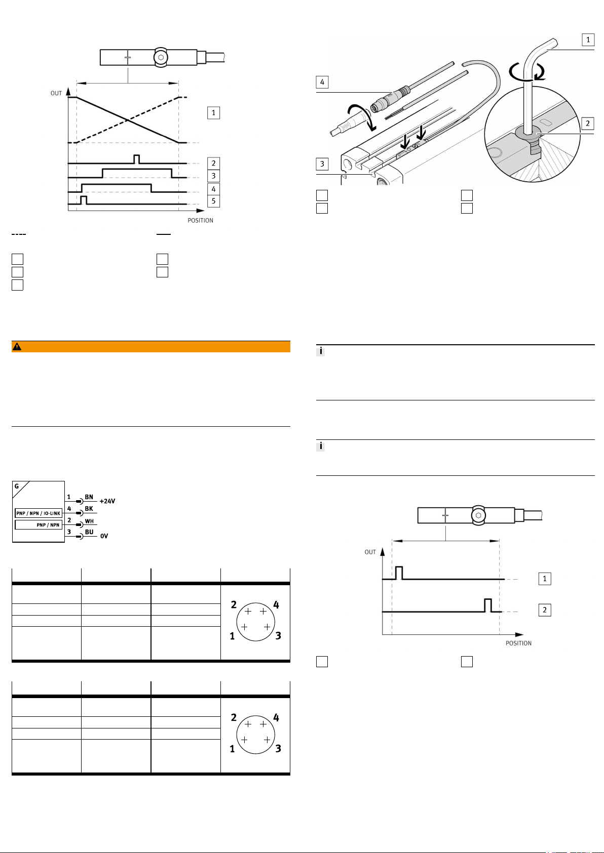
5.1 Cylinder switch operating mode
In the cylinder switch operating mode, 2 switching points can be programmed
within the sensing range.
– Operation using capacitive operating key
– Switching logic: normally open (NO)
– Output signal 24VDC (PNP or NPN)
– Marking on the housing indicates the centre of the sensing range.
1Electrical output 1 2Electrical output 2
Fig. 2 Application example: Cylinder switch operating mode
5.2 Position transmitter operating mode (IO-Link)
In the position transmitter operating mode, programmed switching signals and
the continuous position values (digitally coded analogue values) are transferred.
– Programming via IO-Link
– Device description file IODD èwww.festo.com/sp.
– Capacitive operating key is deactivated.
– Cylinder switches or window comparators or hysteresis comparators can be
programmed individually on 4 switching channels.
– The continuous position values are always transferred in parallel with and
independently of the position value output of the switching channels.
– Each channel can be set to be normally closed (NC) or normally open (NO).
– Data transmission is serially and digitally coded in the IO-Link protocol.
– Process data: 12 bit for position data and 4 bit for switching channels
– Unshielded standard cables of up to 20m in length can be used.
– Parameters and functions in accordance with Smart Sensor profile
– Support for the optional functions “Block parameterisation” and “Data
storage”
8096677
SDAS-MHS
Position transmitter
8096677
2018-07a
[8096679]
Instructions| Operating
Festo AG & Co. KG
Ruiter Straße 82
73734 Esslingen
Germany
+49 711 347-0
www.festo.com