Festo SMAT-8M User manual

Position transmitter SMAT-8M
Festo AG & Co. KG
Postfach
D-73726 Esslingen
+49 711 347 0
www.festo.com
Operating instructions
Original: de
8063047
1604e
[8062992]
Industrial Control Equipment 2MD1
1 Product description
1
2
3
4
5
1Connecting cable
2Mounting screw
3Plug, M8 rotatable
4LED (red) - Piston/gripper not in
measuring range
5LED (green) - Piston/gripper in
measuring range
Fig. 1
2 Function and application
The position transmitter SMAT-8M is an electronic position transmitter with 2D Hall
sensor, integrated signal processing, analogue voltage output and visual status
indicators.
The position transmitter SMAT-8M is intended to be used for contactless detection
of the piston position of drives compatible with magnetic detection. It can be used
with Festo cylinders with T-slot (profile slot 8) as well as round cylinders and tie-
rod cylinders with mounting kits.
The magnetic field of the piston magnet is detected, the magnetic field compon
ents are analysed internally and then, within the working range, is output as an
analogue range-proportional signal. The working range varies depending on the
cylinder.
The SMAT8M is preinitialised at the factory and can be placed in operation
immediately (èchapter 5.1).
The device is not suitable for use as a safety component!
UL Notice
Only applicable if the UL mark is displayed on the product: for compliance with
the approval conditions of Underwriters Laboratories (UL) for USA and Canada,
please observe the following instructions from UL.
– Only for use in Class 2 Circuits.
– Field installed conductors for the position transmitter shall be segregated
from field and factory installed conductors and uninsulated live parts of other
circuits operating at over 150 V to ground so that a minimum permanent
2 inch (50.8 mm) separation is maintained, unless the field wiring conductors
have been provided with recognized insulating material which has an equal or
higher voltage rating than the other circuit involved.
3 Prerequisites for use
Use the product in its original status, without any unauthorised product modific
ations (such as removal of the connecting plug).
Use the SMAT-8M only for the suitable drives from Festo
(èwww.festo.com/catalogue). Festo recommends the use of non-rotating
piston rods or a mechanical structure which provides protection against rota
tion.
Prevent magnetic objects being in close proximity of the SMAT-8M. These could
influence the magnetic field and thereby the behaviour of the sensor.
Do not exceed the limit values (e.g. for operating medium, voltages, forces,
temperatures).
Take into consideration the ambient conditions at the location of use.
The device is intended for use in an industrial environment. Measures may need
to be implemented in residential areas for interference suppression.
Observe the regulations which apply in your location (e.g. from trade associ
ations or from national institutions).
Remove everything used for protection during transport such as protective wax,
films, caps and cardboard boxes. The material used in the packaging has been
specifically chosen for its recyclability (with the exception of the oil-impreg
nated paper which is residual waste).
4 Installation
Installation and commissioning may only be performed in accordance with these
instructions by technicians with appropriate qualifications.
4.1 Mechanical
The retainer can be fitted in any position.
2
1
1Allen key 2T-slot (profile slot 8)
Fig. 2
Caution
Applying too much torque when tightening the mounting screw can damage the
device.
Tighten the mounting screw until finger-tight (max. 0.6 Nm).
1. Insert the SMAT-8M into the slot 2on the drive.
2. Tighten the mounting screw until finger-tight.
– Max. tightening torque 0.6 Nm.
– Tool: Allen key 1(size 1.5 mm).
Mounting instructions for use of mounting kits - General
Mount the SMAT-8M in the slot of the mounting kit so that the front of the
SMAT-8M is flush with the slot.
Mounting instructions for use of the mounting kit SMBR-8-…
The slot of the mounting kit SMBR-8 is not long enough for the SMAT-8M to be
mounted so that the front of the SMAT-8M is flush with the slot.
Push the SMAT-8M 1so far back in the slot that the mounting screw 4is just
able to engage in the slot (èFig. 3).
2
3
41
1SMAT-8M
2mounting kit SMBR-8
3Round cylinder
4Mounting screw
Fig. 3

4.2 Electric
Warning
Use power supplies which guarantee reliable electrical isolation of the operating
voltage as per IEC/EN 60204-1. Consider also the general requirements for PELV
circuits in accordance with IEC/EN 60204-1.
Note
Long signal lines reduce the resistance to interference.
Connect the SMAT-8M to the analogue control input with a connecting cable
which is as short as possible (max. length of connecting cable èchapter 11).
1. Make sure that the operating voltage is switched off.
2. If a connecting cable with an open end is used: connect the wiring as shown in
Fig. 4.
3. If a 4-pin plug connector M8x1 is used: the maximum torque to be applied when
securing the plug is 0.3 Nm.
Circuit diagram (normal operation)
Fig. 4
Pin allocation
Pin Allocation Wire colours 1) Plug
1Operating voltage +24 V DC Brown (BN) M8x1, 4-pin
2Analogue output 0 V White (WH)
30 V Blue (BU)
4Analogue output 0 … 10 V 2) Black (BK)
1) Using a connecting cable with open end
2) The analogue output is connected to the operating voltage in order to initialise the measuring range.
5 Commissioning
5.1 Commissioning without additional initialisation
The SMAT-8M can be put into operation immediately without any additional initial
isation.
1. Switch on the operating voltage.
èThe LED lights up (depending on the piston position èFig. 11).
èThe device is ready for operation.
5.2 Commissioning with initialisation of the measuring range
Note
The initialisation carried out at the factory is a one-time pre-initialisation. Every
new initialisation must be carried out manually.
Customer-specific initialisation is possible for specialised applications (enlarging
the working range, increasing repetition accuracy on grippers and compact cylin
ders, ècatalogue).
Note
External magnetic fields, e.g. from magnetic tools or external structures, affect
the measurements of the SMAT-8M.
When determining the measuring range, move the SMAT-8M without using a
tool if possible or use non-magnetic tools.
Initialise the SMAT-8M in the genuine application environment.
During initialisation, the measuring range of the SMAT-8M is set to the magnetic
properties of the drive.
Re-initialise the SMAT-8M every time the drive is changed.
Use a connecting cable with an open end, e.g. NEBU-M8G4-...-LE4.
Use a separate terminal for the connection to pin 4.
Note
Repetition accuracy is better in the middle of the measuring range than at the
edge.
For critical applications, position the SMAT-8M so that the relevant measuring
points are close to 5.5 V.
Circuit diagram (initialisation)
Fig. 5
Initialising the measuring range when using the SMAT-8M on standard cylinders
Cylinders with a stroke of at least 40 mm are called standard cylinders in this docu
ment.
1. Switch off the operating voltage.
2. Manually move the piston of the standard cylinder into one of two end positions.
Secure the piston rod to prevent it twisting.
3. Connect the SMAT-8M to the operating voltage using the connecting cable with
an open end (èFig. 5). Use a separate terminal for the connection to pin 4.
4. Switch on the operating voltage.
èThe red LED flashes, and the SMAT-8M is ready for initialisation.
Fig. 6
5. Manually insert the SMAT-8M into the slot opposite the position of the piston
(èFig. 6).
6. Slowly push the SMAT-8M in the slot in the direction of the piston until the green
LED lights up.
7. Secure the SMAT-8M in this position (èchapter 4.1).
8. Disconnect pin 4 from the operating voltage, without interrupting the operating
voltage on pin1.
èThe initialised values are saved in the SMAT-8M. They will be retained even
in the event of power failure.
èThe red LED goes out.
èThe green LED lights up. The SMAT-8M is ready for operation.
9. Connect the SMAT-8M to the analogue control input (èFig. 4).
10. If necessary, push the SMAT-8M into the desired measuring position.
Note
If the initialisation process terminates prematurely, the SMAT-8M goes into its
non-initialised status and must be re-initialised. The previous initialisation can
not be reproduced.
If initialisation was not finished correctly or an adequate signal was not detected,
both LEDs will flash at the same time (èchapter 9).
Initialising the measuring range when using the SMAT-8M on compact cylinders
1. Switch off the operating voltage.
2. Manually move the piston into the mid-position of the piston stroke.
3. Connect the SMAT-8M to the operating voltage using the connecting cable with
an open end (èFig. 5). Use a separate terminal for the connection to pin 4.
4. Switch on the operating voltage.
èThe red LED flashes, and the SMAT-8M is ready for initialisation.
Fig. 7
5. Manually insert the SMAT-8M into the slot at the start of the slot (èFig. 7).
6. Slowly push the SMAT-8M in the slot in the direction of the piston until the green
LED lights up (èFig. 7).
7. Keep pushing the SMAT-8M along until the green LED goes out again.

Note
If you keep pushing the SMAT-8M further, the green LED lights up again.
Push the SMAT-8M back until the green LED goes out.
8. Secure the SMAT-8M in this position (èchapter 4.1).
9. Disconnect pin 4 from the operating voltage, without interrupting the operating
voltage on pin1.
èThe initialised values are saved in the SMAT-8M. They will be retained even
in the event of power failure.
èThe red LED goes out.
èThe green LED lights up. The SMAT-8M is ready for operation.
10. Connect the SMAT-8M to the analogue control input (èFig. 4).
Note
If the initialisation process terminates prematurely, the SMAT-8M goes into its
non-initialised status and must be re-initialised. The previous initialisation can
not be reproduced.
If initialisation was not finished correctly or an adequate signal was not detected,
both LEDs will flash at the same time (èchapter 9).
For scaling of the travel range, the SMAT-8M must be initialised a second time
(èchapter 5.3).
Initialising the measuring range when using the SMAT-8M on grippers
1. Switch off the operating voltage.
2. Position the gripper jaws of the gripper by hand in the mid-position of the grip
per stroke.
3. Connect the SMAT-8M to the operating voltage using the connecting cable with
an open end (èFig. 5). Use a separate terminal for the connection to pin 4.
4. Switch on the operating voltage.
èThe red LED flashes, and the SMAT-8M is ready for initialisation.
Fig. 8
5. Manually insert the SMAT-8M into the slot at the start of the slot (èFig. 8).
6. Slowly push the SMAT-8M in the slot towards the middle until the green LED
lights up (èFig. 8).
7. Keep pushing the SMAT-8M along until the green LED goes out again.
Note
If you keep pushing the SMAT-8M further, the green LED lights up again.
Push the SMAT-8M back until the green LED goes out.
8. Secure the SMAT-8M in this position (èchapter 4.1).
9. Disconnect pin 4 from the operating voltage, without interrupting the operating
voltage on pin1.
èThe initialised values are saved in the SMAT-8M. They will be retained even
in the event of power failure.
èThe red LED goes out.
èThe green LED lights up. The SMAT-8M is ready for operation.
10. Connect the SMAT-8M to the analogue control input (èFig. 4).
Note
If the initialisation process terminates prematurely, the SMAT-8M goes into its
non-initialised status and must be re-initialised. The pre-initialisation cannot be
reproduced.
If initialisation was not finished correctly or an adequate signal was not detected,
both LEDs will flash at the same time (èchapter 9).
For scaling of the travel range, the SMAT-8M must be initialised a second time
(èchapter 5.3).
5.3 Scaling the analogue signal
With grippers and compact cylinders, the SMAT-8M returns an analogue signal of
about 4 … 6 V after initialisation of the measuring range, as the piston stroke is
smaller than the working range of the SMAT-8M.
A second initialisation can be used to scale the analogue signal to the mechanical
end ranges.
1. Switch off the operating voltage.
2. Disconnect the SMAT-8M from the analogue input.
3. Connect the SMAT-8M to the operating voltage using the connecting cable with
an open end (èFig. 5). Use a separate terminal for the connection to pin 4.
4. Switch on the operating voltage.
5. Using compressed air, move the piston or the gripper jaws into the two end
positions once.
6. Disconnect pin 4 from the operating voltage, without interrupting the operating
voltage on pin1.
èThe initialised values are saved in the SMAT-8M. They will be retained even
in the event of power failure.
7. Connect the SMAT-8M to the analogue control input (èFig. 4).
Note
If the piston was not exactly in the mid-position during the first initialisation of
the measuring range, the results will show a shift in the signal range
(e.g. 2.5V … 10 V or 1.0 V … 8.3 V etc.). This does not affect the functioning of
the device or its repetition accuracy.
LED displays during initialisation of the measuring range
LED
Green
LED
Red
Description
Piston/gripper jaws are located outside the working range
(range A or C, èFig. 10).
LED Green off,
LED Red flashing.
Piston/gripper jaws are located inside the working range
(range B, èFig. 10).
The green LED does not light up in the middle of the working range (zero
crossover).
LED Green on,
LED Red flashing.
Error during initialisation Adequate signal not detected, or initialisation was
not finished correctly.
Both LEDs flashing
at the same time.
Fig. 9
6 Operating states and signal behaviour
ABC
0 mm 40 mm (max.)
0V
0.5V
1V
10V
Fig. 10

LED displays during operation
LED
Green
LED
Red
Description
Analogue signal >1 V… <10 V:
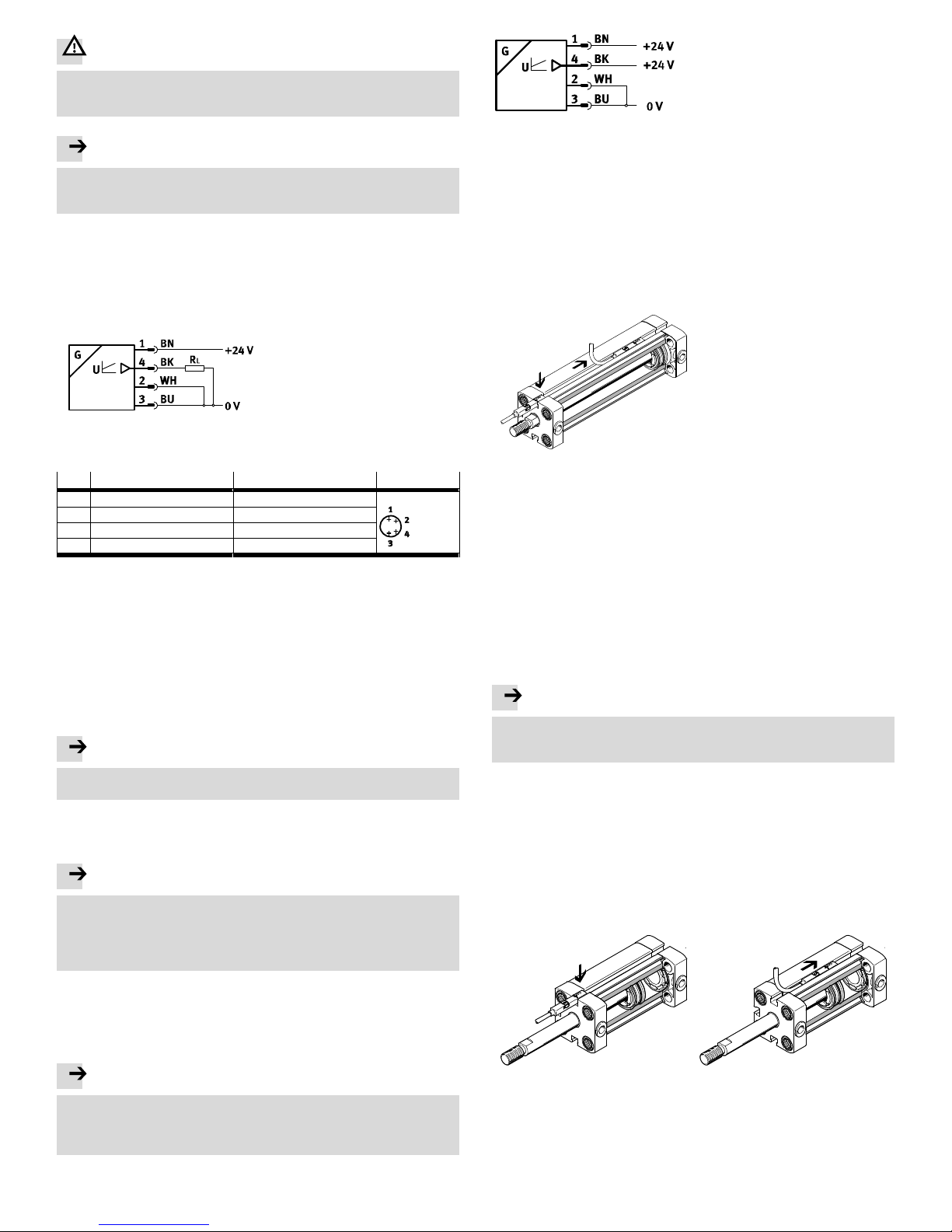
The piston is inside the measuring range (range B, èFig. 10).
LED Green on,
LED Red off.
Analogue signal 0.5 V:
The piston is outside the measuring range (range A or C, èFig. 10) when
operating voltage is switched on. The SMAT-8M cannot detect the piston's
position.
LED Green off,
LED Red on.
Analogue signal1 V:
The piston has exited the measuring range in the negative direction1)
(rangeA, èFig. 10). The SMAT-8M can detect the piston's position.
Analogue signal10 V:
The piston has exited the measuring range in the positive direction2)
(rangeC, èFig. 10). The SMAT-8M can detect the piston's position.
1) The output voltage falls in the negative direction. The piston moves away from the piston rod.
2) The output voltage rises in the positive direction. The piston moves towards the piston rod.
Fig. 11
7 Maintenance and care
Cleaning the outside of the SMAT-8M
1. Switch off the operating voltage.
2. Clean the outside of the SMAT-8M with a soft cloth.
Permissible cleaning agents are soapy water (max. +60 °C) and all non-abrasive
agents.
8 Disassembly
1. Switch off the operating voltage.
2. Disconnect the connecting cable from the SMAT-8M.
3. Undo the mounting screw on the SMAT-8M.
4. Remove the SMAT-8M from the slot.
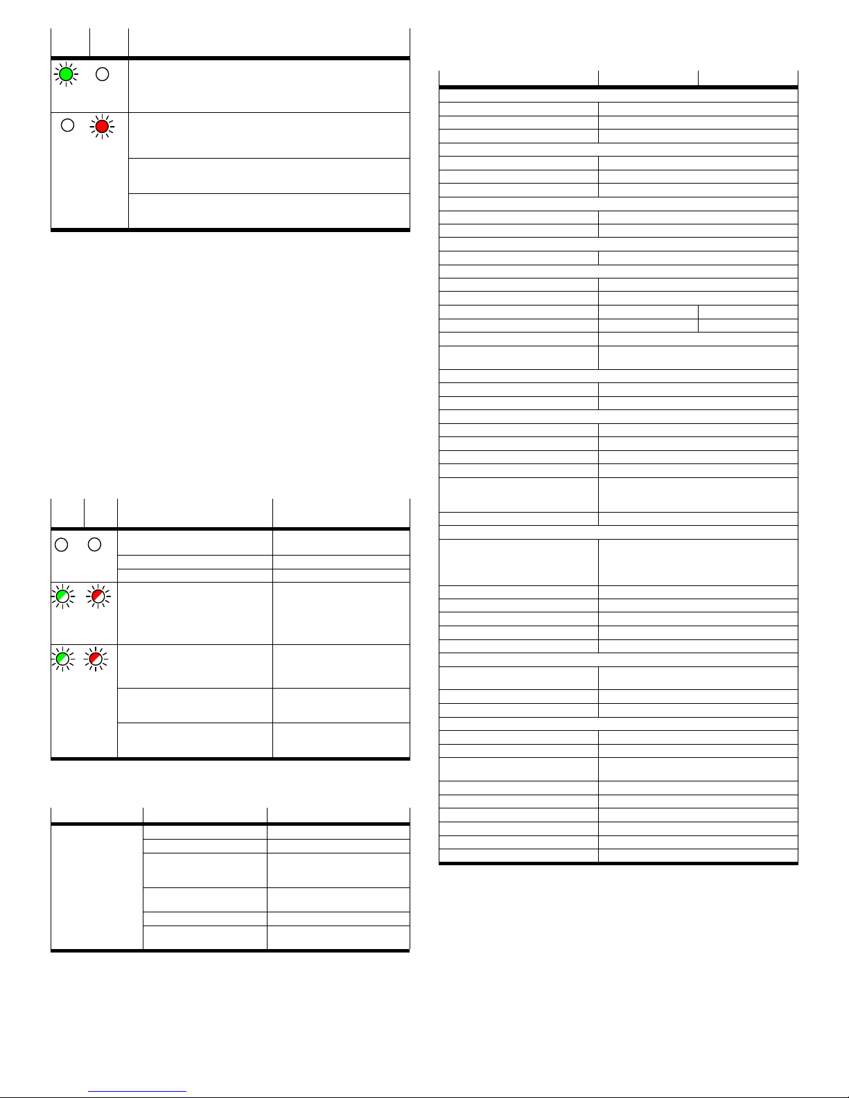
9 Troubleshooting
9.1 Diagnostics via LED
LED
Green
LED
Red
Possible cause Remedy
Faulty power supply. Ensure the power supply
(èFig. 4).
Both LEDs off. Faulty connecting cable. Replace the connecting cable.
Sensor defective. Replace SMAT-8M.
Internal error. Contact your local Festo Service or
LEDs flashing
alternately.
No valid signal.
SMAT-8M not initialised.
Initialise SMAT-8M (èchapter 5.2).
LEDs flashing at
the same time.
Power failure during initialisation. Ensure the power supply and
re-initialise the SMAT-8M
(èchapter5.2).
The magnetic field of the piston/gripper
was not detected correctly by the
SMAT-8M.
Initialise SMAT-8M (èchapter 5.2).
Fig. 12
9.2 General malfunctions
Malfunction Possible cause Remedy
Incorrect or unexpec
ted signals at the ana
logue output.
Unsuitable drive. Use suitable drives only.
SMAT-8M defective Replace SMAT-8M.
No power supply or there is a
non-permissible operating
voltage
Switch on power supply / maintain
permitted operating voltage range
Short circuit or overload at the
output
Remedy short circuit / overload.
Faulty connecting cable. Replace the connecting cable.
Magnetic object in close prox
imity to position transmitter.
Prevent magnetic objects being in
close proximity.
Fig. 13
10 Accessories
Accessories èwww.festo.com/catalogue/SMAT-8M.
11 technical data
technical data Cylinder Grippers
General
Certification RCM Mark, c UL us - Listed (OL)
CE marking (èdeclaration of conformity) In accordance with EU EMC Directive
Note on materials Conforms to RoHS
Input signal/measuring element
Measured variable Item
Measuring principle Magnetic
Measuring range1) [mm] ≤ 40
Signal processing
Max. travel speed [m/s] 3
Typical sampling interval [ms] 2.8
Output, general
Range resolution2) [mm] ≤ 0.05
Analogue output
Analogue output [V] 0 … 10
Sensitivity1) [mm/V] Measuring range/9 V
Linearity error, typ.1) [±mm] 1 0.2
Repetition accuracy [±mm] 0.1 0.025
Capacitive load max. DC [nF] 100
Min. load resistance
Voltage output3)
[kΩ] 2
Output, additional data
Protection against short circuit Yes
Protection against overloading Yes
Electronic components
Rated operating voltage DC [V] 24
Operating voltage DC [V] 15 … 30
Idle current [mA] 15 (Voper = 24 V)
Ready-state delay [ms] ≤ 300
Signal run time, typ. 1) 4) [ms] 14 at v < 0.016 m/s
8.5 at 0.016 < v < 0.05 m/s
5.5 at v > 0.05 m/s
Reverse polarity protection For all electrical connections
Electromechanical components
Cable test conditions Energy chain 50 000 cycles, bending radius 30 mm
Torsional strength min. 300 000 cycles, ±270°/0.1 m
Bending strength according to Festo standard, test
conditions upon request
Cable length [m] 0.3
Max. connecting cable length [m] 30
Electrical connection Cable with plug, M8x1, rotatable thread, 4-pin
Pin contact materials Gold-plated brass
Cable sheath materials TPE-U (PU)
Mechanical components
Type of mounting Screw-type union, for insertion into slot from above,
max. torque 0.6 Nm
Housing materials Reinforced PA6
Union nut materials Nickel-plated brass
Immission/emission
Storage temperature [°C] –25 … +75
Ambient temperature [°C] –25 … +75
Ambient temperature with flex
ible cable installation
[°C] –5 … +70
Recovery time [ms] < 2.8 as per DIN 60947-5-7
IP protection (as per EN 60529) IP65/IP68 (IP68 condition: test duration 24 hrs)
Protection class (as per DIN VDE 0106-1) III
Resistance to shocks (as per EN 60068-2) Severity level 2
Vibration resistance (as per EN 60068-2) Severity level 3
Corrosion resistance class CRC 2
1) Varies depending on the drive used.
2) Range resolution = working range/921 (e.g. 0.027 mm for 25 mm working range).
3) Recommended: connect a resistor to the analogue output, typically 10 kΩ.
4) The signal run time is longer than the scanning interval because of the dynamic filtering. There are three
velocity-dependent filter stages. The examples are valid for a working range of 20 mm.
Other Festo Transmitter manuals

Festo
Festo SDAT-MHS User manual

Festo
Festo SDAS-MHS User manual

Festo
Festo SDAS-MHS User manual

Festo
Festo SDAT-MHS-SV Series User manual

Festo
Festo SDAS-MHS User manual

Festo
Festo SDAT-MHS User manual

Festo
Festo SDAT-MHS-SV Series Reference guide

Festo
Festo SDAT-MHS SA Series Reference guide

Festo
Festo SPTW Series User manual