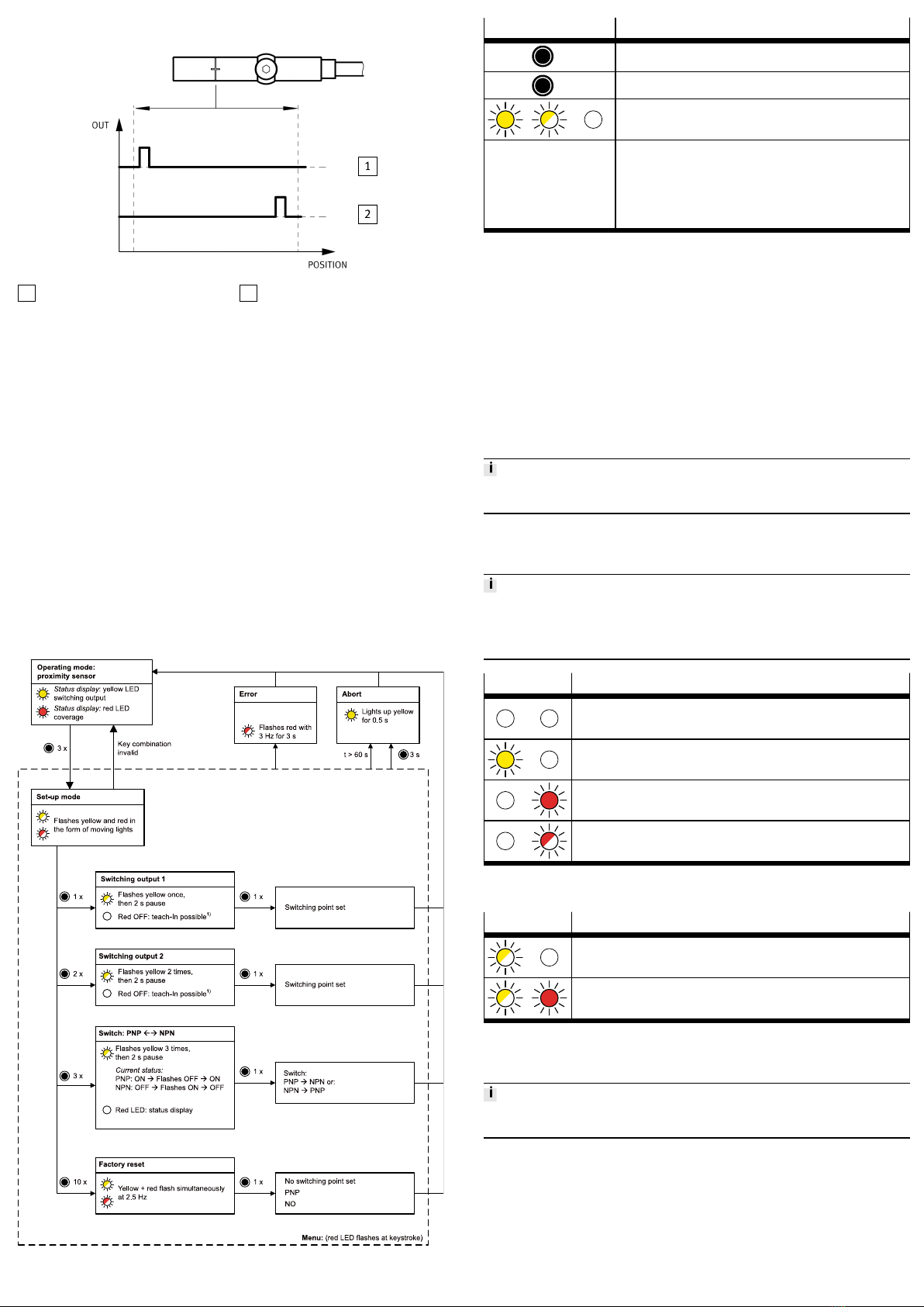
7.1.2 Setting Switching Points
1Electrical output 1 2Electrical output 2
Fig. 6 Application example: Cylinder switch operating mode
1. Move piston to the desired position for switching output 1, within the sensing
range.
ÄRed LED OFF
è Tab. 5 LED Displays in the Proximity Sensor Operating Mode.
2. Activate set-up mode.
3. To assign the position for switching output 1, press the capacitive operating
key 1 time.
ÄThe yellow LED flashes once.
4. Press the capacitive operating key.
ÄSwitching point 1 is established. Operating mode is active.
5. Move piston to the desired position for switching output 2, within the sensing
range.
ÄRed LED OFF
è Tab. 5 LED Displays in the Proximity Sensor Operating Mode.
6. Activate set-up mode.
7. To assign the position for switching output 2, press the capacitive operating
key twice.
ÄThe yellow LED flashes twice.
8. Press the capacitive operating key.
ÄSwitching point 2 is established. Operating mode is active.
7.1.3 Menu structure
Fig. 7 Settings using the capacitive operating key (menu structure)
LED/operating key Meaning
N x Press the capacitive operating key (in the example: 3x); max. 1s
pause between 2 consecutive presses
3s Hold the capacitive operating key pressed for at least 3s.
LED illuminated / LED flashing / LED OFF (in the example: yellow
LED)
1) A switching point can only be set when the red LED is OFF. When the
red LED is flashing at 1.5Hz, the magnet is located in the region of
the operational reserve. It is not possible to set a switching point.
The operational reserve is required for the safe setting of switching
points in the edge region. When the red LED is illuminated, the mag-
net is outside the sensing range. It is not possible to set a switching
point.
Tab. 4 Explanation of symbols
7.2 Position Transmitter Operating Mode
In the position transmitter operating mode, commissioning is carried out in the
higher-order controller of the IO-Link master.
1. Load the device description file IODD (èwww.festo.com/sp) into the inter-
preter of the IO-Link master.
2. For general information on the IO-Link specification and for the Smart Sensor
profile èwww.io-link.com.
3. Connect the position transmitter to the IO-Link master as shown in the circuit
diagram
è Tab. 3 Pin Allocation of Plug Connection for Position Transmitter
Operating Mode.
4. Program the position transmitter. Observe the instructions in the operating
instructions for the IO-Link master.
Errors during commissioning are displayed on the user interface of the IO-Link
master. Programming is blocked.
8 Operation
8.1 Proximity Sensor Operating Mode
The position transmitter is parameterised once it is installed.
• Be mindful of the surface temperature of the capacitive operating key and of
the drive.
• Avoid contamination and moisture on the position transmitter.
LED Meaning
Both LEDs OFF: status indicator.
– Piston within the sensing range
– No switching output set
Yellow LED illuminated: switching status indication.
– Switching output 1 or switching output 2 is active.
Red LED illuminated: status indicator.
– Piston outside the sensing range
Red LED flashing at 1.5 Hz: status indicator.
– Piston is located in the region of the operational reserve.
Tab. 5 LED Displays in the Proximity Sensor Operating Mode
8.2 Position Transmitter Operating Mode
LED Meaning
Yellow LED flashing at 1Hz: ready status.
– IO-Link communication is active.
Red LED lights up and yellow LED flashes: status indicator.
– IO-Link communication is active.
– Piston outside the sensing range
Tab. 6 LED Displays in the Position Transmitter Operating Mode
9 Fault Clearance
Errors during IO-Link operation are displayed on the user interface of the IO-Link
master. The IO-Link switching output is not blocked.