9Pressure transmitter SPTW
EN
14012402.03 03/2015
3. Specications
3. Specications
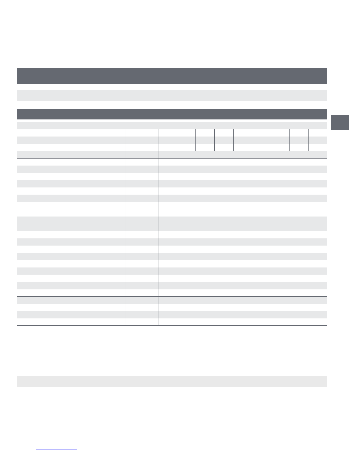
Specications SPTW
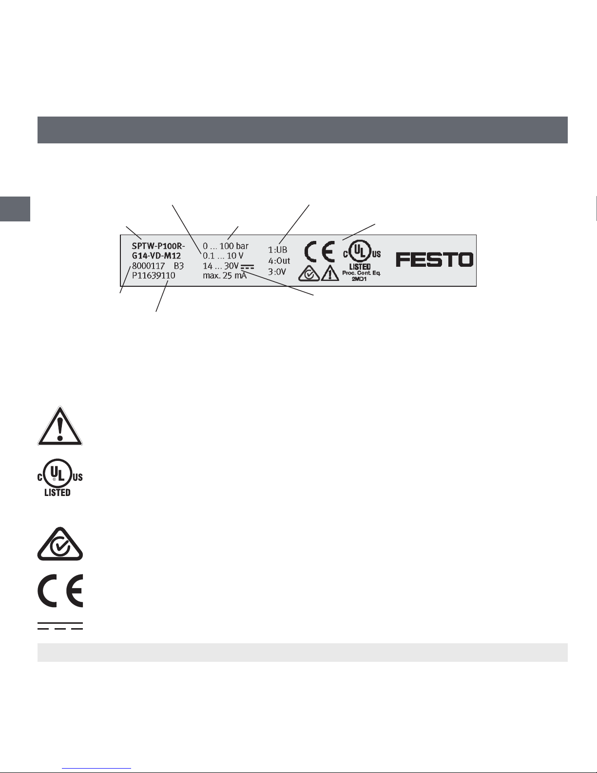
Model designation SPTW- ... B2R B11R P2R P6R P10R P16R P25R P50R P100R
Start of measuring range bar -1 -1 0 0 0 0 0 0 0
End of measuring range bar 1 10 2 6 10 16 25 50 100
Overpressure safety bar 2 20 4 12 20 32 50 100 200
Service life 10 million load cycles
Material
■
Wetted parts
- Process connection Stainless steel 316L
- Pressure sensor Stainless steel 316L (from 0 ... 10 bar rel, 13-8 PH)
■
Internal transmission uid
Silicone oil (only for measuring ranges < 0 ... 10 bar)
■
Case Stainless steel 316L
Power supply UB 1) DC 8 ... 30 V
14 ... 30 V with output 0.1 ... 10 V
Output signal and permissible max. resistive
load RA
RAin ohm 4 ... 20 mA, 2-wire RA ≤ (UB– 8 V) / 0.02 A
0.1 ... 10 V, 3-wire RA> 10 k
Settling time ms < 4
Current supply mA Signal current, max. 25 for current output, max. 8 for voltage output
Insulation voltage DC 500 V
Linearity % FS ≤ ± 0.5 (BFSL) per IEC 61298-2
Accuracy 2) % FS ≤ ± 1.0
Zero oset for the zero signal % FS ≤ 0.5 typ., ≤ 0.8 max.
Repeatability % FS ≤ 0.1
Long-term drift % FS ≤ 0.1 per IEC 61298-2
Signal noise % FS ≤ 0.3
Permissible temperature ranges
■
Medium °C 0 ... +80
■
Ambient °C 0 ... +80
■
Storage °C -20 ... +80
1) The power supply for the pressure transmitter must be made via an energy-limited electrical circuit per UL/EN/IEC 61010-1 or an LPS to UL/EN/IEC 60950-1 or
class 2 per UL1310/UL1585 (NEC or CEC).The power supply must be suitable for operation above 2,000 m should the pressure transmitter be used at this altitude.
Only ever use a power source that ensures a safe electrical isolation of the operating voltage in accordance with IEC/DIN EN 60204-1. In addition, observe the
general requirements for PELV circuits in accordance with IEC/DIN EN 60204-1. Switching power supply units are permissible, if they ensure a safe isolation as
dened by IEC/EN 60950-1.
2) Including linearity, hysteresis, zero oset and end value deviations (corresponds to measured error per IEC 61298-2). Calibrated in vertical mounting position with
process connection facing downwards.