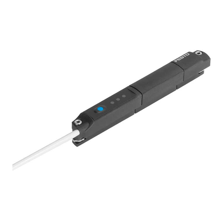
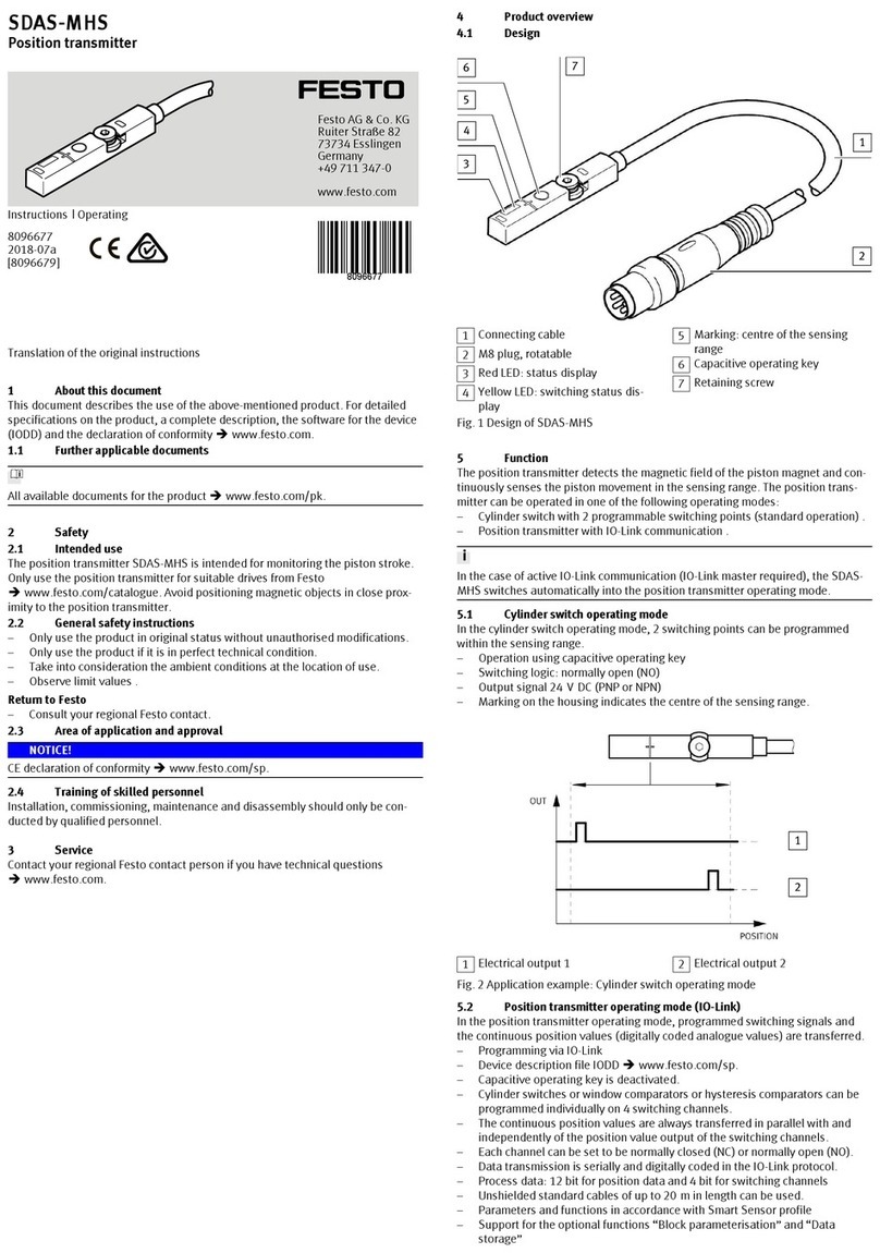
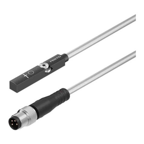
Festo SDAS-MHS User manual

8091014
SDAS-MHS
Position transmitter
8091014
2018-06
[8091016]
Description|Function,
Operating

Translation of the original instructions
2 Festo — SDAS-MHS — 2018-06

3Festo — SDAS-MHS — 2018-06
1 About this document................................................................................................... 5
1.1 Further applicable documents...................................................................................... 5
2 Safety........................................................................................................................... 5
2.1 Intended use................................................................................................................ 5
2.2 General safety instructions........................................................................................... 5
2.3 Area of application and approval.................................................................................. 5
2.4 Training of qualified personnel..................................................................................... 5
3 Product overview......................................................................................................... 6
3.1 Design........................................................................................................................... 6
3.2 Characteristics.............................................................................................................. 7
4 Function........................................................................................................................7
4.1 Cylinder switch operating mode................................................................................... 8
4.1.1 Cylinder switch function..........................................................................................9
4.2 Position transmitter operating mode (IO-Link).............................................................. 10
4.2.1 Cylinder switch function..........................................................................................11
4.2.2 Window comparator................................................................................................12
4.2.3 Hysteresis comparator............................................................................................13
4.2.4 Switching logic, normally open (NO) and normally closed (NC)...............................14
4.3 Additional information on the operating modes........................................................... 14
5 Installation.................................................................................................................. 16
5.1 Electrical installation.................................................................................................... 16
5.2 Mechanical installation................................................................................................. 17
6 Commissioning............................................................................................................ 17
6.1 Cylinder switch operating mode................................................................................... 18
6.1.1 Activating set-up mode...........................................................................................18
6.1.2 Set switching points................................................................................................19
6.1.3 Changing the configuration of the switching outputs..............................................19
6.1.4 Menu structure....................................................................................................... 20
6.2 Position transmitter operating mode............................................................................ 21
7 Operation..................................................................................................................... 21
7.1 Cylinder switch operating mode................................................................................... 21
7.1.1 LED display............................................................................................................. 22
7.1.2 Reset to factory setting...........................................................................................22
7.2 Position transmitter operating mode............................................................................ 22
7.2.1 LED display............................................................................................................. 22
7.2.2 Reset to factory setting...........................................................................................23
8 Fault clearance............................................................................................................ 23
8.1 Diagnostics via LED...................................................................................................... 23
8.2 General malfunctions................................................................................................... 24
9 Disassembly................................................................................................................ 24
Table of contents
10 Technical data.............................................................................................................. 25
10.1 General..........................................................................................................................25
10.2 IO-Link...........................................................................................................................26
4 Festo — SDAS-MHS — 2018-06

5Festo — SDAS-MHS — 2018-06
1 About this document
This document describes the use of the above-mentioned product.
1.1 Further applicable documents
All available documents for the product èwww.festo.com/pk.
2 Safety
2.1 Intended use
The position transmitter SDAS-MHS is intended for monitoring the piston stroke. Only use the position
transmitter for suitable drives from Festo èwww.festo.com/catalogue. Avoid positioning magnetic
objects in close proximity to the position transmitter.
2.2 General safety instructions
– Only use the product in original status without unauthorised modifications.
– textvar object does not exist
– Take into consideration the ambient conditions at the location of use.
– Observe limit values è 10 Technical data.
Return to Festo
– Consult your regional Festo contact.
2.3 Area of application and approval
NOTICE!
CE declaration of conformity èwww.festo.com/sp.
2.4 Training of qualified personnel
Installation, commissioning, maintenance and disassembly should only be conducted by qualified per-
sonnel.
About this document

3 Product overview
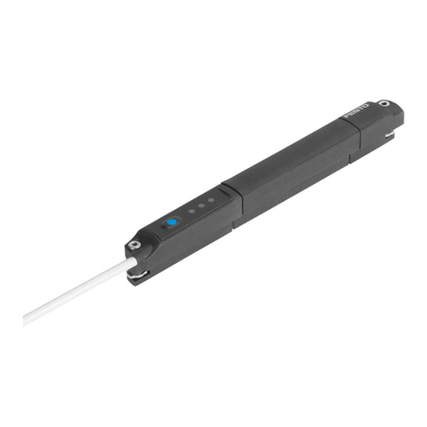
3.1 Design
1Connecting cable
2M8 plug, rotatable
3Red LED: status display
4Yellow LED: switching status display
5Marking: centre of the sensing range
6Capacitive operating key
7Retaining screw
Fig. 1 Design of SDAS-MHS
Product overview
6 Festo — SDAS-MHS — 2018-06

3.2 Characteristics
Characteristic Value Description
Position transmitter SDAS-
Sensor version M Insertable in slot
Sensor principle HS- Hall sensor
Measuring range M40- Typically up to 40mm
Nominal operating voltage 1 24VDC
Display L- LED
Electrical output 1 PNLK- PNP or NPN or IO-Link
Electrical output 2 PN- PNP or NPN
Cable characteristic E- Suitable for use with energy chains/robots
0.3- 0.3mCable length
2.5- 2.5m
Outgoing circuit –Axial
LE Open endElectrical connection
M8 M8 plug
Tab. 1 Overview of variants
4 Function
The position transmitter detects the magnetic field of the piston magnet and continuously senses the
piston movement in the sensing range. The position transmitter can be operated in one of the follow-
ing operating modes:
– Cylinder switch with 2 programmable switching points (standard operation)
è 4.1 Cylinder switch operating mode.
– Position transmitter with IO-Link communication
è 4.2 Position transmitter operating mode (IO-Link).
In the case of active IO-Link communication (IO-Link master required), the SDAS-MHS switches auto-
matically into the position transmitter operating mode.
Function
7Festo — SDAS-MHS — 2018-06

4.1 Cylinder switch operating mode
In the cylinder switch operating mode, 2 switching points can be programmed within the sensing
range.
– Operation using capacitive operating key
– Switching logic: normally open (NO)
– Output signal 24VDC (PNP or NPN)
– Marking on the housing indicates the centre of the sensing range.
1Electrical output 1 2Electrical output 2
Fig. 2 Application example: Cylinder switch operating mode
Function
8 Festo — SDAS-MHS — 2018-06

4.1.1 Cylinder switch function
Output signal Hysteresis
1Teach-in point
Fig. 3 Cylinder switch function
– The teach-in point is located in the centre of the switching window.
– The switching window and hysteresis are preset and cannot be changed.
Function
9Festo — SDAS-MHS — 2018-06

4.2 Position transmitter operating mode (IO-Link)
In the position transmitter operating mode, programmed switching signals and the continuous posi-
tion values (digitally coded analogue values) are transferred.
– Programming via IO-Link
– Device description file IODD èwww.festo.com/sp.
– Capacitive operating key is deactivated.
– Cylinder switches or window comparators or hysteresis comparators can be programmed individu-
ally on 4 switching channels.
– The continuous position values are always transferred in parallel with and independently of the
position value output of the switching channels.
– Each channel can be set to be normally closed (NC) or normally open (NO).
– Data transmission is serially and digitally coded in the IO-Link protocol.
– Process data: 12 bit for position data and 4 bit for switching channels è 10 Technical data.
– Unshielded standard cables of up to 20m in length can be used.
– Parameters and functions in accordance with Smart Sensor profile
– Support for the optional functions “Block parameterisation” and “Data storage”
– The direction of increase of the process data values (PDV) can be inverted. As delivered: lowest
PDV at cable end
Output signal (PDV): direction of increase
inverted
Output signal (PDV): direction of increase
as delivered
1PDV (position data values)
2SSC1 (switching signal channel)
3SSC2
4SSC3
5SSC4
Fig. 4 Application example: Position transmitter operating mode
Function
10 Festo — SDAS-MHS — 2018-06

4.2.1 Cylinder switch function
Output signal Hysteresis
1Teach-in point
Fig. 5 Cylinder switch function
– The teach-in point is located in the centre of the switching window.
– The switching window and hysteresis are preset and cannot be changed.
Function
11Festo — SDAS-MHS — 2018-06

4.2.2 Window comparator
Output signal Hysteresis
1Teach-in point 1 2Teach-in point 2
Fig. 6 Window comparator
The teach-in points are linked to the window comparator function.
– The window width is determined by the position of the teach-in points.
– The hysteresis is preset and cannot be changed.
Function
12 Festo — SDAS-MHS — 2018-06

4.2.3 Hysteresis comparator
1Teach-in point 1 2Teach-in point 2
Fig. 7 Hysteresis comparator
The teach-in points are linked to the hysteresis comparator function.
– Teach-in point 1 is the switch-on point, teach-in point 2 is the reset point.
– The distance between teach-in point 1 and teach-in point 2 determines the size of the hysteresis.
Function
13Festo — SDAS-MHS — 2018-06

4.2.4 Switching logic, normally open (NO) and normally closed (NC)
1Normally open (NO) 2Normally closed (NC)
Fig. 8 Inverting the SSC
The switching logic normally open (NO) is set as standard. The function of the SSC is inverted by
selecting the switching logic normally closed (NC).
4.3 Additional information on the operating modes
The binary data channels SSC1 and SSC2 for the position transmitter operating mode correspond to
the electrical switching outputs 1 and 2 for the cylinder switch operating mode.
Parameterising SSC1 and SSC2 via IO-Link makes it possible to use the window comparator and hys-
teresis comparator switching functions and the switching logic (NO/NC) in cylinder switch operating
mode too. Conversely, the switching points set in cylinder switch operating mode are directly available
in the position transmitter operating mode.
The switching logic for SSC1 set in the position transmitter operating mode applies to SSC1 and SSC2
in the cylinder switch operating mode, regardless of what has been set for SSC2.
An LED is available to display both switching outputs:
– Switching logic NC: the output signal for both switching outputs is AND-gated on the LED display.
– Switching logic NO: the output signal for both switching outputs is OR-gated on the LED display.
Function
14 Festo — SDAS-MHS — 2018-06

1SSC1 = Switching output 1
2SSC2 = Switching output 2
3SSC3
4SSC4
Fig. 9 Relationship of position transmitter and cylinder switch operating modes
Position transmitter Cylinder switch Switching logic in cylinder switch
operating mode
SSC 1 ←→ Switching output 1 As set for SSC1
[or NO: factory setting]
SSC 2 ←→ Switching output 2 As set for SSC1
[or NO: factory setting]
SSC 3 Ignored; settings remain in
memory
Ignored; setting remains in
memory
SSC 4 Ignored; settings remain in
memory
Ignored; setting remains in
memory
Tab. 2 Relationship between the operating modes
Function
15Festo — SDAS-MHS — 2018-06

5 Installation
5.1 Electrical installation
WARNING!
Risk of injury due to electric shock.
• For the electrical power supply, use only PELV circuits in accordance with IEC 60204-1/EN 60204-1
(Protective Extra-Low Voltage, PELV).
• Observe the general requirements of IEC 60204-1/EN 60204-1 for PELV circuits.
• Only use voltage sources that ensure a reliable electric separation from the mains network in
accordance with IEC 60204-1/EN 60204-1.
1. Switch off operating voltage.
2. Connect the M8 plug to the connecting cable of the higher-order controller è Fig.11,4.
– Tightening torque for the union nut of the plug: max. 0.3Nm
Fig. 10 Circuit diagram
Pin Wire colour Allocation Plug
1 Brown (BN) Operating voltage
+24VDC
2 White (WH) Switching output 2
3 Blue (BU) 0V
4 Black (BK) Switching output 1
M8x1, 4-pin
Tab. 3 Pin allocation of plug connection for cylinder switch operating mode
Installation
16 Festo — SDAS-MHS — 2018-06

Pin Wire colour Allocation Plug
1 Brown (BN) Operating voltage
+24VDC
2 White (WH) Not used
3 Blue (BU) 0V
4 Black (BK) IO-Link
M8x1, 4-pin
Tab. 4 Pin allocation of plug connection for position transmitter operating mode
5.2 Mechanical installation
1Hexagon socket spanner
2Retaining screw
3T-slot (profile slot 8)
4M8 plug
Fig. 11 Mechanical installation
1. Insert the position transmitter into the T-slot of the drive.
2. Move the piston into an end position of the application.
3. Push the position transmitter in the direction of the piston until the red LED goes out.
4. Tighten the hexagon socket-head bolts (spanner size: 1.5mm).
– Tightening torque: max. 0.5Nm
6 Commissioning
• Switch on the operating voltage.
ÄThe position transmitter is ready for operation.
Commissioning
17Festo — SDAS-MHS — 2018-06

6.1 Cylinder switch operating mode
The position transmitter is parameterised once it is installed.
• Be mindful of the surface temperature of the capacitive operating key and of the drive.
• Avoid contamination and moisture on the position transmitter.
6.1.1 Activating set-up mode
• Press the capacitive operating key 3 times within 3s.
ÄSet-up mode active: yellow and red LEDs flash alternately.
If programming is not completed within 60s of starting set-up mode, the SDAS-MHS automatically
switches into the operating mode.
Commissioning
18 Festo — SDAS-MHS — 2018-06

6.1.2 Set switching points
1Electrical output 1 2Electrical output 2
Fig. 12 Application example: Cylinder switch operating mode
1. Move piston to the desired position for switching output 1, within the sensing range.
ÄRed LED OFF è Tab. 6 LED displays in the cylinder switch operating mode.
2. Activate set-up mode.
3. To assign the position for switching output 1, press the capacitive operating key 1 time.
ÄThe yellow LED flashes 1 time.
4. Press the capacitive operating key.
ÄSwitching point 1 is established. Operating mode is active.
5. Move piston to the desired position for switching output 2, within the sensing range.
ÄRed LED OFF è Tab. 6 LED displays in the cylinder switch operating mode.
6. Activate set-up mode.
7. To assign the position for switching output 2, press the capacitive operating key 2 time.
ÄThe yellow LED flashes 2 times.
8. Press the capacitive operating key.
ÄSwitching point 2 is established. Operating mode is active.
6.1.3 Changing the configuration of the switching outputs
The switching outputs are configured as PNP as standard. Carry out the following steps to change the
configuration of the switching outputs:
1. Activate set-up mode.
2. To switch into the change-over mode, press the capacitive operating key 3 times.
ÄThe yellow LED indicates the current configuration (flashes 3x/2s pause).
– PNP: ON > Flashes > ON
– NPN: OFF > Flashes > OFF
3. To change the configuration, press the capacitive operating key 1 time.
ÄChange to configuration is stored. Device is ready for operation.
Commissioning
19Festo — SDAS-MHS — 2018-06

6.1.4 Menu structure
Fig. 13 Settings using the capacitive operating key (menu structure)
Commissioning
20 Festo — SDAS-MHS — 2018-06
Other manuals for SDAS-MHS
2
Table of contents
Other Festo Transmitter manuals

Festo
Festo SPTW Series User manual

Festo
Festo SDAT-MHS User manual

Festo
Festo SMAT-8M User manual

Festo
Festo SDAT-MHS-SV Series User manual

Festo
Festo SDAT-MHS SA Series Reference guide

Festo
Festo SDAT-MHS-SV Series Reference guide

Festo
Festo SDAS-MHS User manual

Festo
Festo SDAT-MHS User manual

Festo
Festo SDAS-MHS User manual
Popular Transmitter manuals by other brands

Pepperl+Fuchs
Pepperl+Fuchs Barcon PPC operating instructions

Siemens
Siemens SITRANS P300 operating instructions

Transmitter Solutions
Transmitter Solutions Firefly manual

SC&T
SC&T HE05B Series manual

Jamara
Jamara CCX Lipo Instruction

Dwyer Instruments
Dwyer Instruments 641B Series Installation and operating instructions