Dynatronics Hausmann 6175 Installation instructions

IU-6175 Rev 2 Page 1of 6©2018 HAUSMANN INDUSTRIES
130 Union St • Northvale NJ 07647 USA • Tel: (201) 767-0255 • Fax: (201) 767-1369 • www.hausmann.com
Installation/Operation Instructions
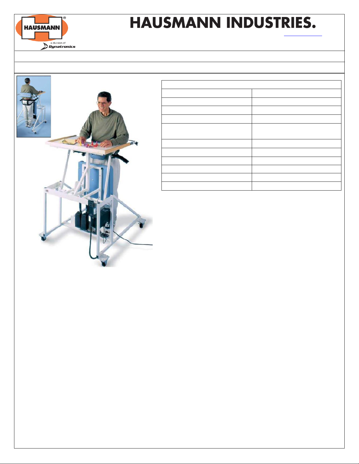
Model 6175 –Stand-In Table
Standard Features:
Hand control operates electric table-top height and motorized
patient lift.
Kid White high pressure laminate top 33” wide x 24” deep
with cutout 19” wide x 10” deep.
Heavy gauge steel frame in cream powder coated finish.
(4) Locking 3” diameter heavy-duty casters.
TOOLS REQUIRED
Crescent Wrench (included)
3/8”Allen Key (included)
3/16”Allen Key (included)
Above tools are required for periodic adjustments –Keep handy near unit.
A. General Purpose:
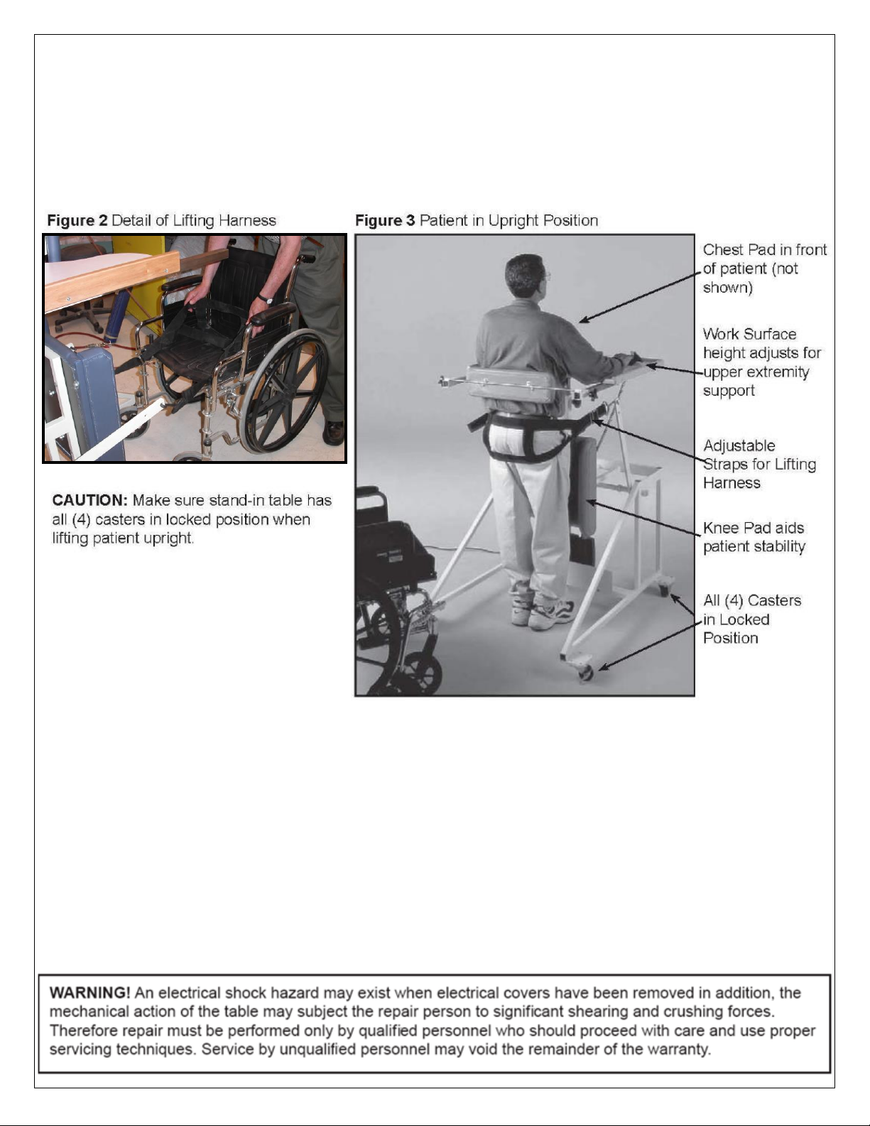
To assist in lifting the patient from a sitting position in a wheelchair to a standing position.
NOT INTENDED AS A PATIENT MOBILITY OR TRANSPORT DEVICE.
B. Setup Instructions:
1. Unpack and set the table in the desired location.
2. Check the table to ensure that all parts are included in the shipment. Inspect the power cord, plug, controls, frame
and upholstery for any damage.
3. The chest pad is shipped in an inverted down position below work surface to avoid shipping damage. Before use,
remove both sliding bars and reconfigure and re-insert chest pad back into the unit so that the chest pad is centrally
located as shown below in figure 1.
4. If any part is missing (see illustration drawing and parts list on page 5) or damaged, please call Hausmann Customer
Service.
5. Provide ample clearance around, above and below the table.
6. For safety and stability securely lock all four casters before using the product.
7. The unit is shipped with a 3-pole male plug, to maintain adequate grounding; the unit must be plugged into a 3-pole
receptacle (preferably a hospital grade) that is correctly wired to the building power system.
Product Specifications
Power Requirements
115 Volts, 110 VAC
Current
3.5 Amps
Frequency
60 Hz
Phase
Single Phase
Laminated wooden table top
with raised rim
33”wide x 24”deep
Table top cut-out
19” wide x 10” deep
Height Range
42 ½” to 52 ½”
Lifting Capacity
300 lbs
Width
36 ½”
Depth
43”
Top Capacity
100 lbs

IU-6175 Rev 2 Page 2of 6©2018 HAUSMANN INDUSTRIES
C. Precautions:
NEVER leave the patient unattended.
ALWAYS keep children away from the table.
ALWAYS inform the patient of the procedure before beginning adjustment to table. Also advise the patient prior to
making any further adjustments to the table while the patient is positioned on the table.
NEVER place hands or feet near moving mechanisms while raising or lowering the table.
NEVER use table to transport patient.
ALWAYS keep casters locked when patient is using the table.
DANGER: Risk of explosion hazard if used in the presence of flammable anesthetics.
NOTE: Routinely check to ensure harness strap is routed properly through the buckle, to prevent accidental
loosening of the harness.
WARNING: Never roll patient into lifting position before locking all four casters.
D. Operating Instructions
A daily check and preliminary operation of the controls for the table is recommended to ensure proper mechanical
operation prior to placing a patient on the table.
1. Securely lock all four casters and place the patient’s wheelchair up to the stand-in table.
2. Adjust the width clearance of the table’s lift arms by loosening the Allen screw in each arm collar by using a
3/16” Allen wrench (included).
3. Move collars and arms laterally along the horizontal hex rod for desired width and re-lock collars in place. Lift
arms can be adjusted from 21” to 27” wide.
CAUTION: Make sure lift arms do not infringe upon padded knee rest.
4. Position the harness under and around the patient’s buttocks with lift arms in a down position, as shown in
figure 2.
5. Attach the hooks in the appropriate slot with the face (open end) pointing outward. Use either of the two hole
locations on the arms.

IU-6175 Rev 2 Page 3of 6©2018 HAUSMANN INDUSTRIES
6. The harness length can be adjusted as required by use of the buckles and straps located on each side of the
harness. The buckle strap must be looped through the buckle to be properly secured.
7. Ensure the patient’s toes are to the toe plate and knees are on the knee pad.
8. Using the hand-held control, activate the motor drives to raise the patient from sitting to a standing position.
9. Once the full upright standing position is reached, adjust the chest pad to desired height, then lock the back
support into position. You may now also adjust the height of the table using the hand-held control.
10. To lower the patient back to the wheelchair, reverse the procedure.
E. Cleaning and Disinfecting Surfaces
1. Unplug the power cord before cleaning or disinfecting.
2. Periodically wipe the table off with a damp cloth or with mild soap and water.
3. Disinfect the table top by scrubbing with an approved germicidal solution. After scrubbing, rinse with a wet
cloth and allow to dry.
4. Ensure your hands are dry and the power cord and plug assembly are dry when reconnecting the power cord.
F. Maintenance
Perform the following actions periodically to maintain the product.
1. Wipe table off with damp cloth or mild soap and water to maintain finish.
2. Inspect the power cord and plug for frayed wires and/or damaged insulation.
3. The joints use oil impregnated bronze bushings and should not require lubrication.

IU-6175 Rev 2 Page 4of 6©2018 HAUSMANN INDUSTRIES
The table described in this manual offers some user-serviceable parts. This section offers suggestions for periodic
maintenance inspections as well as instructions for specific service or repair that may be performed by the user. For
assistance with any service-related matter or to obtain needed replacement parts, contact your sales representative or
distributor.
NOTE: Only technically qualified personnel should attempt to service or repair this equipment.
If needed, a touch-up paint kit is available. Contact your sales representative or distributor.
G. Trouble Shooting Guide
Should the unit fail to operate, follow the checks below:
Check to ensure that the power cord is plugged in properly and the wall outlet is working.
Check to ensure the plug is fully inserted at its connections at both ends of the cord.
The motor is protected by a thermal overload device. Should this safety device trip or disengage, let the motor
cool for 15 minutes before operation.
If the table is still inoperable, contact your sales representative or distributor.
H. Upper and Lower Limit Switches
CAUTION! The upper and lower limits switches are located inside the motor gearbox assembly. They are pre-set at the
factory and should NOT be adjusted. Any adjusting or tampering of limit switches will void the warranty and
could cause personal injury and/or damage to the table.
I. Warranty
Hausmann Industries, Inc. warrants each Hausmann product to be free of defects in material and workmanship, and
agrees to remedy any such defect or to furnish a new equal part in exchange therefore. This warranty covers defects in
materials and workmanship for three years from date of original purchase, provided such product is used for the normal
purpose for which intended and damage is not the result of abuse or misuse.
Please join Hausmann’s effort to reduce paper use and keep the planet green by using our paperless
Warranty Registration form. Visit www.hausmann.com and click on Warranty Registration. If you do not
have web access or prefer the form be mailed or faxed to you, please call Hausmann Customer Service.

IU-6175 Rev 2 Page 5of 6©2018 HAUSMANN INDUSTRIES
Item
Description
Quantity
A
Work Surface
1
B
Adjustable Chest Pad
1
C
Hand Control w/ Coil Cord
1
D
Back Brace Control Knob
2
E
Sliding Back Brace Pad
1
F
3” diameter locking caster
4
G
Steel toe plate
1
H
3/16” locking allen hex collar for lift arm
2
I
Lift arm rotating hex rod
1
J
Upholstered Knee Pad
1
K
Lifting harness with adjustable straps
1
L
Lift arms
2
M
Chest pad height control knob
2
N
Vertical work surface lifting column
1
O
9’ Power cord w/ grounded plug
1
P
Work surface motor (plugs into control box)
1
Q
Lift arm motor
1
R
Control Box
1
B
M
E
D
C
L
O
F
F
N

IU-6175 Rev 2 Page 6of 6©2018 HAUSMANN INDUSTRIES
A
A
B
D
D
C
Table of contents
Other Dynatronics Medical Equipment manuals

Dynatronics
Dynatronics Solaris Plus D715T User manual

Dynatronics
Dynatronics Dynatron T3 User manual

Dynatronics
Dynatronics Dynatron 850 Plus User manual

Dynatronics
Dynatronics Dynatron 825 User manual

Dynatronics
Dynatronics dynatron solaris 709 plus User manual

Dynatronics
Dynatronics DYNATRON SmarTRAC User manual
Popular Medical Equipment manuals by other brands

OAKWORKS
OAKWORKS Clodagh Gemini user manual

Gioco
Gioco CryoTec Quick setup guide

Neuroelectrics
Neuroelectrics Enobio 8 Getting started

Johnson & Johnson
Johnson & Johnson DePuy Synthes Electric Pen Drive user manual

Ohmeda
Ohmeda Ohio 2000 Series Operation and maintenance manual

Caresono
Caresono PadScan HD2 user manual