Spinlock Powerclutch XTR Quick start guide

Description
A mid load rope holding clutch, for conventional and low stretch lines of
8-12mm. Product codes denote rope range in mm.
See www.spinlock.co.uk for full technical specification.
Use
Open the handle fully forward to the thread line through the clutch. With the
handle closed, the clutch will hold the rope automatically as the load is eased
from the winch. (Allow for a forward rope movement of up to 20mm (1”) as the
cam engages. Gripping performance on new rope will improve with use.
To Release: XTR clutches have a two stage release action. For the first stage
you feel no load on the handle. The second stage releases the line.
Installation
• Decide the most efficient clutch layout before marking out and drilling 8.5mm
(11/32”) holes.
• Install clutch forward of the winch with the handle opening towards the load,
keeping the rope deflection angle as small as possible. In a bank of clutches,
try to ensure that the most heavily loaded lines have the least deflection.
• The angle of the line from the clutch up to the winch drum, should not
exceed 10°. You can reduce this angle by increasing clutch to winch distance or
raising the clutch using a wood or delrin (t.m.) pad.
• Insert correct stainless steel M8 (5/16") cap or hex head fasteners using full
nuts and washers.
• Apply silicone sealant around the thread of the fasteners to ensure a
watertight seal and easy removal.
• Ensure that the clutch is securely fitted to the deck. Do not overtighten the
fixings.
• Extra reinforcement is needed for foam sandwich deck installations:
please consult your local boatyard.
• For side mounting use conversion kit XTR-SMNT.
• Rinse the gripping area of new rope in sea water before use.
Powerclutch XTR
La garantie du fabricant est de 5 ans, soumise aux conditions publiées par
Spinlock.
Installation and Use • Installation et Utilisation • Installation und Gebrauch
5 Jahre Hersteller-Garantie, unter den von Spinlock veröffentlichten Vertrags-
Bedingungen.
5 year manufacturer’s warranty subject to published Spinlock terms and
conditions.
Maintenance
Spinlock products are made from the best quality materials for durability and low
maintenance in a harsh marine environment.
• Flush regularly with fresh water.
• Inspect product carefully before each new session.
• Do not use mineral oil or solvent based lubricants like "WD40". The wrong
lubricants will degrade and weaken the moulded composite components and can
cause sudden structural failure. They will also degrade the bearing properties of
composite bushes.
• When removing the cam and handle use text and diagram from ‘spares’ kit.
Service
To help ensure a long working life for every Spinlock product, we supply easily
installed parts and performance upgrades through Spinlock stockists worldwide.
See www.spinlock.co.uk for full listing.
General Guidance
The maximum load achievable in practice is a function of rope diameter and
construction: generally the bigger and firmer the rope, the better the load holding.
Safety
Please take care to follow these important safety rules:
• Check that the clutch is correctly specified for your application
• Check carefully that it is correctly installed before using it for the time under
load.
• Safely release the rope by controlling it on a winch drum.
• Never open the handle when clutch is heavily loaded as sudden release may
cause injury, and can damage rope, rig or clutch.
• Use braided rope only (never use three strand or wire rope).
• Never use the clutch with damaged rope.
• Never use polysulphide or polyyrethene based sealant which can degrade the
product.
• Do not modify any part of the clutch.
• Always use hand protection.
Safety Warning
This product is designed for use on sailboats. Please consult Spinlock before
using it for any other purpose. The sport of sailing carries a risk of personal injury.
Spinlock accept no liability whatsoever for any claim that may relate directly or
indirectly to the use of this equipment in any manner or for any application or
loading other than advised in current product information published by Spinlock
Ltd.
Description
Bloqueur extrêmement puissant, pour les lignes classiques et un faible
allongement de 8-12mm. Le code du produit correspondant à l'échelle des
diamètres utilisables. Utilisez le site Internet pour tout complement d’information.
Utilisation
• Ouvrir complètement la poignée et passer le cordage à travers du bloqueur.
• La poignée fermée et le cordage sous tension; le bloqueur maintient la charge
automatiquement, le winch peut être libéré.
• Lorsque la came s’engage sur le cordage, celui-ci file sur environ 20 mm.
• Le bloqueur automatique XTR à la particularité de ne rien perdre de la tension
dans le cordage en refermant la poignée sur celui-ci avant de libérer le winch.
Montage
• Définissez la position du bloqueur et percer les trous de 8.5mm.
• Note: Veuillez toujours vérifier le gabarit de percage en le comparant au produit.
• Installer le bloqueur devant le winch, la poigné s’ouvrant à l’opposé du winch.
•La partie du cordage entre le bloqueur et le winch peut être angulée jusqu’ à 10°
dans le plan horizontal et ne doit pas excéder 10° dans le plan vertical.
L’angulation devant bien entendu être la plus faible possible.(Vous pouvez obtenir
ceci en augmentant au maximum la distance entre le winch et votre bloqueur).
• Mettre en place les vis inox (voir illustration).
• Assurez l’étanchéité du bloqueur avec un joint silicone.
• Assurez vous que le bloqueur soit bien fixé au pont.
• Pour les ponts en sandwich, un insert de renforcement est nécessaire pour fixer
votre bloqueur, consultez votre chantier local.
• Pour des montages à plat, veuillez utiliser notre kit XTR-SMNT.
• Pour utilisation de nouveaux cordages, veuillez rincer celui-ci à l’eau salée avant
utilisation.
Entretien
Tous les produits Spinlock sont fabriqués dans les meilleurs matériaux dans un
souci de qualité et d’entretien minimum malgré un environnement agressif.
• Nettoyez régulièrement à l’eau douce pour chasser les dépôts de sel.
• Ne pas utiliser de produits à base de solvents type "WD-40" car ils dégradent et
affaiblissent les pièces en plastique renforcé, pouvant
causer une subite rupture structurelle.
Service
Pour assurer une longue vie au produit, de nombreuses pièces détachées sont
disponible dans le commerce chez votre revendeur Spinlock local. Prendre
contact avec Spinlock pour tout complément d'information.
Instructions
Les charges d’utilisation maximales sont fonctions du diametre et du type de
cordage utilisé, les cordages les plus gros et les plus fermes sont en général ceux
qui augmentent le plus la capacité de maintien.
Sécurité
Veuillez lire ces instructions importantes:
• Veuillez vous assurer que l’utilisation du bloqueur est bien celle préconisée par
le fabricant.
• Contrôlez que le bloqueur soit bien fixé avant de le mettre sous tension pour la
première fois.
• Pour un meilleur controle du largage, veillez à reprendre la tension du bout au
préalable, à l’aide d’un winch.
• Ne pas ouvir la poignée du bloqueur lorsque le bout est très fortement chargé,
ceci pour rait causer des dégats corporels et matériels.
• Utiliser uniquement de la fibre tressée ( pas de cable, ni de corde).
• Ne pas utiliser de bloqueur endommagé.
• Ne pas utiiliser le bloqueur avec un bout endom magé.
• Ne pas utiliser de produits à base de solvent, ou d’isolants à base de
polysuphides, ils dégradent les propriétés physiques du produit.
• Ne pas modifer le produit sans l’accord écrit de Spinlock.
• Toujours se protéger les mains lors de l’utilisation des produits Spinlock
Notice de securite
• Ce produit est concu pour une utilisation sur embarcations à voile uniquement,
veuillez consulter Spinlock directement pour toute autre application.
• La pratique de la voile comporte des risques de blessures corporelles. Spinlock
décline toute responsabilité quand à cellesci, issues directement ou indirectement
de l’utilisation de ce produit pour toute utilisation non conforme.

Description
A mid load rope holding clutch, for conventional and low stretch lines of
8-12mm. Product codes denote rope range in mm.
See www.spinlock.co.uk for full technical specification.
Use
Open the handle fully forward to the thread line through the clutch. With the
handle closed, the clutch will hold the rope automatically as the load is eased
from the winch. (Allow for a forward rope movement of up to 20mm (1”) as the
cam engages. Gripping performance on new rope will improve with use.
To Release: XTR clutches have a two stage release action. For the first stage
you feel no load on the handle. The second stage releases the line.
Installation
• Decide the most efficient clutch layout before marking out and drilling 8.5mm
(11/32”) holes.
• Install clutch forward of the winch with the handle opening towards the load,
keeping the rope deflection angle as small as possible. In a bank of clutches,
try to ensure that the most heavily loaded lines have the least deflection.
• The angle of the line from the clutch up to the winch drum, should not
exceed 10°. You can reduce this angle by increasing clutch to winch distance or
raising the clutch using a wood or delrin (t.m.) pad.
• Insert correct stainless steel M8 (5/16") cap or hex head fasteners using full
nuts and washers.
• Apply silicone sealant around the thread of the fasteners to ensure a
watertight seal and easy removal.
• Ensure that the clutch is securely fitted to the deck. Do not overtighten the
fixings.
• Extra reinforcement is needed for foam sandwich deck installations:
please consult your local boatyard.
• For side mounting use conversion kit XTR-SMNT.
• Rinse the gripping area of new rope in sea water before use.
Beschreibung
Ein Stopper fär mittlere Lasten, für konventionelle und geringe Dehnung Linien
8-12mm. Der Produkt-Code bezeichnet den Durchmesser-Bereich in mm. Siehe
www.spinlock.co.uk fär ausfährliche Spezifikationen.
Gebrauch
• Zum Einfädeln der Leine durch den Stopper, den Griff vollständig nach vorn
äffnen.
• Bei geschlossenem Griff hält der Stopper die Leine automatisch wenn die
Winsch gefiert wird. Rechnen Sie mit einem ‘Setzen’ der Leine von bis zu 20mm
bis die Klemme ganz greift. Die anfänglich geringere Halte-Leistung an neuen
Leinen wird mit dem Gebrauch grässer.
• Zum Fieren: XTR verfägen äber zwei Stufen. Die erste Oeffungs- Stufe dient
nur dem besseren Fassen des Griffs, ohne Fieren der Leine; die zweite Stufe
fiert die Leine.
Installation
• Vor dem Markieren und Setzen der 8.5mm Bohrungen muss die effizien teste
Lage des Stoppers ermittelt werden.
• Den Stopper vorlich von der Winsch anbringen, der Griff äffnet sich weg von der
Winsch. Den Ablenk-Winkel der Leine so klein wie mäglich halten. Bei einer Bank
von Stoppern sollte die Leine mit der grässten Last die gering ste Ablenkung
aufweisen.
• Der Leinen-Winkel vom Stopper zur Winsch-Trommel soll 10⁄ nicht äber steigen.
Dieser Winkel kann verringert werden durch einen grässeren Abstand zur Winsch
oder Montage auf einem Sockel aus Holz oder Delrin¨.
• Rostfreie M8 Senkkopf Schrauben mit Muttern und Scheiben einbauen.
• Silikon Dichtmittel auf das Gewinde der Schrauben auftragen; zum Dichten und
leichter öffnen.
• Den sicheren Sitz auf dem Deck äberpräfen.
• Zusätzliche Verstärkungen sind notwendig bei Schaum-Sandwich Decks.
Konsultieren Sie bitte Ihre Werft.
• Fär liegende Montage nehmen Sie den Bausatz XTR-SMNT.
• Vor dem ersten Einsatz einer neuen Leine diese mit der Klemm-Strecke in
Salzwasser spälen.
Unterhalt
Spinlock Produkte werden aus den besten Werkstoffen hergestellt, fär lange
Haltbarkeit und geringe Anforderungen an Unterhalt im rauhen Einsatz auf See.
• Regelmässig mit frischem Wasser spälen.
• Inspizieren Sie das Produkt sorgfältig vor jedem Einsatz.
• NIEMALS mit mineralischem Oel oder Schmiermitteln mit Läsungsmitteln (wie
WD40) schmieren. Das falsche Schmiermittel beschädigt und schwächt die
Komponenten aus Verbund-Werkstoffen und kann zu plät zlichem strukturellem
Versagen fähren; auch schwächen sie die Lager- Eigenschaften der Komposit-
Buchsen.
• Wenn Sie Backen und Griff ausbauen: beachten Sie Text und Skizze des
Austausch Satzes.
Service
Wir tragen zur langen Lebensdauer jedes Spinlock Produkts bei indem wir leicht
einzubauende Ersatzteile und Upgrades liefern, durch Spinlock Händler weltweit.
Eine vollständige Liste finden Sie hier: www.spinlock.co.uk
Sicherheit
Bitte befolgen Sie diese wichtigen Sicherheits-Regeln:
• Präfen Sie dass der Stopper fär Ihre Applikation richtig spezifiziert ist.
• Präfen Sie sorgfältig dass er korrekt installiert ist bevor er erstmals unter Last
betrieben wird.
• Praktizieren Sie sicheres Fieren indem Sie die Leine äber die Winsch sichern.
• Eine Leine unter grosser Last niemals durch Schlenzen des Hebels fieren -
schlagartiges Fieren kann zu Verletzungen fähren, wie auch zu Schaden an
Leine, Rigg und Stopper.
• Verwenden Sie nur geflochtenes Tauwerk - niemals geschlagenes oder Draht.
• Nie einen beschädigten Stopper verwenden.
• Nie eine beschädigte Leine im Stopper halten.
• Verwenden Sie nie Dichtungsmittel auf Polysulfid oder Polyurethan Basis: sie
beschädigen das Produkt.
• Keine Bestandteile des Stoppers abändern.
• Tragen Sie stets Handschuhe.
Sicherheits-Hinweis
Dieses Produkt wurde fär den Einsatz auf Segelbooten entwickelt; Konsultieren
Sie bitte Spinlock vor einer Verwendung zu irgend einem anderen Zweck. Der
Segelsport birgt stets das Risiko einer Verletzung. Spinlock äbernimmt keinerlei
Haftung fär etwaige direkte oder indirekte Anspräche aufgrund der Verwendung
dieser. Ausrästung in einer eise oder Anwendung oder Belastung die nicht
ausdräcklich in der aktuellen Produkt-Information beschrieben wird wie von
Spinlock Ltd publiziert.
Warranty
Spinlock warrants its products to be free of defects in materials and workman-
ship for a period of five years from date of purchase by the original purchaser,
subject to the conditions, limitations and exceptions listed below. Any part which
proves to be defective in normal usage during that five year period will be
repaired or replaced by Spinlock.
Garantie
Spinlock garantit ses produits contre tout défaut de fabrication pour une durée
de cinq ans à compter de la date d’achat par le propriétaire d’origine, sous
réserve des conditions, limitations et exceptions ci-dessous. Toute pièce se
révélant défectueuse en utilisation normale au cours de cette période de cinq
années sera remplacée ou réparée par Spinlock.
Garantie
Spinlock garantiert, dass alle Produkte der Firma fŸnf Jahre ab Kaufdatum durch
den ursprŸnglichen Kˇufer frei sind von Fehlern in Material und Verarbeitung.
Diese Garantie unterliegt den nachstehend aufgefŸhrten Bedingungen,
Beschrˇnkungen und Ausnahmen. Alle Teile, die innerhalb dieser fünf Jahre im
Zuge des normalen Gebrauchs fehlerhaft sind, werden von Spinlock repariert.
XTR ACCESSORIES
XTR-CAM0812 XTR 8-12mm Cam/Base Module
XTR-HDL XTR Replacement Handle
XTR-KIT0812 XTR 8-12mm Handle & Cam/Base Module
XTR-SMNT XTR Side Mounting Kit
Model Max SWL at max line
diameter
Line Dia Weight Fasteners
XTR0812/1 8-12mm (5/16 - 1/2”) 1000kg (2200lbs) 340g (12.0oz) 2 X M8 (5 /16”)
SPECIFICATION
ROPE
C
L
20
ROPE
C
L
20
55
28
77
R110
HANDLE ARC
CENTRE OF
HANDLE
ROTATION
HANDLE IN
OPEN
POSITION
TO WINCH
46
70 CENTRES
UNDERSIDE
NOT TO SCALE
6
6
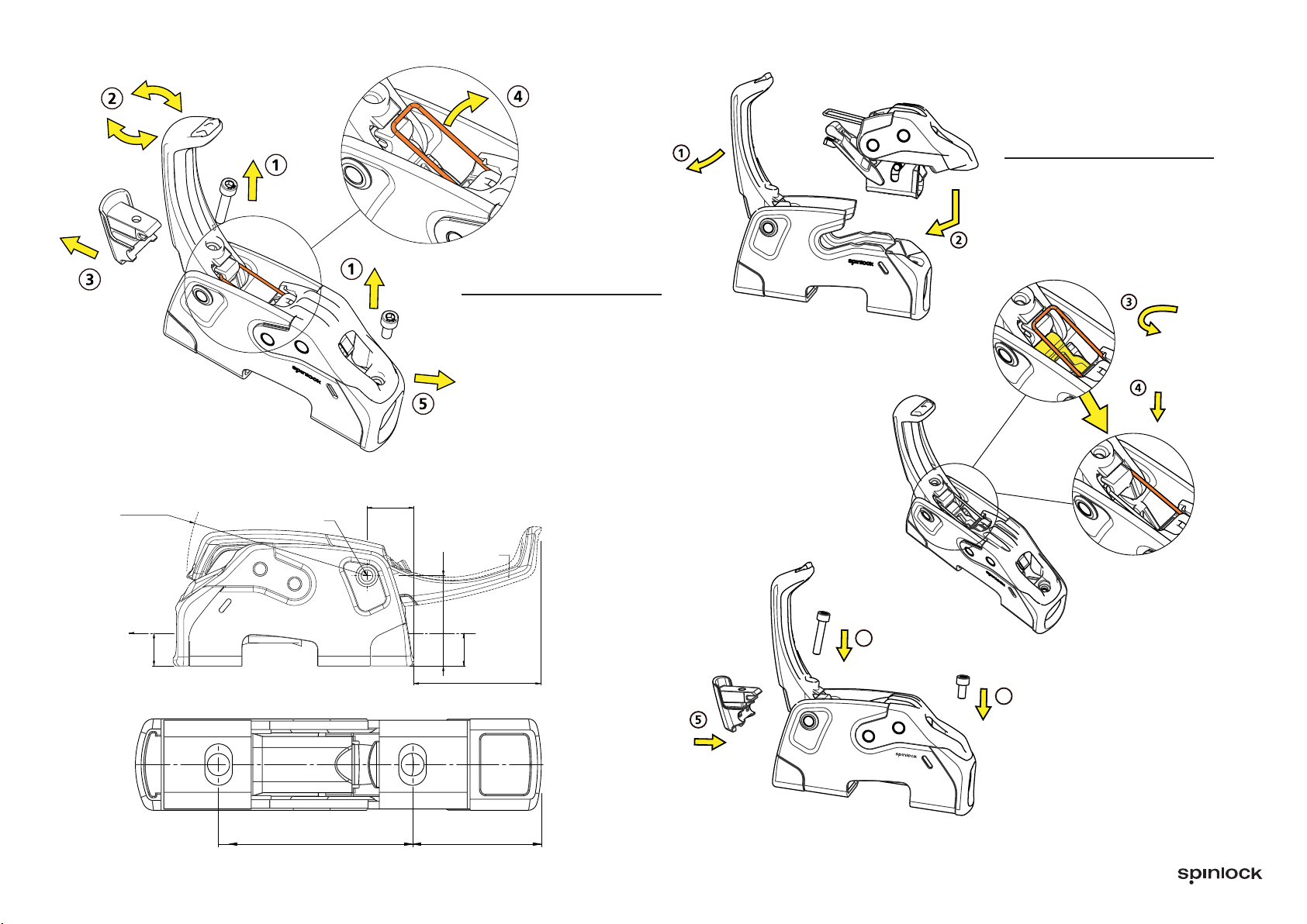
3. Hook wire loop onto handle
4. Ensure plastic link arm is
pushed down
5. Insert handle cap fully,
ensuring wire loop remains
hooked onto handle
6. Secure M5 fasteners with
4mm hex key
1. Place handle on forward axle
2. Lower grip module into body,
slide forwards in slot until fully
inserted
XTR POWERCLUTCH -
GRIP MODULE RE-ASSEMBLY
1. Remove 2 x M5 fixing with
4mm hex key
2. Twist handle slightly to
loosen handle cap
3. Remove handle cap
4. Unlock wire loop from handle
5. Slip grip module out
XTR POWERCLUTCH -
REMOVING GRIP MODULE
Table of contents
Languages:
Other Spinlock Marine Equipment manuals


