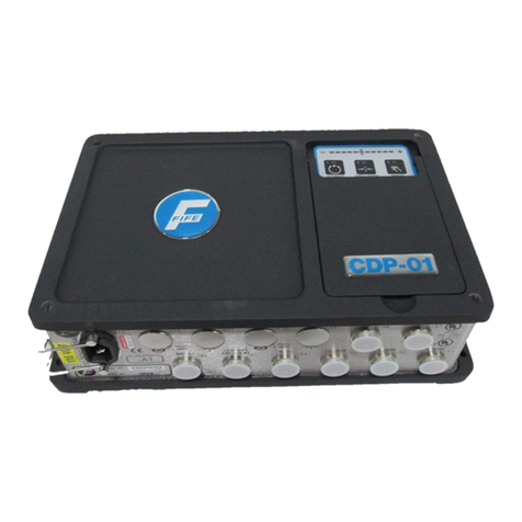
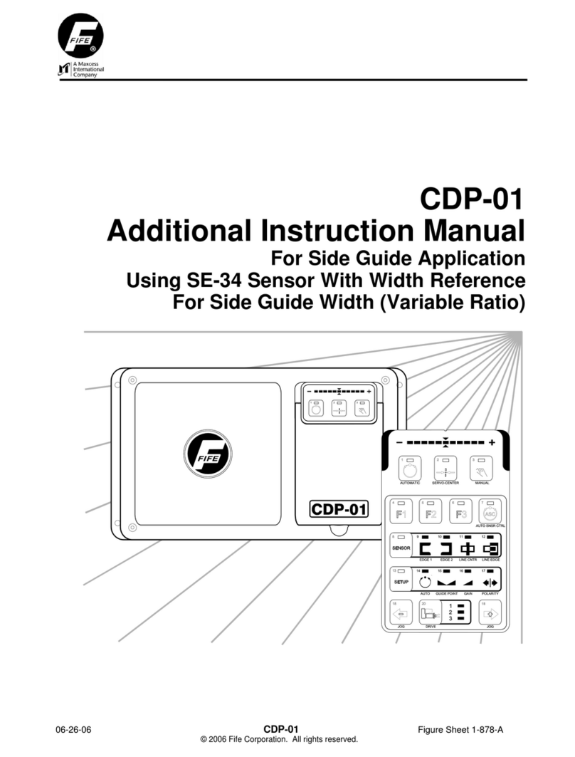
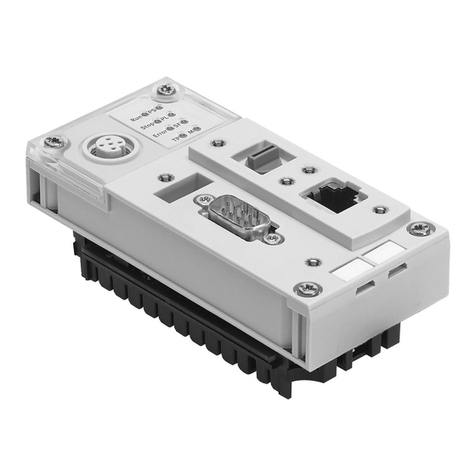
Fife CDP-01 User manual

CDP-01
Additional Instruction Manual
For Using an SBPC-2X on a Moving Sensor
Centerguide With Centerline Shift
12-14-04 CDP-01 Figure Sheet 1-879

12-14-04 CDP-01 Figure Sheet 1-879

SUPPLEMENTARY OPERATING MANUAL i
COPYRIGHT
NOTE
These additional instructions explain the special features of the system delivered to the customer. They
are intended for being used in conjunction with the CDP-01 Reference Manual. The CDP-01 Reference
Manual applies except as noted to the contrary in these instructions.
Copyright:
All rights reserved. Any reproduction of this Additional Instruction Manual, in any form, in whole or in part,
requires the prior written consent of FIFE.
The information given in this Additional Instruction Manual is subject to change without notice.
We have compiled this Additional Instruction Manual with the greatest possible care and attention:
however, the possibility of error can not be completely excluded. FIFE accepts no legal liability for
incorrect information given and the consequences arising therefrom.
Copyright 2004 FIFE Corporation, P.O. Box 26508, Oklahoma City, OK 73126, U.S.A.
FIFE GmbH,Postfach 1240, D-65762 Kelkheim/Ts., Germany
12-14-04 CDP-01 Figure Sheet 1-879

12-14-04 CDP-01 Figure Sheet 1-879

SUPPLEMENTARY OPERATING MANUAL iii
12-14-04 CDP-01 Figure Sheet 1-879
TABLE OF CONTENTS
GENERAL INTRODUCTION 1
APPLICATION DESCRIPTION............................................................................................ 1-1
SOFTWARE PART NUMBERS ........................................................................................... 1-1
CONNECTING THE SYSTEM COMPONENTS .................................................................. 1-1
SYSTEM CALIBRATION 2
CALIBRATING THE EDGE SENSORS ............................................................................... 2-1
ADJUSTING THE ENCODERS ........................................................................................... 2-1
ADJUSTING POLARITIES AND GAIN ......................................................................2-1 to 2-2
OVERVIEW OF FUNCTION 3
OPERATOR CONTROL OPTIONS ..................................................................................... 3-1
SPECIAL FEATURES OF EXTERNAL CONTROL ............................................................. 3-1
EXTERNAL CONTROL ....................................................................................................... 3-2
CONTROL MATRIX............................................................................................................. 3-3
EXPLANATION OF THE OPERATING MODES......................................................3-4 to 3-10
SENSOR SELECTION – SENSOR INDICATOR............................................................... 3-11
TROUBLESHOOTING 4
FAULT DIAGNOSIS - FAULT RECTIFICATION.................................................................. 4-1

12-14-04 CDP-01 Figure Sheet 1-879

SUPPLEMENTARY OPERATING MANUAL 1
-11
12-14-04 CDP-01 Figure Sheet 1-879
GENERAL INTRODUCTION
Application Description
The sensors are positioned manually or automatically over the edge of the web. The web is
adjusted to the position of the sensor via the rotating frame. The material web can be shifted in
edge and center guiding configurations. Internal (keypad) or External (SBPC-2X) control can be
used.
Scope of application: edge and center guiding configuration systems with moving sensors,
shifting web center point and internal or external control.
A CDP-01-MMM with FifeNet firmware is required for this application.
Software Part Numbers
The software part numbers are located on the side of the CDP-01 housing. They include the
Matrix Setup no. (MS) , State Machine no. (SM) and firmware version ( Dx ).
CDP version: CDP-01-MMM D1:565051-02x MS: 100308.02x Please quote these
D2:565052-02x SM: 100309.02x details with all inquiries.
D3:565052-02x FIFE USA
Connecting the System Components
The system components are to be connected according to the Cable Connection Diagram
contained in the documentation.

12-14-04 CDP-01 Figure Sheet 1-879

SUPPLEMENTARY OPERATING MANUAL 2
-12
12-14-04 CDP-01 Figure Sheet 1-879
SYSTEM CALIBRATION
Calibrating the Edge Sensors
The edge sensors are calibrated according to the ‘CDP-01 Reference Manual’ section 7-8
‘Sensor Calibration with Edge Sensors’ for sensors (LED 9 and LED 10).
Adjusting the Encoders
The Protrac encoders should be adjusted according to the ‘CDP-01 Reference Manual’ section
9-2 ‘Defining Displacement Limts, Limiting Stroke’ on all drives.
Adjusting Polarities and Gain
The Polarities and Gain should be adjusted according to the ‘CDP-01 Reference Manual’ section
7-16 ‘Changing the System Gain with the Web at Standstill’ and section 7-16 ‘Changing the
Guide Direction’.
The following operating modes are defined in this application.
DRIVE 1
Left edge guiding configuration.
Right edge guiding configuration.
Center guiding configuration.

SUPPLEMENTARY OPERATING MANUAL 2
2-2
DRIVE 2
Sensor Seek for Left edge and Center guiding modes.
Left edge guiding configuration.
Center guiding configuration.
DRIVE 3
Sensor Seek for Right edge and Center guiding modes.
Right edge guiding configuration.
Center guiding configuration.
12-14-04 CDP-01 Figure Sheet 1-879

SUPPLEMENTARY OPERATING MANUAL 3
-13
12-14-04 CDP-01 Figure Sheet 1-879
OVERVIEW OF FUNCTION
Operator Control Options
The CDP-01 signal amplifier can be operated by way of the CDP-01 control panel (internal
operation) or via the SBPC-2X (external operation).
The symbols below are used for the various operator control options in the following:
Internal operation
External operation
Special Features of External Control
When the operation modes are being controlled via
external control, the Automatic, Servo-Center, Manual
keys of the CDP-01 control panel are disabled.
Changing mode via external activation is only possible
when the SETUP function is deactivated on the internal
control panel.
If the External commands are sent for ‘Manual - Rotating
frame’ or ‘Manual - Sensor positioner’ modes, the drive
selector key is disabled or locked.
If the cable to the serial port ( -X8 ) of the CDP-01 is
disconnected, the CDP-01 will lock up.

SUPPLEMENTARY OPERATING MANUAL 3
3-2
External Control
The table below shows the configuration mapping for data traveling from a Network to FifeNet.
Network to FifeNet Data
Scheduled Data
Word Source1
Data Type2
Variable
Description
0 WORD Device 1
Command3
Network commands sent to the CDP-01.
Simulated key presses, etc.
1 WORD Control Matrix Used to control the CDP-01 in
accordance with the control matrix.
2 WORD SM Command Used to send special commands to the
CDP-01.
3 INT Value Value used by the SM Command
4 WORD [2] Reserved
5 WORD [3] Reserved
6 WORD [4] Reserved
1= All data words are 16 bits.
2= Data Types:
* INT 16-bit signed value in the range of –32,768 to +32,767.
* WORD 16-bit unsigned value in the range of 0 to 65,535.
3= Commands to the CDP-01.
Scheduled Data Words 2 & 3 are used to change the Guidepoint in the CDP and set the Jog
Speed. To function properly, they must be used in conjunction with each other as noted below.
●Data word 2 (SM Command) selects command. The commands are a four (4) digit Hex
number, which are sent on scheduled data word SM Command. The first two (2) digits are the
commands. The fourth digit chooses the drive. The table below explains this command using a
4 digit Hex number.
●Data word 3 (Value) controls the amount of offset and the speed of the Jogs. The range for the
Guidepoint is -32768 to +32767. Note: the guidepoint shift value is a shift amount and not a
position. The sign determines the direction. The range for the Jog Speed is 0 to +32767 with a
default value of 16383 (50%).
Calibration Commands (SM Command)
X X = Command X = Parameter 1 X = Parameter 2
0 1 = Guidepoint Shift 0 1 = Fine shift (within bandwidth of sensor)
2 = Course shift (shift sensors on the positioner)
0 8 = Jog Speed 0 1 = Drive 1
2 = Drive 2
3 = Drive 3
The recommended use is to set the Value while the SM Command is zero (0). Then select the
command with the SM Command. As soon as the CDP-01 receives the command signal, it will
immediately send the command back on scheduled Data Word 11 (SM Command Feedback) for
‘hand shaking’.
12-14-04 CDP-01 Figure Sheet 1-879

SUPPLEMENTARY OPERATING MANUAL 3
3-3
Control Matrix
COMMAND VIA NETWORK HEX
Lockout (X7 only) 01
Manual – Rotating frame 06
Manual – Sensor positioner (D2) 0A
Manual – Sensor positioner (D3) 02
Automatic 08
Servo-center 04
Auto–Lock 0C
Left – Rotating frame (D1) 16
Right – Rotating frame (D1) 26
Left – Sensor positioner (D2) 1A
Right – Sensor positioner (D2) 2A
Left – Sensor positioner (D3) 12
Right – Sensor positioner (D3) 22
Sensor Selection – Edge Right 40
Sensor Selection – Edge Left 80
Sensor Selection – Edge Center C0
12-14-04 CDP-01 Figure Sheet 1-879

SUPPLEMENTARY OPERATING MANUAL 3
3-4
Explanation of the Operating Modes
NOTE: All Start-up Procedures must be performed before Automatic and Servo
Center modes are used.
LOCKOUT
’Lockout
Set lockout.
Note: ‘LOCKOUT’ mode can only be set via the parallel port.
The rotating frame and the sensor positioner are locked.
Check: left and right LEDs of the LED bar
and LED for drive 1 flash.
Note: lockout is only effective in ‘AUTOMATIC’ mode.
MANUAL – Rotating Frame
’Manual - Rotating
frame’
Press key 3, and if necessary, the drive selector key
until the LED for drive 1 lights up or select ‘Manual-
Rotating frame’ via external control.
The sensor positioner and the rotating frame are
switched to Manual.
Check: LED (3) lit.
Setup functions can be performed and sensor modes
selected, if desired.
‘Left’
‘Right’
Press the - or + key to set ‘Left’ or ‘Right’ to manually
alter the position of the drive.
Note: with External control, ‘Left-Rotating frame’
or ‘Right-Rotating frame’ mode must be set.
12-14-04 CDP-01 Figure Sheet 1-879

SUPPLEMENTARY OPERATING MANUAL 3
3-5
MANUAL – Sensor Positioner
’Manual - Sensor
Positioner (D2)’
Press key 3, and if necessary, the drive selector key
until the LED for drive 2 lights up or select ‘Manual-
Sensor Positioner (D2)’ via external control.
The sensor positioner and the rotating frame are
switched to Manual.
Check: LED (3) lit.
Setup functions can be performed and sensor modes
selected, if desired.
‘Left’
‘Right’
Press the - or + key to set ‘Left’ or ‘Right’ to manually
alter the position of the drive.
Note: with External control, ‘Left - Sensor positioner (D2)’ or
‘Right - Sensor positioner (D2)’ mode must be set.
MANUAL – Sensor Positioner
’Manual - Sensor
Positioner (D3)’
Press key 3, and if necessary, the drive selector key
until the LED for drive 3 lights up or select ‘Manual-
Sensor Positioner (D3)’ via external control.
The sensor positioner and the rotating frame are
switched to Manual.
Check: LED (3) lit.
Setup functions can be performed and sensor modes
selected, if desired.
‘Left’
‘Right’
Press the - or + key to set ‘Left’ or ‘Right’ to manually
alter the position of the drive.
Note: with External control, ‘Left - Sensor positioner (D3)’ or
‘Right - Sensor positioner (D3)’ mode must be set.
12-14-04 CDP-01 Figure Sheet 1-879

SUPPLEMENTARY OPERATING MANUAL 3
3-6
AUTOMATIC
Select the sensor mode.
Note: only possible in the ‘Manual - Rotating frame’ or
‘Manual - Sensor positioner’ or ‘Servo-center’ modes.
Left Edge Guiding
Drive 1 – Edge Left
Drive 2 – Line Center
or
Right Edge Guiding
Drive 1 – Edge Right
Drive 3 – Line Edge
or
Center Guiding
Sensor configuration all three drives.
12-14-04 CDP-01 Figure Sheet 1-879

SUPPLEMENTARY OPERATING MANUAL 3
3-7
AUTOMATIC – Edge Guiding
’Automatic’
Press key 1 or select ‘Automatic’.
The sensor is automatically positioned over the edge of
the web.
The panel is set to drive 1.
The system adjusts the edge of the material web to the
sensor position.
Position the sensor with External control using the
Guidepoint Shift command.
The system gain (control sensitivity) of the rotating frame
can be changed.
12-14-04 CDP-01 Figure Sheet 1-879

SUPPLEMENTARY OPERATING MANUAL 3
3-8
AUTOMATIC – Center Guiding
configuration
’Automatic’
Press key 1 or select ‘Automatic’.
The sensors search for the edge of the web.
The panel is set to drive 1.
During the edge search, the rotating frame is in the
‘Automatic’ mode. The ASC function is activated.
Check: LED 7 and the two outer LEDs of the LED bar flash.
When one of the sensors finds the web, the rotating
frame is enabled and the web is slaved until the second
sensor has found the opposite edge of the web.
Note: LED 7 lights up constantly, while the outer LEDs of
the LED bar no longer flash.
The sensor positioner and the rotating frame are in the
Automatic mode. The sensors adapt to a fluctuating web
width.
If the search detects no web, or if the web tears during
guiding, the sensors reach their inner extreme position.
The system switches to ‘Servo-center’ mode.
Note: the error must be acknowledged by selecting the
‘Servo-center’ mode.
The system adjusts the edge of the material web to the
sensor position.
Position the sensor with External control using the
Guidepoint command.
The system gain (control sensitivity) of the rotating frame
can be changed.
12-14-04 CDP-01 Figure Sheet 1-879

SUPPLEMENTARY OPERATING MANUAL 3
3-9
AUTO-LOCK
’Auto-Lock’
Set Auto-Lock.
The sensors move to their parked position.
The rotating frame is switched to Manual.
The panel is set to drive 1.
AUTOMATIC – After Auto-
Lock
’Automatic’
Set Automatic.
The sensors search for the edge of the web, then move
to the same position prior to ‘Auto-Lock’.
12-14-04 CDP-01 Figure Sheet 1-879

SUPPLEMENTARY OPERATING MANUAL 3
3-10
SERVO-CENTER
’Servo - center’
Press key 2 or select Servo-center.
The sensors move to their parked position. The rotating
frame moves to the center position.
Check: LED 2 lit.
The sensor mode can be changed in this mode of
operation.
12-14-04 CDP-01 Figure Sheet 1-879
Other manuals for CDP-01
9
Table of contents
Other Fife Controllers manuals
