manuals.online logo
Brands
  1. Home
  2. •
  3. Brands
  4. •
  5. Fife
  6. •
  7. Controllers
  8. •
  9. Fife PRO-TRAC 100 User manual

Fife PRO-TRAC 100 User manual

SETUP CONFIGURATION
The configuration jumpers and switches are located
inside the control box. To access them, open the
enclosure by first removing AC power to the control
box, remove the four screws which secure the cover
plate to the bottom plate, and then remove the top.
The circuit board is attached to the top cover.
Before using this setup procedure, the following must
be determined:
1. Line Voltage: 115 or 230 VAC?
2. Type of Measurement: Web width or edge posi-
tion?
3. Jog Direction: Which direction for each of the
push buttons?
4. Units to be Displayed: Inches or millimeters?
5. Display Polarity: Directions corresponding to in-
creasing and decreasing measurements.
Refer to Figure 1 for the location of the jumpers and
switches referred to in the following procedure.
1. To configure the Pro-Trac 100 for 115 VAC or
230 VAC operation, install 16 or 18 AWG wire
jumpers on TB1 terminal block (located inside
the control box) as follows:
A. For 115 VAC operation, use one jumper on
TB1 from pin 4 to pin 5 and another jumper
on TB1 from pin 6 to pin 7.
B. For 230 VAC operation, use one jumper on
TB1 from pin 5 to pin 6.
NOTE:
Steps 2 through 5 describe the jumpers and switches
used to configure the operating parameters of the
Pro-Trac 100 control. These jumpers and switches
are located inside the control box.
Unless otherwise specified, the Pro-Trac 100 control
station will be configured at the factory as follows.:
A. Jumper JP1: “Web Width” position. Display
shows “Web Width.”
FIFE CORPORATION
Post Office Box 26508
Oklahoma City, Oklahoma 73126, U.S.A.
Phone: (405) 755-1600 Fax: (405) 755-8425
Telex: 747276 INSTALLATION INSTRUCTIONS
FIGURE 1
REV DATE 11-02-95 PRO-TRAC 100 CONTROL STATION FIG. 1-596
SETUP CONFIGURATION PAGE 1 OF 2
B. Jumper JP2: “A” position. Left jog button
moves the sensor toward the motor end.
C. Switch S1: “Inch” position. Display shows
“Inches.”
D. Switch S2: “+” position. Display increases
as sensor moves further from motor end.
See Steps 2 through 5 for explanations of these
selections.
NOTE:
To change the configuration, use Steps 2 through 5
to set the jumpers and switches to match the
installation requirements.
2. Web Width/Edge Position Select, Jumper JP1
A. If “Web Width” is to be displayed, this
jumper must be placed in the “A” position.
B. If “Web Edge Position (or Sensor Lateral Po-
sition)” is to be displayed, this jumper must
be placed in the “B” position.
3. Jog Polarity Selection, Jumper JP2
A. If it is desired to have the “Left” jog button
move the sensor toward the motor end of
the positioner and the “Right” jog button
move the sensor away from the motor end
of the positioner, this jumper must be placed
in the “A” position.
B. If it is desired to have the “Left” jog button
move the sensor away from the motor end
of the positioner and the “Right” jog button
move the sensor toward the motor end of
the positioner, this jumper must be placed in
the “B” position.
4. Inch/MM Selection, Switch S1
A. If it is desired to display web width or sensor
position in inches, this switch must be set to
the “Inch” position.
B. If it is desired to display web width or sensor
position in millimeters, this switch must be
set to the “MM” position.
5. Display Polarity Selection, Switch S2
A. If it is desired to have the display increase
as the sensor moves further from the motor
end of the positioner, this switch must be set
to the “+” position.
B. If it is desired to have the display decrease
as the sensor moves further from the motor
end of the positioner, this switch must be set
to the “-” position.
6. Enclosure Reassembly
A. Align the bottom plate with the rest of the
enclosure.
B. Insert the two longer screws (which were
previously removed) into the upper left and
lower right holes of the front panel and
thread them into the supplied nuts. Slightly
tighten these screws.
C. Insert the two shorter screws (which were
previously removed) into the other two op-
posing corner holes of the front panel and
thread them into the rear panel.
D. Tighten all four screws to seat the rubber
seals on the enclosure.
FIG. 1-596 PRO-TRAC 100 CONTROL STATION REV DATE 11-02-95
PAGE 2 OF 2 SETUP CONFIGURATION
Other Fife Controllers manuals

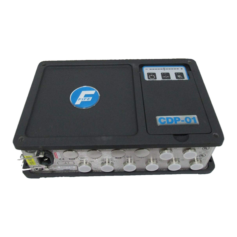
Fife CDP-01 User manual

Fife

Fife CDP-01 User manual

Fife CDP-01 User manual

Fife

Fife CDP-01 User manual

Fife CDP-01 User manual

Fife

Fife CDP-01 User manual

Fife CDP-01 User manual

Fife

Fife CDP-01 User manual

Fife CDP-01 User manual

Fife

Fife CDP-01 User manual

Fife CDP-01 User manual

Fife

Fife CDP-01 User manual

Popular Controllers manuals by other brands

THORLABS BSC103 user guide

THORLABS

THORLABS BSC103 user guide

Evco RICS 4.30 user manual

Evco

Evco RICS 4.30 user manual

Madas RG/2MC manual

Madas

Madas RG/2MC manual

Carel Easy PJEZS Series Guide

Carel

Carel Easy PJEZS Series Guide

Omron SYSMAC CJ1W-EIP21 Operation manuals

Omron

Omron SYSMAC CJ1W-EIP21 Operation manuals

Inovance Easy521 user guide

Inovance

Inovance Easy521 user guide

Omron V680-CA5D01-V2 instruction sheet

Omron

Omron V680-CA5D01-V2 instruction sheet

Siemens SIMATIC NET SCALANCE WLC711 Getting started

Siemens

Siemens SIMATIC NET SCALANCE WLC711 Getting started

TDS TSC 2000 series user manual

TDS

TDS TSC 2000 series user manual

Hama Wireless Guitar Controller operating instructions

Hama

Hama Wireless Guitar Controller operating instructions

SeaHawk LD1000 quick start guide

SeaHawk

SeaHawk LD1000 quick start guide

Flowserve Limitorque LTQ008 User instructions

Flowserve

Flowserve Limitorque LTQ008 User instructions

Karl Suss CIC 1200 manual

Karl Suss

Karl Suss CIC 1200 manual

Dometic Go Power! 30 AMP RVC MPPT user manual

Dometic

Dometic Go Power! 30 AMP RVC MPPT user manual

Parker 6K8 installation guide

Parker

Parker 6K8 installation guide

EisSound KBSOUND 60201 user manual

EisSound

EisSound KBSOUND 60201 user manual

NTN K-EGA57 instruction manual

NTN

NTN K-EGA57 instruction manual

SMC Networks LEY series operating manual

SMC Networks

SMC Networks LEY series operating manual

manuals.online logo
manuals.online logoBrands
  • About & Mission
  • Contact us
  • Privacy Policy
  • Terms and Conditions

Copyright 2025 Manuals.Online. All Rights Reserved.