Fike FlamQuench II User manual

SOLUTIONS
Fire Protection
Explosion Protection
Overpressure Protection
Pressure Activation
INSTALLATION AND MAINTENANCE INSTRUCTIONS
FlamQuench II™
VENTING WITH FLAME AND PARTICLE
RETENTION - PASSIVE EXPLOSION
PROTECTION
Doc. 8.8520.00.5
Rev. April, 2019

COPYRIGHT INFORMATION
© Copyright 2017, Fike Corporation. All rights reserved. Printed in Europe.
This document may not be reproduced, in whole or in part, by any means without the prior written consent of Fike. All
Fike documentation and hardware are copyrighted with all rights reserved.
TRADEMARKS
Fikeis a registered trademark of Fike. All other trademarks, trade names or company names referenced herein are
the property of their respective owners.
ERRORS AND OMISSIONS
While every precaution has been taken during the preparation of this document to ensure the accuracy of its content,
Fike assumes no responsibility whatsoever for errors or omissions.
Fike reserves the right to change product designs or specifications without obligation and without further notice in
accordance with our policy of continuing product and system improvement.
READER QUESTIONS AND RESPONSES
If you have any questions regarding the information contained in this document, or if you have any other enquiries
regarding Fike products, please call Fike Europe Product Support at 0032 14 21 00 31.
Fike encourages input from our distributors and end users on how we can improve this manual and even the product
itself. Please direct all calls of this nature to Fike Europe Product Support at 0032 14 21 00 31. Any communication
received becomes the property of Fike.
TERMS AND CONDITIONS OF SALE
Because of the many and varied circumstances and extreme conditions under which Fike’s products are used, and
because Fike has no control over this actual use, Fike makes no warranties based on the contents of this document.
FIKE MAKES NO IMPLIED WARRANTIES OF MERCHANTABILITY OR FITNESS FOR A SPECIFIC PURPOSE. Refer to
www.fike.com/terms-conditions for Fike’s full TERMS AND CONDITIONS OF SALE.
TERMS OF USE
Do not alter, modify, copy, or otherwise misappropriate any Fike product, whether in whole or in part. Fike assumes
no responsibility for any losses incurred by you or third parties arising from such alteration, modification, copy or
otherwise misappropriation of Fike products.
Do not use any Fike products for any application for which it is not intended. Fike shall not be in any way liable for any
damages or losses incurred by you or third parties arising from the use of any Fike product for which the product is not
intended by Fike.
You should install and use the Fike products described in this document within the range specified by Fike, especially
with respect to the product application, maximum ratings, operating supply voltage range, installation and other
product characteristics. Fike shall have no liability for malfunctions or damages arising out of the use of Fike products
beyond such specified ranges.
You should install and use the Fike products described in this document in compliance with all applicable laws,
standards, and regulations in the country of installation. Fike assumes no liability for damages or losses occurring as a
result of your noncompliance with regionally applicable laws and regulations.
It is the responsibility of the buyer or distributor of Fike products, who distributes, disposes of, or otherwise places the
product with a third party, to notify such third party in advance of the contents and conditions set forth in this
document. Fike assumes no responsibility for any losses incurred by you or third parties as a result of unauthorised
use of Fike products.
QUALITY NOTICE
Fike has maintained ISO 9001 certification since 1996. Prior to shipment, we thoroughly test our products and review
our documentation to assure the highest quality in all respects.

Doc. P/N 8.8520.00.5
Rev. April, 2019
PAGE / 1
REVISION HISTORY
ORIGINAL RELEASE DATE: ..........................................................................................................................................June, 2017
REVISION /DESCRIPTION OF CHANGE REVISION DATE
4 / Change 5m hearing protection to 10 X D hearing protection January 2018

PAGE / 2
Doc. P/N 8.8520.00.5
Rev. April, 2019
TABLE OF CONTENTS
Section Page No.
1. INTRODUCTION ...........................................................................................................................................................3
2. GENERAL INFORMATION.............................................................................................................................................3
2.1. Description.........................................................................................................................................................3
2.2. Service Qualifications.........................................................................................................................................3
2.3. External Effects ..................................................................................................................................................3
2.4. FlamQuench II Safety .........................................................................................................................................4
2.5. FlamQuench Installation Procedure ..................................................................................................................4
2.6. FlamQuench Removal Procedure ......................................................................................................................5
2.7. Identification of FlamQuench II .........................................................................................................................5
3. INSTALLATION .............................................................................................................................................................5
4. SUPPORT CONSIDERATIONS........................................................................................................................................6
5. REFURBISHMENT INSTRUCTIONS................................................................................................................................6
5.1. Filter Handling Warning.....................................................................................................................................6
5.2. Filter Replacement.............................................................................................................................................6
5.2.1. Remove Filter (fig. 4 & 5)...............................................................................................................................6
5.2.2. Installation of Filter(s) (fig. 6) ........................................................................................................................6
5.3. Refurbish Kits.....................................................................................................................................................7
5.4. Tools Needed for Refurbishment (not included as part of kit)..........................................................................7
6. SCHEDULED MAINTENANCE........................................................................................................................................8
6.1. Every Three (3) Months .....................................................................................................................................8
7. MAINTENANCE AFTER EACH FLAMQUENCH II ACTIVATION .......................................................................................8
8. EXPLOSION VENT REQUIREMENTS..............................................................................................................................8

Doc. P/N 8.8520.00.5
Rev. April, 2019
PAGE / 3
1. INTRODUCTION
This document is intended to provide information to assist with the installation, use, maintenance and replacement of
the Fike FlamQuench II.
Fike Corporation has designed and manufactures the FlamQuench II in two versions: an imperial size unit specified
according to NA standards, available in size 8” through 40”; and a metric version specified and built for the CE market,
available in size DN200 through DN1000.
2. GENERAL INFORMATION
2.1. Description
The Fike FlamQuench II is designed to allow for indoor explosion venting with flame arresting and particulate
retention. It consists of various layers of high temperature stainless steel that retain burned and unburned dust and
absorb heat produced during the explosion.
2.2. Service Qualifications
The information contained in this document is provided for reference purposes only. For further product information
or ordering replacement parts, please contact your local Fike Branch Office or Representative (details of which can be
found on the back page) or:
Fike Product Support by calling 816-229-3405 (fax: 816-229-0314) or
Fike Europe Product Support at +32 14 21 00 31 (fax: +32 14 21 07 43)
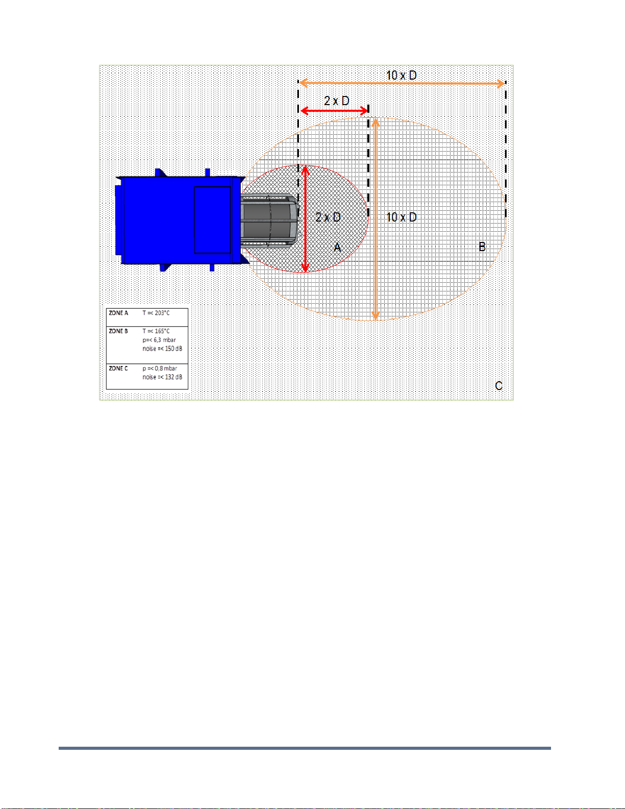
2.3. External Effects
Tests conducted with FlamQuench devices indicated that
Maximum surface temperature at the flame arrestor mesh was 203°C.
a manikin located at 1 m from the device was not blown over and no visual burn damage to polypropylene
coverall (melting point 160- 165°C).
External noise measurements at 1 m and 5 m from the device resulted peak SPL 150 dB at 1 m and at 5 m
peak SPL 132 dB.
a dust cover slightly increased to noise levels but did not increase the Pred.
External pressures –at 1m and 5 m from the device resulted in peak values of 6.3 mbar and 0.8 mbar
respectively.
Refer to figure below for guidance on safety perimeter surrounding the flameless venting device.
PAGE / 4
Doc. P/N 8.8520.00.5
Rev. April, 2019
The FQ devices reduce the noise level compared to an open vent by ~10 dB(A). Fike recommends that the user
provide appropriate hearing protection for workers who may be in the vicinity (within 10 x D) of the vent device. Local
regulations may prevail.
2.4. FlamQuench II Safety
WARNING: Any damage to the Filter may cause the FlamQuench II to malfunction, which may result in a dust
explosion in the surrounding area.
2.5. FlamQuench Installation Procedure
WARNING: When installing do not damage filter. Any damage to filter may compromise the function of the
FlamQuench II.
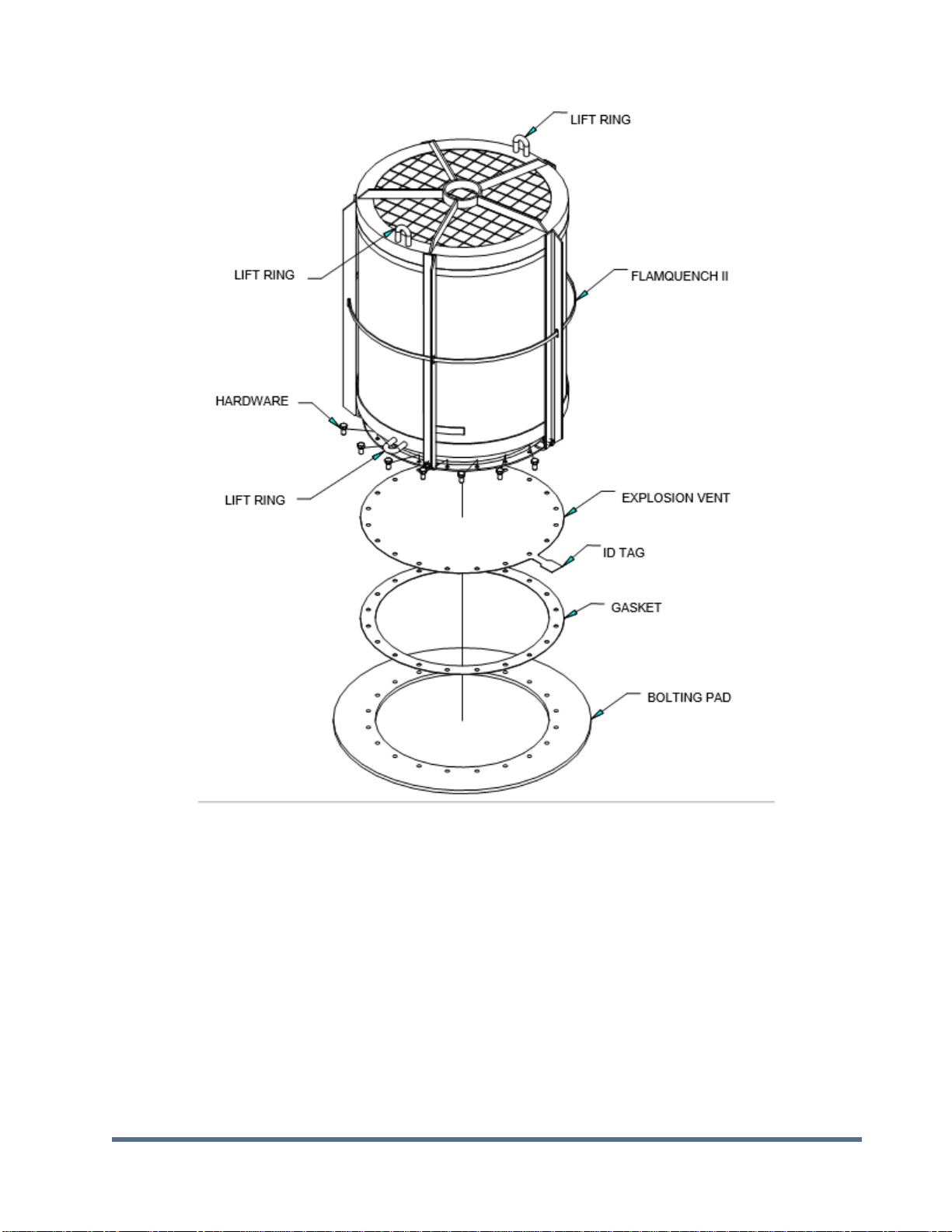
Refer to Figure 1 (page 9) for assembly diagram.
1. All system components shall be installed and the electrical and control systems thoroughly checked by a
qualified technician before proceeding with installation.
2. Use provided lift ring(s) when installing FlamQuench II. The rings are located on the top and bottom
weldments. Do not attempt to lift FlamQuench II by any other method.
3. Carefully clean gasket, explosion vent, and bolting pad surface (frame or flangering).

Doc. P/N 8.8520.00.5
Rev. April, 2019
PAGE / 5
4. Place gasket onto bolting pad (AFM30/34 or similar is the recommended gasket material. Sealant may be
used, type may vary depending on process requirements). Be sure to line up holes.
5. Place the explosion vent onto gasket with ID tag lettering facing up. Align holes.
Note: Explosion vent may be placed onto the FlamQuench II first. However you must wait until the sealant has dried
before continuing the installation. Follow the instructions on sealant for drying time.
WARNING: TAKE EXTREME CAUTION NOT TO DAMAGE EXPLOSION VENT WHEN INSTALLING FlamQuench II.
DAMAGE TO THE EXPLOSION VENT WILL CAUSE IT TO MALFUNCTION.
6. Carefully place FlamQuench II on top of explosion vent making sure holes are lined up before placing all the
weight on the explosion vent.
7. Fasten the FlamQuench II to the bolting pad using either 18-8 or 304 stainless steel hardware. Torque to 35-
40 foot pounds (48-54 N-m).
8. Connect Burst Indicator. (See Installation Instructions on connecting BI)
Note: Cables attached to lifting rings can be used to help support the FlamQuench II. Do not attempt to support the
FlamQuench II using any other method other than the lift rings
2.6. FlamQuench Removal Procedure
Caution: Before removing FlamQuench II, carefully check the surface temperature. Make sure it is not too hot to
handle.
Do not disassemble the FlamQuench II when mounted to a vessel.
1. Shut down process if not already shut down.
2. Remove hardware holding FlamQuench II to vessel.
3. Use only the provided lift rings for lifting.
4. Follow instructions in Section 5 for refurbishment.
2.7. Identification of FlamQuench II
For the purpose of identifying the FlamQuench II and ordering replacement parts and refurbishment kits the
FlamQuench II has been permanently tagged. The FlamQuench II has separate ID tags for each component. See
Figures 4 & 5 for ID tag locations. The ID tags contain the following information: Size, Part Number and Lot Number.
The explosion vent will be marked separately.
3. INSTALLATION
Keep a minimum distance of 2 feet (0.7 meters) between the FlamQuench II and any equipment or walls to
allow for proper venting.
FlamQuench II may be installed anywhere between vertical and horizontal. See Figure 2. Fike Corporation
shall evaluate any deviation from this orientation.

PAGE / 6
Doc. P/N 8.8520.00.5
Rev. April, 2019
The FlamQuench II requires sufficient support based on the FlamQuench II weight and reaction force created
during activation. Refer to Table 2 or Table 3 and Figure 3 for FlamQuench II physical specifications.
4. SUPPORT CONSIDERATIONS
The FlamQuench II should be supported to prevent damage to the vessel it is protecting. If the vessel is sufficiently
sturdy, the flange connection may be used to support the FlamQuench II. Weight and angle must be considered when
evaluating vessel strength for mounting. If the vessel wall is not sufficient to support the FlamQuench II, additional
reinforcement should be provided.
Where lighter weight vessels are used, the FlamQuench II should be supported independently. This may be
accomplished by attaching cables to the lifting rings on the top and side of the FlamQuench II.Refer to Figure 2.
5. REFURBISHMENT INSTRUCTIONS
5.1. Filter Handling Warning
WARNING: To prevent possible injury (cuts & scrapes), wear leather gloves when handling the filters.
5.2. Filter Replacement
5.2.1. Remove Filter (fig. 4 & 5)
1. Follow removal procedures in Section 2.6.
2. Remove nuts, bolts and washers and discard.
3. Use supplied lift rings to remove Top Frame Weldment. Be sure to remove lower bands on larger
FlamQuench II.
4. Remove Top and Side Filters and dispose of properly.
5. Remove Fiber Frax rings and discard in a safe manner.
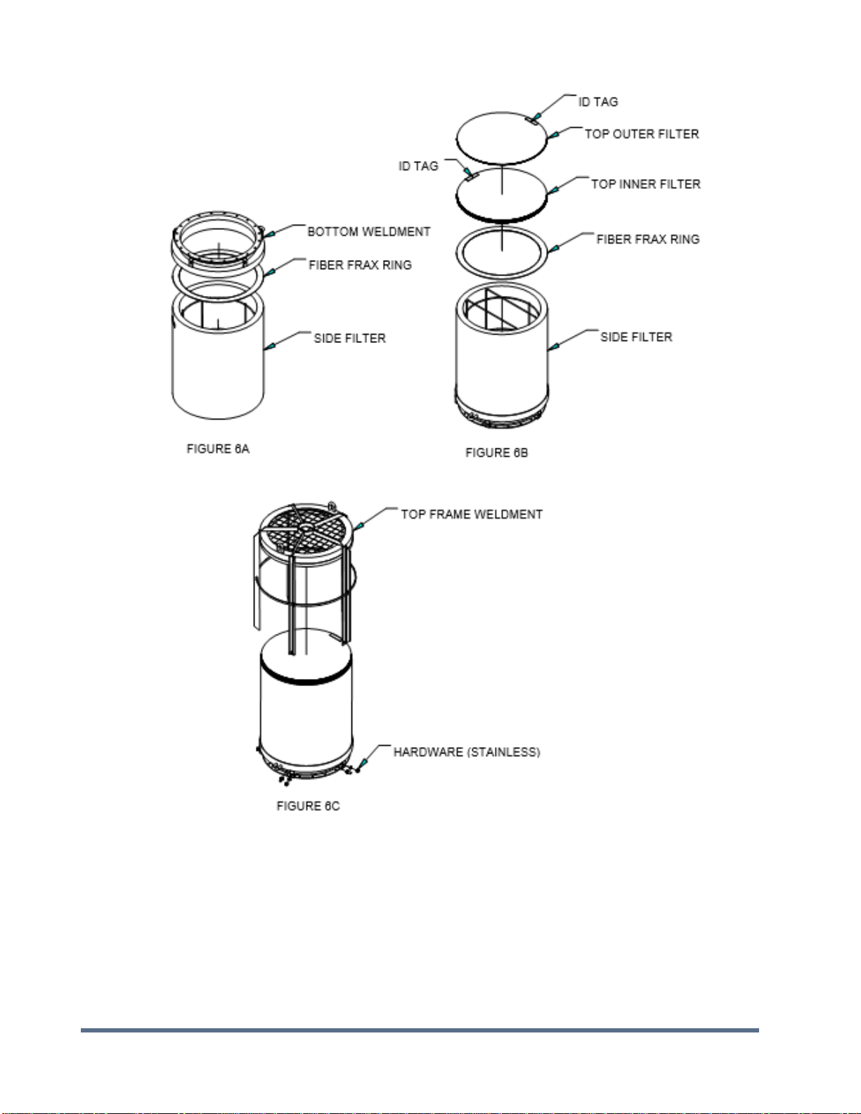
5.2.2. Installation of Filter(s) (fig. 6)
CAUTION: BEFORE INSTALLING NEW FILTER, THOUROUGLY INSPECT FRAME FOR STRESS FRACTURES. IF FRACTURES
ARE FOUND, REPLACE ENTIRE FRAME.
1. Place Fiber Frax ring into Bottom Weldment. Be careful not to tear ring.
2. Carefully install Side Filter into Bottom Weldment, ID tag down. If Filter is damaged in any way, it may
compromise the function of the filter. For easier installation turn assembly upside down to install filter. See
Figure 6A. Be sure to note location of ID tag (Refer to Figure 4 or 5).
3. Place Fiber Frax ring on top of Side Filter. See Figure 6B.
4. FlamQuench II sizes 8” – 20” (DN200 – DN500) skip to Step 9.
5. FlamQuench II sizes 24” – 40” (DN600 – DN1000) install Center Ring Support Weldment. (Refer to Figure 5)
6. Place Fiber Frax ring on top of Center Ring Support Weldment.

Doc. P/N 8.8520.00.5
Rev. April, 2019
PAGE / 7
7. Carefully install Side Filter into Center Ring Support Weldment
8. Place Fiber Frax ring on top of Side Filter.
9. Lay the Inner Top Filter on top of the Fiber Frax (ID tag up). Be sure to center this part on top of the Filter.
See Figure 6B. Be sure to note location of ID tag.
10. Lay the Outer Top Filter on top of the Inner Top Filter (ID tag up). Be sure to center. See Figure 6B . Be sure to
note location of ID tag.
11. Carefully lower Top Frame Weldment onto filter assembly. Align holes in top weldment with holes in bottom
weldment. In order to line-up holes the assembly needs to be compressed using 3 bar clamps. Place the bar
clamps equaly spaced around the diameter. Slowly tighten each bar clamp until the holes line-up. See Figure
6C .
12. Install new hardware provided. DO NOT USE OLD HARDWARE! Torque all hardware to 35 ft-lbs (48 N-m).
13. Refurbishment complete. Refer to Section 2.5 for installation.
5.3. Refurbish Kits
Each Refurbish Kit contains the following components:
Hardware (nuts, bolts, washers)
Top Inner Filter
Top Outer Filter
Side Filter (s)
Fiber Frax Rings
FlamQuench II Installation and Operation Manual (E06-045)
Table 1 - Refurbish Kits
FlamQuench II Size
Kit Part Number –English
Kit Part Number –Metric
8” (DN200)
E85-039-08
91002020-S
12” (DN300)
E85-039-12
91002120-S
14” (DN350)
E85-039-14
91002220-S
16” (DN400)
E85-039-16
91002320-S
20” (DN500)
E85-039-20
91002420-S
24” (DN600)
E85-039-24
91002520-S 2
30” (DN750)
E85-039-30
91002620-S 2
DN800
Not Available
91002720-S 1 2
36” (DN900)
E85-039-36
91002720-S 1 2
40” (DN1000)
E85-039-40
91002820-S 2
Note 1: DN800 and DN900 FlamQuench II both use the same filter elements.
5.4. Tools Needed for Refurbishment (not included as part of kit)

PAGE / 8
Doc. P/N 8.8520.00.5
Rev. April, 2019
Torque wrench
Bar clamps
p/n 91009000: bar clamps for FQII reload kit DN 200 to DN600
p/n 91009100: bar clamps for FQII reload kit DN750 to DN1000
6. SCHEDULED MAINTENANCE
All system components should be thoroughly inspected by factory trained personnel. Following are specific
requirements. Additional maintenance may be required depending on process and environmental conditions.
6.1. Every Three (3) Months
Visually inspect the system.
Keep filter free of dust. Use soft brush or vacuum to remove dust from filter.
Check for loose hardware.
The explosion vent is maintenance free.
7. MAINTENANCE AFTER EACH FLAMQUENCH II ACTIVATION
Replacement is required after every activation. This includes replacing filters and hardware (See Section 5).
8. EXPLOSION VENT REQUIREMENTS
The following round Explosion Vents have been approved for use in conjunction with the FlamQuench II.
HI-CV
HI-CV-S
Burst Indicators are required on all explosion vents when used with a FlamQuench II.

Doc. P/N 8.8520.00.5
Rev. April, 2019
PAGE / 9
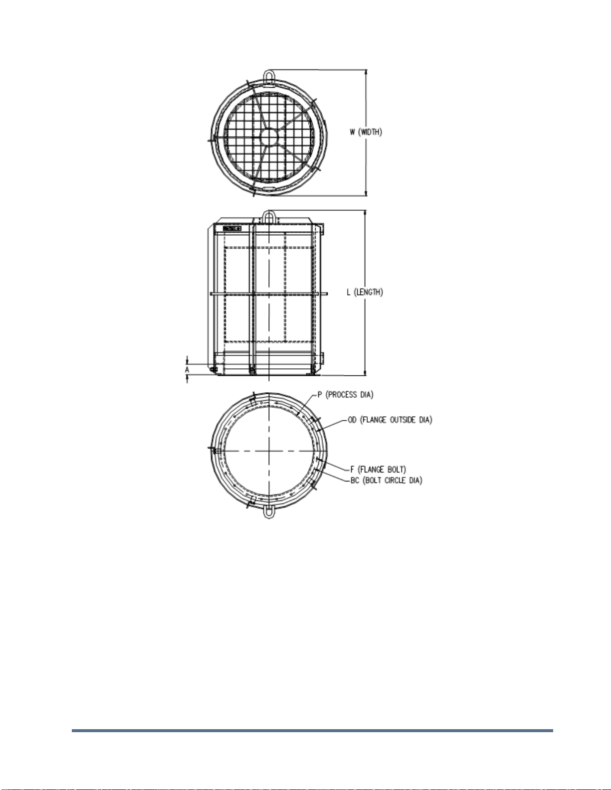
Table 2 - FlamQuench II (fig. 3)
FQ II
SIZE
P
OD
BC
F
BOLT
QTY
TORQUE
(FT-LBS.)
8”
8 1/8
10 5/8
9 ½
3/8
8
30
12”
12 3/16
15 3/16
13 13/16
7/16
12
30
14”
14 3/16
17 3/16
15 13/16
7/16
12
30
16”
16 ¼
19 ¼
18 1/8
7/16
16
30
20”
20 ¼
23 ¼
22 1/8
7/16
20
30
24”
24 ¼
27 ¼
26 1/8
7/16
20
30
30”
30 ¼
34 ¼
32 ½
9/16
28
50
36”
26 ¼
40 ¼
38 ½
9/16
32
50
40”
40 ¼
44 ¼
42 ½
9/16
36
50
NOTE: Flange stud torque values are based on using 1/8" Garlock 3600 gasket material and lightly oiled and freely
running threads.
FQ II
SIZE
L
W
A
WT
LBS.
GASKET
INSIDE DIA
GASKET
OUTSIDE DIA
8”
23 ½
13
1 ¾
44
8 1/8
10 5/8
12”
26 ¼
19
1 ¾
80
12 3/16
15 3/16
14”
31 ½
22 ¼
2 ½
113
14 3/16
17 3/16
16”
35 ½
25
2 ½
168
16 ¼
19 ¼
20”
37 ½
28 ½
2 ½
199
20 ¼
23 ¼
24”
57 ¾
32 ½
2 ½
402
24 ¼
27 ¼
30”
86 ¼
38 ¾
2 ½
635
30 ¼
34 ¼
36”
88 ¼
46 ¼
2 ½
804
26 ¼
40 ¼
40”
88 ¼
49 ¾
2 ½
965
40 ¼
44 ¼
NOTE: All specifications are subject to change and should be used for reference only.

PAGE / 10
Doc. P/N 8.8520.00.5
Rev. April, 2019
FQ II
SIZE
P
OD
BC
F
BOLT
QTY
TORQUE
(N-m)
DN200
208
268
242
10
8
40
Dn300
310
390
355
12
12
33/80**
DN350
342
422
387
12
12
33/80**
DN400
393
483
443
12
16
33/80**
DN500
494
584
544
12
20
33/80**
DN600
596
686
646
12
20
33/80**
DN750
743
843
798
12
28
33/80**
DN800
799
899
854
12
28
33/80**
DN900
900
1000
935
12
32
33/80**
DN1000
1002
1102
1057
12
36
33/80**
NOTE: Flange stud torque values are based on using 1/8" Garlock 3600 gasket material and lightly oiled and freely
running threads.
** For burst pressures less or equal to 100 mbar at 22°C. Use 33 N-m, otherwise 80 N-m.
FQ II
SIZE
L
W
A
WT
KG.
GASKET
INSIDE DIA
GASKET
OUTSIDE DIA
DN200
597
330
44
20
208
268
Dn300
664
485
44
36
310
390
DN350
800
564
63
51
342
422
DN400
900
636
63
76
393
483
DN500
954
727
63
90
494
584
DN600
1465
828
63
182
596
686
DN750
2189
982
63
288
743
843
DN800
2238
1173
63
365
799
899
DN900
2238
1173
63
365
900
1000
DN1000
2242
1264
63
438
1002
1102
NOTE: All specifications are subject to change and should be used for reference only.
Doc. P/N 8.8520.00.5
Rev. April, 2019
PAGE / 11
Figure 1- Installation Diagram

PAGE / 12
Doc. P/N 8.8520.00.5
Rev. April, 2019
Figure 2 - Installation Orientation
Doc. P/N 8.8520.00.5
Rev. April, 2019
PAGE / 13
Figure 3 - FQ II Specification 8" - 40" (DN200 - DN1000) sizes
Ref. table 2 and 3

PAGE / 14
Doc. P/N 8.8520.00.5
Rev. April, 2019
Figure 4 - FQ II Assembly 8" - 20" (DN200 - DN500)

Doc. P/N 8.8520.00.5
Rev. April, 2019
PAGE / 15
Figure 5 - FQ II Assembly 24" - 40" (DN600 - DN1000)
PAGE / 16
Doc. P/N 8.8520.00.5
Rev. April, 2019
Figure 6 - Filter Installation

Notes:

CONTACT US
Fike Europe
Toekomstlaan 52
2200 Herentals, België
Tel: +32 14 210031
www.Fike.com
For a list of contact information for Fike offices around the
world, visit the Global Locations section of Fike.com
Table of contents
Other Fike Protection Device manuals

Popular Protection Device manuals by other brands


Stahl
Stahl Series 9160 operating instructions

Segen Solar
Segen Solar ACDB-250A-2000A-8-1-1 installation manual

Kindermann
Kindermann 4003 000 001 DSH42 Mounting instructions

ABB
ABB Relion 670 series Product guide

Ametek
Ametek Surgex SA Series User manual & installation guide

Microelettrica Scientifica
Microelettrica Scientifica MC2-30M Operation manual