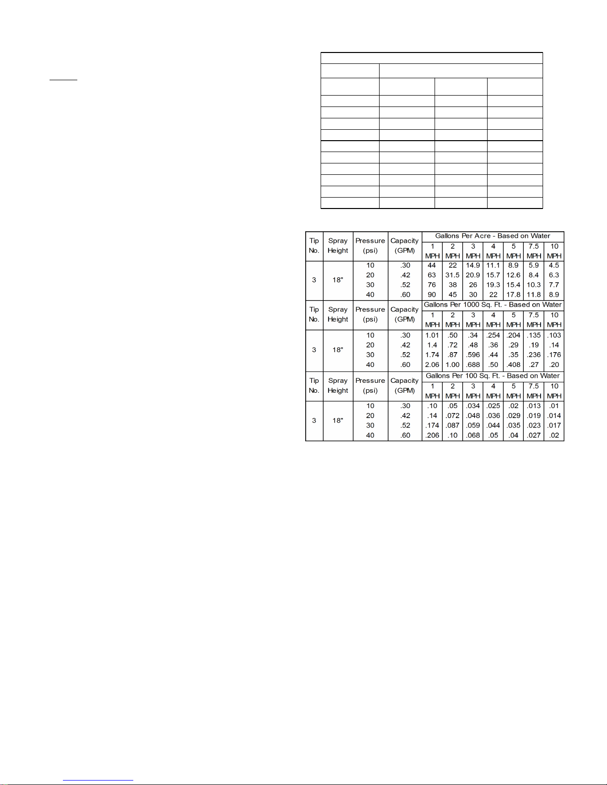
Fimco LG-1500 User manual

*** IMPORTANT REMINDER ***
A
"ON/OFF" Valve
Inlet from Tank
Detail A
This unit comes with an On/Off valve, located near
You must make sure the valve is in the
the inlet of the tank, towards the underside. (See Detail A)
"open" position before using your unit.
15 Gal. Corrosion-Resistant Polyethylene Tank
•
12 Volt Diaphragm Pump, 2.1 g.p.m. - 60 p.s.i.
•
Low Profile Trailer & Tank
•
4.10/3.50 x 4 Pneumatic Tires
•
Pressure Gauge
•
Adjustable Pressure
•
2-Nozzle Boom Assembly, 80" Coverage
•
Technical Specifications
Assembly
Model: LG-1500 (5301140)
Owner's Manual
(15 Gallon Lawn & Garden Trailer Sprayer)
Your sprayer has been partially assembled at the factory. Follow
the instructions below to complete the assembly of this unit.
(Refer to the exploded view drawing later in this manual)
1. Bolt the hitch brackets, both formed and flat, to the trailer
frame.
2. Slide the axle through the frame holes, centering it as best as
possible.
3. Slide a wheel spacer and a wheel (valve stem out) onto each
end of the axle, then use a cotter pin to secure the wheels in
place.
4. Bolt the boom brackets to the back of the frame.
5. Bolt the boom assembly to the boom brackets with the tips of
the boom facing rearward. The tips need to be approximately
18" above the spraying surface. Secure in place with (2) bolts
and nuts provided.
6. Thread the pressure gauge into the end of the manifold
assembly. Use a good grade of thread sealant, to insure no
leaks.
7. Remove the drain plug and handgun clips from the parts bag
and attach them to the tank, as shown.
8. Attach the 'loose' boom feeder hose to the center hose barb
on the manifold assembly and to the nylon feeder "tee" on the
boom. Secure in place with 1/2" hose clamps.
9. Connect the electrical hook-up to the end of your pump and
clip the clips to a fully charged battery. The red wire must be
connected to the positive (+), and the black wire should be
connected to the negative (-).
Form No. 1309 [5004803 (03/10)] Printed in the U.S.A.
General Information
Thank you for purchasing this product. The purpose of this
manual is to assist you in operating and maintaining your
lawn & garden trailer sprayer. Please read it carefully, as it
furnishes information which will help you achieve years of
trouble-free operation.
Warranty/Parts/Service
Products are warranted for one year from date of purchase
against manufacturer or workmanship defects.
Commercial users have a 90 day warranty.
Your authorized dealer is the best source of replacement parts
and service. To obtain prompt, efficient service, always
remember to give the following information...
- Correct Part Description and/or part number.
- Model number/Serial number of your sprayer.
Part descriptions and part numbers can be obtained from the
illustrated parts list section(s) of this manual.
Whenever you need parts or repair service, contact your
distributor/dealer first. For warranty work, always take your
original sales slip, or other evidence of purchase date, to your
distributor/dealer.
1000 FIMCO Lane, P.O. Box 1700, North Sioux City, SD 57049
Toll Free Phone: 800-831-0027 : Toll Free Fax: 800-494-0440
www.fimcoindustries.com

Calibration
Chemical labels may show application rates in gallons per
acre, gallons per 1000 square feet, or gallons per 100 square
feet. You will note that the tip chart shows all 3 of these rating
systems.
Once you know how much you are going to spray, then
determine (from the tip chart) the spraying pressure (PSI), and
the spraying speed (MPH).
Determining the proper speed of the pulling vehicle can be
done by marking off 100, 200, & 300 feet. The speed chart
indicates the number of seconds it takes to travel the
distances. Set the throttle and with a running start, travel the
distances. Adjust the throttle until you travel the distances in
the number of seconds indicated by the speed chart. Once
you have reached the throttle setting needed, mark the throttle
location so you can stop and go again, returning to the same
speed.
Add water and proper amount of chemical to the tank and
drive to the starting place for spraying.
Testing the Sprayer
NOTE:
It is VERY important for you to test your sprayer with
plain water before actual spraying is attempted. This will
enable you to check the sprayer for leaks, without the
possibility of losing any expensive chemicals.
Add water to the tank & drive to the starting place for
spraying. When you are ready to spray, turn the boom valve
to the "on" position. This will start solution spraying from the
tips of the boom. The pressure will decrease slightly when the
boom is spraying. Adjust the pressure by turning the
"ON/OFF" valve lever on the bypass line valve.
Read the operating instructions and Initially begin spraying by
closing the 'bypass' valve (this is the center ON/OFF valve
located at the center port of your manifold assembly) and
opening the boom line valve (this is the 'other' valve on the
manifold). This will enable the air in the line to be eliminated
(purged) through all the tips, while building pressure. When
everything tests all right (no leaks, & good pressure), add the
desired chemicals to the mixture and water combination and
start your spraying operation. Adjust the pressure and spray
as you did in the testing procedure.
Conditions of weather and terrain must be considered when
setting the sprayer. Do not spray on windy days. Protective
clothing must be worn in some cases.
Be sure to read the chemical label(s) correctly!
WARNING:
Some chemicals will damage the pump valves if
allowed to soak untreated for a length of time! ALWAYS
thoroughly flush the pump with water after use. DO NOT
allow chemicals to sit in the pump for extended times of
idleness. Follow the chemical manufacturer's instructions on
disposal of all waste water from the sprayer.
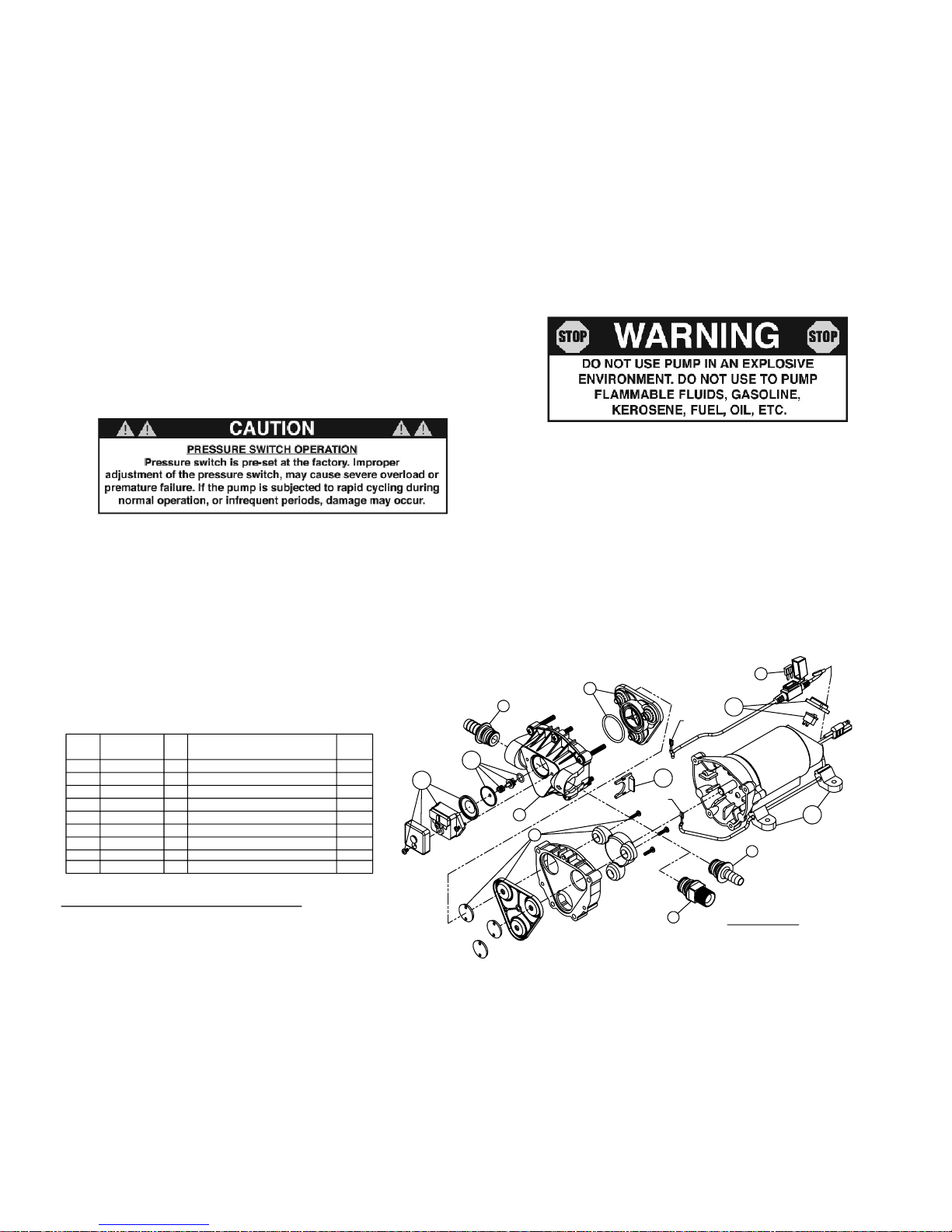
Operation
Your sprayer is equipped with (2) ON/OFF switches. One is
on the wire assembly that you hook up to your battery, the
other is on the pump itself, on the opposite end of the
pressure switch. The "-" is the "ON" position and the "o" is
the "OFF" position for the switches. Make sure both switches
are depressed in the "-" position for operation.
In addition to the ON/OFF switch, the pump is equipped with
an electronic pressure switch that is factory pre-set for it to
shut off at 60 p.s.i.. This switch assembly is the 'square box'
on the head portion of the pump.
Always fill the tank with a desired amount of water first, and
then add the chemical slowly, mixing as you pour the
chemical into the tank. You may use the handgun to spray
into the solution in order to mix the chemical and water.
The pumping system draws solution from the tank, through
the strainer/filter, and to the pump. The pump forces the
solution under pressure to the handgun and/or boom
nozzles.
Open the handgun by squeezing the handle lever.
•
Rotating the adjustable nozzle tip on the handgun will
•
change the tip pattern from a straight stream to a cone
pattern (finer mist).
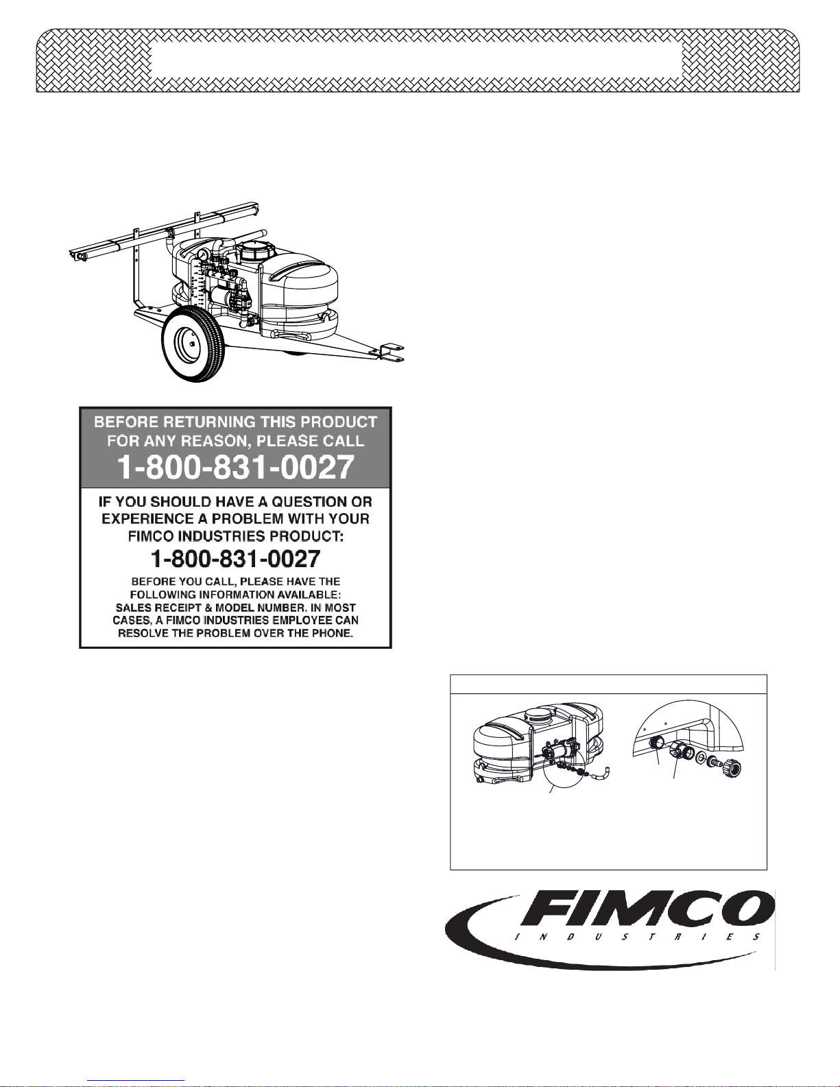
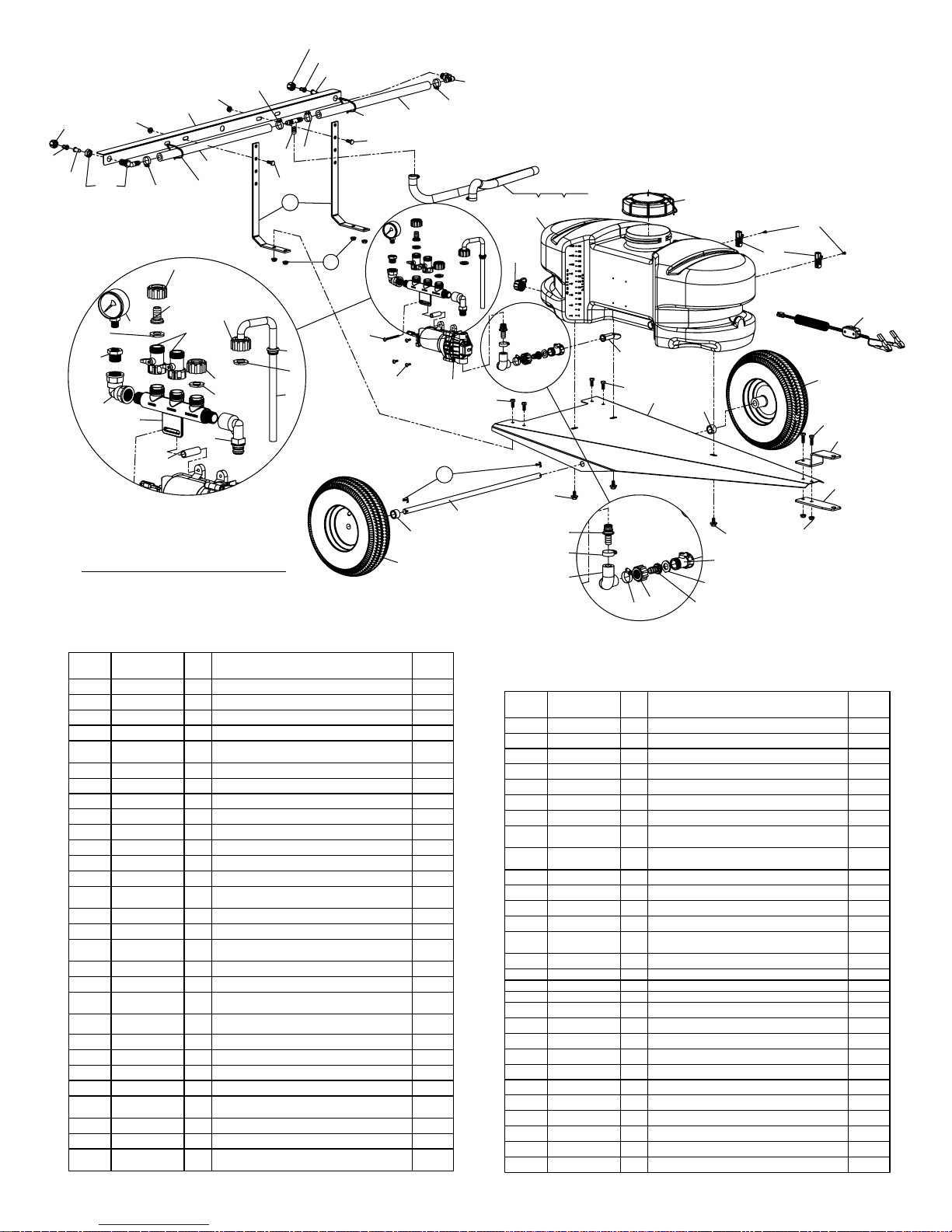
This sprayer is designed to be towed behind a garden
tractor.
The nozzles on the boom will spray an 80 inch wide swath.
Check the nozzle pattern by spraying water on a concrete
surface. Raise the boom to a higher mounting position to get
more spray pattern overlap, if desired.
Time Required in seconds to travel a distance of:
17 34
4.0
5.0
6.0
7.0
9.0
8.0
10.0
7.6
6.8
9.7
8.5
14
11
15
14
19
17
23
27
100 Ft.
68 sec.
2.0
3.0
1.0
(Miles per Hour)
Speed in M.P.H.
Speed Chart
136 sec.
34
23 45
68
200 Ft.
51
23
20
26
29
41
34
205 sec.
300 Ft.
102
68
Page 2

3.3
If none of the above will work, try pulling wire terminal "A" off of the spade terminal of the pressure switch, and cross it over and touch terminal "B". (You will need to
remove the pressure switch cap before doing this) If your pump runs when you do this, you know you will need to replace your pressure switch.
Another thing you can try is to take apart the switch box on the lead wire assembly (#5274443) with the (2) phillips head screws, and 'hot-wire' it together. Take the
(2) wires that are screwed to the rocker switch, off of the switch and twist them together. This will insure you are getting the full 12 volts to the pump. If your pump
- Check line strainer (screen) at the inlet location, at the tank. You will need to unscrew the knurled nut to access this screen. (see exploded view later in this manual)
The ON/OFF valve should be closed while performing this, to insure you do not lose any solution. Periodically take the screen at this location out and clean it.
- Unscrew the head portion of your pump and remove the check valve assembly from inside. You need to make sure the O-Ring comes out with this piece as well.
(See the exploded view to help identify these components) These pieces can be cleaned which, in most cases, will help restore some, if not most, of your prime.
Soak this check valve in a solution of hot water & a good quality brand of dishsoap. A little bit of 'scrubbing' with perhaps an old toothbrush may be required to
actually break up any build-up that may be on the check valve. Rinse off the pieces and replace them back into your pump. Reassemble the pump. Hook it back up
"B"
Troubleshooting the 2.1 g.p.m. Pump:
- Check inline fuse on the wires on the pump. If blown, replace with new fuse.
- Make sure BOTH on/off switches are in the 'on' (-) position.
- Make sure you 12 volt source (battery) is fully charged.
- Insure a tight connection at the battery clips.
runs after doing this, you will know that your lead wire assembly needs to be replaced.
- Make sure the bypass line valve is closed, to allow the pressure to build up in your system.
7.5 Amp Mini Fuse
Check Valve Kit (w/O-Ring)
Upper Housing Assembly
Pressure Switch Assembly
Pkg. (2) Clips (Port Fitting)
Diaphragm/Cam/Bearing Kit
Rocker Switch
Mounting Feet (Pkg of 4)
Pump runs, but does not prime:
and test.
Pump will NOT run:
Part
Number
5157205
5168820
5168837
5168839
5157202
20408-000
5168838
5095202
5157207
3.1
4
5.1
5.2
3.2
3.3
Item
1
2
3
No
1
Plunger Kit
1
1
1
1
1
Description
1
1
1
Qty
List
Price
3.99
19.95
39.95
7.99
23.95
3.41
18.99
4.99
6.99
3.2
4
3
3.1
(12 Volt, 8 Amp, 2.1 gpm, 60 psi)
#5275703 Pump
*
2
"A"
Fittings with an asterisk (*) by
them, come together in a bag,
(1) 5168833 - 1/2" Hose Barb
(1) 5168836 - 3/8" Hose Barb
part #7771824
(1) 5168832 - 1/2" MNPT
*
*
5.2
1
5.1
Page 3
Winter Storage
Drain all water out of your sprayer, paying special attention
to the pump, handgun, and valve(s). These items are
especially prone to damage from chemicals and freezing
weather.
The sprayer should be winterized before storage by
pumping a solution of RV antifreeze through the entire
plumbing system. This antifreeze solution should remain in
the plumbing system during the winter months. When
spring time comes and you are preparing your sprayer for
the spray season, rinse the entire plumbing system out,
clearing the lines of the antifreeze solution. Proper care
and maintenance will prolong the life of your sprayer.
After Spraying
After use, fill the sprayer tank part way with water. Start the
sprayer, and allow the clear water to be pumped through the
plumbing system and out through the spray nozzles.
Refill the tank about half full with plain water and use FIMCO
Tank Neutralizer and Cleaner, and repeat cleaning instructions
above.
Flush the entire sprayer with the neutralizing/cleaning agent,
then flush out one more time with plain water. Follow the
chemical manufacturer's disposal instructions of all wash or
rinsing water.
For the boom, (if applicable) remove the tips and screens from
the nozzle assemblies. Wash these items out thoroughly. Blow
the orifice clean and dry. If the orifice remains clogged, clean it
with a fine bristle (NOT WIRE) brush, or with a toothpick. Do
not damage the orifice. Water rinse and dry the tips before
storing.
WARNING: Some chemicals will damage the pump valves
if allowed to soak untreated for a length of time! ALWAYS
flush the pump as instructed after each use.

Exploded View/Parts List
Model: LG-1500 (5301140)
6
19
92
11
10
8
18
7
14
7
30
20
26
2
16 13
28.1
27
31.5
31.4
31.2
31.3
2
31.9 31.7 7
31.8
31.1
2
31.6
31.9
31.5
31.4
31.3 31.2
31.9
31.8
31.7
31.9 7
25
9
21
22
5
22
5
28.2
4 12 12
29.4
29.8
29.5
29.3
29.9
29.4
29.7
29.6
1
15
3
17
29.1
Approximate Unit Dimensions:
Length = 56"
Height = 21"
Width (@ tires) = 26"
Width (@ boom) = 42"
29.2
23
24
32.1
32.3
32.4
32.7
32.6
32.2
32.6 32.5
Page 4
(List Prices are Subject to Change)
Item
No
Part Number
Qty
Description
List
Price
1 5006209 1
Poly Knurled Swivel Nut, 3/4" FGHT
.70
2 5006307 8
5/16"-18 Hex Whiz (Flange) Locknut
.25
3 5016066 1
Garden Hose Washer
.20
4 5020009 1
Hose, 1/2"-1 Brd. x 26"
2.66
5 5021092 2
4.10/3.50-4 Wheel (White) (5/8"
Bearing)
25.44
6 5024105 1
Axle (5/8" Dia. x 24")
7 5034038 6
H.H.C.S., 5/16"-18 x 3/4"
.55
8 5034042 2
H.H.C.S., 5/16"-18 x 1"
.25
9 5034531 3
5/16"-18 x 5/8" Flange Lock Screw
.52
10 5038517 1
Hitch Bracket (Formed)
5.39
11 5038518 1
Hitch Bracket (Flat)
2.30
12 5051114 2
Hose Clamp (3/8"-1/2")
.63
13 5058188 1
Tank Lid w/Lanyard
10.50
14 5070067 1
Trailer Frame (15 & 20 Gal. w/0.625in
Axle Holes)
15 5075018 1
Grommet
1.00
16 5095198 2
Boom Bracket (Light Duty)
2.93
17 5100357 1
Poly Bypass "J" Hose (Triplex 15 & 20
G.)
1.95
18 5100452 1
Siphon Tube
1.20
19 5101077 2
Cotter Pin, 1/8" x 1"
.25
20 5117167 3
#10-24 x 5/8" Phillips Truss Head
Machine Screw
.25
21 5117313 1
#10-24 x 2 1/2" Truss Head Machine
Screw
.25
22 5127181 2
Spacer
.50
23 5127191 1
Manifold Spacer (2.1gpm)
.40
24 5167007 1
Gauge, 0-100 p.s.i.
6.25
25 5169242 1
15 Gallon (New Style) Tank
50.00
26 5274373 1
Drain Plug Cap, Tether, and Washer
Assembly
2.95
27 5274443 1
Lead Wire Assembly (w/Switch), 96"
9.99
28.1 5053096 2
Handgun Clip, for Blow-Molded Tanks
.95
28.2 5117293 2
#10-24 x 3/8" Phillips Round Head
Machine Screw
.25
Item
No
Part Number
Qty
Description
List
Price
29 5275553 1
Manifold Assembly
18.00
29.1 5010430 1
Port Kit Elbow, 1/2" FNPT
2.79
29.2 5143405 1
Manifold w/Mounting Tab
6.99
29.3 5143188 2
Nylon Shut-Off Valve
3.14
29.4 5016066 2
Garden Hose Washer
.20
29.5 5006209 1
Poly Knurled Swivel Nut, 3/4" FGHT
.70
29.6 5010236 1
Poly Elbow, 1/2" FNPT x 1/2" FNPT
3.65
29.7 5041073 1
Poly Reducing Bushing, 1/2" MNPT x
1/4" FNPT
1.38
29.8 5046375 1
Poly Knurled Threaded Cap, (3/4"
FGHT)
.60
29.9 5149035 1
Poly Swivel, 1/2" Hose Barb
.64
30 5275703 1
Gold Series 2.1 g.p.m. Pump
112.00
31 5275726 1
2-Nozzle Boom Assembly
26.00
31.1 5022411 1
Boom Mount Angle
5.56
31.2 5056023 2
Nylon Elbow Assembly, 11/16" U.N.F. x
1/2" HB
1.54
31.3 5116019 2
50 Mesh Nozzle Strainer, Red
1.11
31.4 5018327 2
FloodJet Tip (TKT-VP3)
2.46
31.5 5046052 2
Nylon Nozzle Cap, 11/16" U.N.F. Thread
.49
31.6 5086003 1
Nylon Hose Tee, 1/2" HB
1.06
31.7 5133094 2
Nylon Cable Tie
.25
31.8 5020416 2
Hose, 1/2"-1 Brd. x 19 3/8"
2.67
31.9 5051114 4
Hose Clamp (3/8"-1/2")
.63
32 5275877 1
Intake Sub-Assembly
8.33
32.1 5143188 1
Nylon Shut-Off Valve
3.14
32.2 5168833 1
Port Kit Fitting, 1/2" Hose Barb
2.24
32.3 5116242 1
Strainer, 1" Filter Washer
.31
32.4 5149035 1
Poly Swivel, 1/2" Hose Barb
.64
32.5 5006209 1
Poly Knurled Swivel Nut, 3/4" FGHT
.70
32.6 5051114 2
Hose Clamp (3/8"-1/2")
.63
32.7 5020497 1
1/2" Polyspring Hose x 6"
1.69
Table of contents
Other Fimco Paint Sprayer manuals

Fimco
Fimco ATV-25-71-QR User manual

Fimco
Fimco LG-30-S 5301478 User manual

Fimco
Fimco LG-14-PM User manual

Fimco
Fimco LG-60-3PT-BL User manual

Fimco
Fimco 110-3PT LESS BOOM User manual

Fimco
Fimco LG-25-BL User manual

Fimco
Fimco 5302316 User manual

Fimco
Fimco LG-55-3PT-3.8-BL User manual

Fimco
Fimco TR-40-EX User manual

Fimco
Fimco TR-40-GAS User manual

Fimco
Fimco UTV-45-BL User manual

Fimco
Fimco 3PT-65-NR-BL User manual

Fimco
Fimco LG-25-PM User manual

Fimco
Fimco LG-25-PM User manual

Fimco
Fimco PRO Series User manual

Fimco
Fimco 300-3PT-17N User manual

Fimco
Fimco LG-5-P Technical Document

Fimco
Fimco WEED RANGLER WR-15-EC-B User manual

Fimco
Fimco LG-40-DLX User manual

Fimco
Fimco 200-3PT-BL User manual