Fimco LG-55-3PT-12V User manual

Page 1
www.fimcoindustries.com
1000 FIMCO Lane, P.O. Box 1700, North Sioux City, SD 57049
Toll Free Phone: 800-831-0027 : Toll Free Fax: 800-494-0440
[5194799 (02/19)]
Model: LG-55-3PT-12V (5300845)
(55 Gallon 3 Point Sprayer & 7-Nozzle Boom Assembly)
Information About the Sprayer
In this pump system, solution is drawn from the tank &
forced to a planned source, such as boom nozzles.
The ‘directo-valve’ is the on/off control which allows the
operator to manually control the solution going to the
boom.
Caution: When fully filled with water,
this sprayer will weigh approx 640 lbs..
Consult the owner’s manual for your
vehicle to verify that you are within it’s
load carrying capacity.
Technical Specifications
55 Gal. Corrosion-Resistant Polyethylene Tank
7-Nozzle Boom, 140” Spray Coverage
12 Volt, 2.4 GPM, 60 psi Diaphragm Pump
IMPORTANT
This sprayer comes with an On/Off (shut-off) valve located on
the inlet line, just before the pump. You must make sure the
valve is in the “open” position before using your sprayer.
Assembly Instructions
Most of the sprayer has been assembled at the factory.
Join the center boom member to the carrier frame with the (2)
u-bolts and (4) whiz nuts provided. Make sure the outer boom
members fold ‘backwards’. See exploded view later in this
manual for reference.
Attach the boom feeder hose to the boom after routing it
through the underside of the carrier frame as needed. Secure
in place with a hose clamp provided.
Category I
OWNER’S MANUAL
BEFORE RETURNING THIS PRODUCT
FOR ANY REASON, PLEASE CALL
1-800-831-0027
MONDAY-FRIDAY, 8:00 AM TO 5:00 PM CST
If you should have a question or experience a problem with
your Fimco Industries Product: Visit our website @
www.fimcoindustries.com or call the Toll free number above. Our
technical support representatives will be happy to help you.
In most cases a customer service rep. can resolve
the problem over the phone.
To obtain prompt, efficient service, always remember to give the
following information....
• Correct Part Description and/or part number
• Model number and Serial Number
Part descriptions and numbers can be obtained from the
illustrated parts list section(s) of this manual.
General Information
Thank you for purchasing this product. The purpose of this
manual is to assist you in operating and maintaining your
3-Point sprayer.
Retain a copy of your receipt for your
unit, as it will be required to validate
any warranty service.
Warranted against manufacturer or
workmanship defects from date of
purchase with copy of receipt:
Homeowner Usage: Sprayer-One Year and Pump-Two Years.
Commercial Usage: Sprayer and Pump-90 Days.

Page 2
IMPORTANT: Remove tank lid and be sure the tank
is clean and free of any foreign material. Rinse tank
out of any tank residue before filling with water to
test.
Testing the Sprayer
NOTE: It is important that you test your sprayer for leakage and
proper spray patters with plain water before chemical
application is attempted. This will also give you the opportunity
to familiarize yourself with the operation of the sprayer.
Add water to the tank and drive to the starting place for spraying.
When you are ready to spray, position booms for spraying and turn
the boom valve to the “on” position. This will start solution spraying
from the tips of the boom. The pressure will decrease slightly when
the boom is spraying. Adjust the pressure by turning the “ON/OFF”
valve lever on the bypass line valve.
Read the operating instructions and initially begin spraying by closing
the ‘bypass’ valve and opening the boom line valve. This will enable
the air in the line to be eliminated (purged) through all the tips, while
building pressure. When everything tests all right (no leaks and good
pressure), add the desired chemicals to the mixture and water
combination and start your spraying operation. Adjust the pressure
and spray as you did in the testing procedure.
Conditions of weather and terrain must be considered when setting
the sprayer. Do not spray on windy days. Protective clothing must be
worn in some cases
Be sure to read the chemical label(s) before application!
Operation
The pumping system draws solution from the tank, through the
strainer and to the pump. The pump forces the solution under
pressure to the handgun or boom nozzles.
Connect the lead wire to a fully charged 12 volt battery. You may use
either a stand-alone battery or the battery on your towing vehicle.
The lead wire has an On/Off switch to activate the pump. “-” is on
and “O” is off.
Fill the tank part way with water and then add the desired amount of
chemical to be sprayed. Finish filling tank to proper level. Turn the
pump on and by depressing the “-” side of the rocker switch. The
pump is equipped with a pressure switch that is pre-set at the factory
to shut the pump off when all discharges are closed.
The pump will turn back on when one of the following actions occurs:
the handgun lever is squeezed to spray the handgun, or the boom
valve is opened to broadcast spray with the boom, or the bypass
valve is opened to re-circulate solution back into the tank.
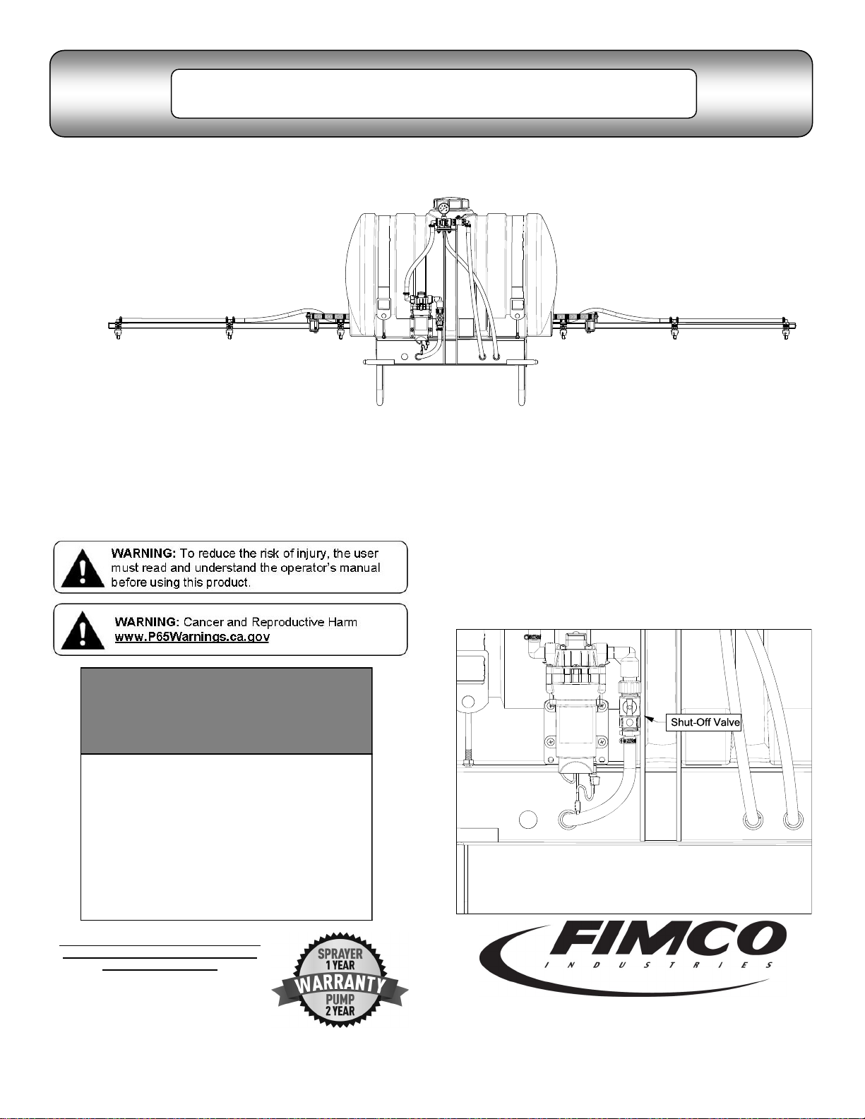
When spraying with either the boom or the handgun, pressure may
be reduced by slowly opening the bypass valve until desired
pressure is achieved. Opening the valve decreases pressure, closing
the valve increases pressure. When spraying with the boom, the
proper method to set the pressure is to open the boom valve
completely and if a lower pressure is desired, then slowly open the
bypass valve until that pressure is obtained.
For the safest and most efficient chemical application, you will need
to calibrate your sprayer using the tip and speed charts. Once you
have determined the proper speed and pressure settings, you will
need to consult your chemical label for the amount of chemical to be
added to the tank. Read the entire label. Use only according to label
directions.
The nozzles on the boom will spray an 100 inch wide swath. Check
the nozzle pattern by spraying water on a concrete surface.
Calibration
Chemical labels may show application rates in gallons per acre,
gallons per 1000 square feet or gallons per 100 square feet. You will
note that the tip chart shows 2 of these rating systems.
Speed Chart
Time Required in seconds to travel a distance of
Speed in M.P.H.
(Miles Per Hour) 100 Ft. 200 Ft. 300 Ft.
1.0 68 sec. 136 sec. 205 sec.
2.0 34 68 102
3.0 23 45 68
4.0 17 34 51
5.0 14 27 41
6.0 11 23 34
7.0 9.7 19 29
8.0 8.5 17 26
9.0 7.6 15 23
10.0 6.8 14 20
Once you know how much you are going to spray, then determine
(from the tip chart) the spraying pressure (PSI), and the spraying
speed (MPH).
Determining the proper speed of the pulling vehicle can be done by
marking off 100, 200 & 300 feet. The speed chart indicates the
number of seconds it takes to travel the distances. Set the throttle
and with a running start, travel the distances. Adjust the throttle until
you travel the distances in the number of seconds indicated by the
speed chart. Once you have reached the throttle setting needed,
mark the throttle location so you can stop and go again, returning to
the same speed.
Add water and proper amount of chemical to the tank and drive to
the starting place for spraying.
Using the Boom Nozzles
Four things must be considered before spraying with the boom.
How much chemical must be mixed in the tank.
Rate of spray (gallons per acre to be sprayed).
What pressure (p.s.i.) will be used.
Speed traveled (mph) while spraying.
Refer to the chemical label to determine your chemical mixture
See the tip chart to determine the pressure to be used. The
chart will also show the speed used when spraying.
Start the pump and open the valve to the boom nozzles.
Check the spray pattern. Usually you can see the coverage
better on a solid concrete surface, such as a driveway.
Raise or lower the nozzles so that you will have a good
coverage pattern. Generally the proper height
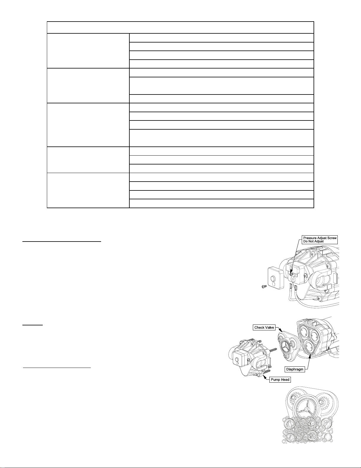
Maintenance During/After Spraying
Periodically check the strainer and clean the screen on your intake
line.
Proper care and maintenance will prolong the life of your sprayer.
Spray Tip Rate Chart (20" Spacing)
Tip
No.
Pressure
(psi)
Capacity
(GPM)
Gallons Per Acre - Based on Water
1
MPH
2
MPH
3
MPH
4
MPH
5
MPH
6
MPH
8
MPH
AIXR11002VP
15 .12 35.6 17.8 11.8 8.9 7.1 5.9 4.5
20 .14 41.6 20.8 13.8 10.4 8.3 6.9 5.2
30 .17 50.4 25.2 16.8 12.6 10.1 8.4 6.3
40 .20 59.6 29.8 19.8 14.9 11.9 9.9 7.4
Tip
No.
Pressure
(psi)
Capacity
(GPM)
Gallons Per 1000 Sq. Ft. - Based on Water
1
MPH
2
MPH
3
MPH
4
MPH
5
MPH
6
MPH
8
MPH
AIXR11002VP
15 .12 .41 .27 .20 .16
20 .14 .48 .32 .24 .19
30 .17 .58 .39 .29 .23
40 .20 .68 .45 .34 .27

Page 3
After use, drain the tank and store or dispose of chemical properly.
Fill the sprayer half way with clean water. Start the pump and allow
the water to pump through the entire plumbing system and nozzles.
Drain and then refill half full, add the recommended amount of a
good quality tank cleaner, such as FIMCO Tank Neutralizer and
Cleaner. (If no tank cleaner is available, you may substitute dish
soap for this step, about 1-2 oz. per gallon). Turn pump on and
circulate through system for 15 minutes and then spray out through
boom and handgun nozzles. Refill sprayer half way with clean water
and repeat. Follow the chemical manufacturer’s disposal instructions
of all wash or rinsing water.
If boom or handgun nozzles need cleaning, remove them from the
sprayer and soak in warm soapy water. Clean with a soft bristled
brush or toothpick if necessary. Never use a metal object. Even the
slightest damage can change the flow rate and spray distribution.
Water rinse and dry the tips before storing.
WARNING: Some chemicals will damage the pump valves if
allowed to soak untreated for a length of time! ALWAYS flush
the pump as instructed after each use. DO NOT allow chemicals
to sit in the pump for extended times of idleness. Follow the
chemical manufacturer’s instructions on disposal of all waste
water from the sprayer.
Winter Storage
Prepare the sprayer for end-of-season storage by running RV
antifreeze through the system. This will keep internal parts lubricated,
protect against corrosion and keep the unit from freezing. Note: RV
antifreeze is non-toxic and biodegradable and generally safer for the
environment than automotive antifreeze.
Before storing your sprayer for winter or long term storage,
thoroughly clean and drain it as much as possible. Then pour enough
pink RV antifreeze into the tank so that when the pump is turned on
you can pump the antifreeze throughout the entire plumbing system,
including the bypass. Make sure to operate the boom and handgun
until you see pink fluid spraying from the nozzles. Leave any
remaining antifreeze in the tank. Before your next usage, rinse the
antifreeze from the sprayer with clean water.
It is nearly impossible to drain all of the water from the sprayer and
any trapped water can freeze in cold weather and damage parts of
the sprayer. Pumping the antifreeze through the system will displace
the water and help prevent this damage.
Removing from storage: drain the antifreeze. Fill the tank with fresh
water and run through the system. Dispose of antifreeze and flush
water properly.
Strap/Buckle Detail
Strap Attachment to a “Flat” Buckle
The nylon straps are to be inserted in and out of the
slots in the buckle, as shown. Be sure the straps are
snug before tightening the hook bolts. In most cases, it
will be necessary to re-tighten the straps after filling the
tank with liquid.
Corrosion Resistant Materials: Wetted Parts Polypropylene, 316SS and Polyethylene
Maximum Pressure = 150 p.s.i.
Large Capacity - 12.5 G.P.M. @ 5 p.s.i. Pressure Drop
3/4” NPT (F) Inlet Connection
1/2” NPT (F) Spray Line Connection
3/4” NPT (F) Continuous By-Pass Connection
Valves may be connected w/close nipples for
multiple section spray control
‘Directo Valve’ - Manually Operated Control Valve
Fimco # Mfg. Part #
5143316 AA6B
5168718 PK-AB6B-KIT
Description
Directo-Valve (AA6B)
Repair Kit, Items Marked * *
* * Available only in Repair Kit
♦ ♦ Only Available in Complete Assembly

Page 4
DO
Clean and rinse your pump after each use with Fimco Tank
Neutralizer
Winterize your pump or sprayer by rinsing, draining and
running RV Antifreeze through it before storing for the winter.
Use clean water for your spray mixture
Store inside a building when not in use.
DON’T
Use to pump bleach.
Use to pump petroleum products such as diesel fuel,
gasoline or kerosene
Leave your pump sit with spray mixture in it for extended
periods
Use dirty or unfiltered water for spraying
Troubleshooting the Pump:
Motor does not run:
Check for loose wiring connection(s).
Make sure the 'ON/OFF' switch in the lead wire assembly
is in the 'ON' position. "I" is the 'ON' position and 'O' is
the 'OFF' position.
Check for defective pressure switch. Make sure you are
connected to a good 12 volt power source. Make sure
any on/off switches are in the 'on' position. Remove the
cap to the pressure switch. Pull both red wires off of their
terminals, and touch the two ends together. If your pump
runs when you do this, your pressure switch will need to
be replaced.
Check the fuse.
Check for low voltage at the power supply.
Pump does not prime:
Check for air leaks in supply line.
Check for debris in the check valve assembly.
Check for defective check valve.
Check for clogged strainer/filter.
Check for cracks in the pump housing.
Check for empty product supply.
Low Pressure/Low Flow:
Check for leaks in the discharge line.
Check for restriction in the discharge line.
Check for debris in nozzle orifice.
Check for clogged strainer.
Check for proper voltage—try another 12-volt battery.
Pulsating flow (surging):
Low flow may cause pump to surge.
Spray wand is adjusted for a small or fine spray pattern.
Slightly open bypass (if applicable) to overcome.
If needed, pressure switch may need to be adjusted—
adjust a quarter turn at a time clockwise until surging
stops.
Check for defective pressure switch.
Check for leaks in the discharge line.
Check for restriction in the discharge line.
Check for debris in nozzle orifice.
Discharge hose may be too long.
Check for clogged strainer.
Motor continues to run after discharge is shut off:
Check for empty product supply.
Check for open bypass valve. (if equipped)
Check for low voltage.
Check for leak in discharge line.
Check for defective pressure switch.
System has leaks.
Fuse blows:
Excessive voltage.
Improper adjustment of pressure switch.
Damaged or defective wiring harness.
Half-moon & counterweight are sticking.
Defective pressure switch.
Pump Model: 5281371
Available Replacement Parts
Replacement Pump: 5151087
Includes:
1/2” MNPT Port Kit Fitting
#5168832
1/2” Hose Barb Port Kit Fitting
#5168833
3/8” Hose Barb Port Kit Fitting
#5168836

Page 5
Try another 12-Volt battery
Quarter turn at a time clockwise until surging stops
Defective pressure switch
Troubleshooting
Bypass is not completely closed
System has leaks
Check for worn or dirty check valve
Excessive voltage
Improper adjustment of pressure switch
Damaged or defective wiring harness
Check for proper voltage
Check for worn or dirty check valve
Low flow may cause pump to surge
Spray wand is adjusted for a small or fine spray pattern
Slightly open bypass (if applicable) to overcome
If needed, pressure switch may need to be adjusted
Pump will not run:
Low Pressure/Low Flow:
Pump surges:
Pump continues to run:
Fuse blows:
Check for loose wiring
Make sure the ON/OFF switch is on
Check the fuse
Check for defective pressure switch
Check for a clogged strainer
Cleaning the Check Valve:
If you’re experiencing little to no pressure or the pump is not priming and you’ve checked your
filter screen and it’s clean, and you’ve gone through the other trouble shooting tips, you may
need to clean the check valve.
Remove the head of the pump, which is held on by 7 screws.
The first piece inside the head of the pump is called a check valve, it’s the part responsible for building up pressure
and pumping water/solution through the lines.
Clean the check valve under hot, soapy water (such as a good grade dish soap).
Give it a very light scrubbing with something like an old toothbrush, something with soft bristles.
Then let it soak for about an hour or so in the hot soapy solution and replace in the pump and reassemble the pump.
Most times this will restore most, if not all of the prime of a pump.
If you’re still having issues with pressure after this step, it would be recommended to replace this part.
Checking the Pressure Switch:
If your motor is not running and you’ve checked the following: for loose wiring connections, fuse, the switch on the
lead wire was “ON” and made sure you were connected to a fully charged battery and everything is fine, but the
motor won’t run, then it’s time to check to see if the pressure switch is bad.
Remove the cover off the 1” square box (pressure switch) on the head of the pump, the cover is held on by
one phillips-head screw. This will expose the two red wires.
With the pump connected to a good 12 volt power source and everything on.
Slip the two red wires off the terminals and touch them together.
If the motor runs, it means the pressure switch is bad and needs to be replaced.
If it still doesn’t run, try bypassing the switch in the lead wire or using another lead wire. Even if a tester shows power
to the pressure switch, it still could be the switch in the wire that is causing the problem. If still not responsive, use a
voltmeter or electrical tester to make sure you are getting power to the head of the pump, as it could possibly be
something in one of the wires or even the lead wire assembly may need to be replaced.
Warning: It is NOT recommended to run the pump this way, as the pump will continue
to run and not shut off.
This could result in blown hoses when all discharges are closed.
Also, this could result in premature failure of the pump completely.

Page 6
See Detail B
1/2” Bulkhead Fitting
TF50DTN
Exploded View:
LG-55-3PT-12V
(5300845)
Refer to the parts list on
next page for part numbers.
Hose Connections for Valve Assembly
Detail B
See Detail A
Detail A

Page 7
CROSS TEE ELL
Exploded View:
See Hinge Detail
Opposite side has typical hardware setup
Clamp
Bag of 7: 5277730
Parts List: LG-55-3PT-12V (5300845)
Hinge Detail
Nozzle Detail
Refer to the parts list on above
for part numbers.

Page 8
LIMITED WARRANTY FOR NEW FIMCO, IND. EQUIPMENT
WHO MAY USE THIS LIMITED WARRANTY. This limited warranty (the “Limited Warranty”) is provided by Fimco, Ind. to the original purchaser
(“you”) of the Equipment (as dened below) from Fimco, Ind. or one of Fimco, Ind.’s authorized dealers. This Limited Warranty does not apply to
any subsequent owner or other transferee of the Equipment. THIS LIMITED WARRANTY GIVES YOU SPECIFIC LEGAL RIGHTS, AND YOU MAY ALSO
HAVE OTHER RIGHTS WHICH VARY FROM STATE TO STATE.
WHAT THIS LIMITED WARRANTY COVERS AND FOR HOW LONG. Fimco, Ind. warrants that any new Equipment will be free from defects in
material and workmanship for a period of one (1) year for sprayer and two (2) years for High-Flo High Performance pump (homeowner), 90 days
for sprayer and pump (commercial user), aer delivery of the Equipment to you (the “Warranty Period”). The Warranty Period is not extended if
Fimco, Ind. repairs or replaces the Equipment.
WHAT IS NOT COVERED BY THIS LIMITED WARRANTY. This Limited Warranty does not apply to: (1) used Equipment; (2) any Equipment that has
been altered, changed, repaired or treated since its delivery to you, other than by Fimco, Ind. or its authorized dealers; (3) damage or deprecia-
on due to normal wear and tear; (4) defects or damage due to failure to follow Fimco, Ind.’s operator’s manual, specicaons or other wrien
instrucons, or improper storage, operaon, maintenance, applicaon or installaon of parts; (5) defects or damage due to misuse, accident or
neglect, “acts of God” or other events beyond Fimco, Ind.’s reasonable control; (6) accessories, aachments, tools or parts that were not manu-
factured by Fimco, Ind., whether or not sold or operated with the Equipment; or (7) rubber parts, such as res, hoses and grommets.
HOW TO OBTAIN WARRANTY SERVICE. To obtain warranty service under this Limited Warranty, you must (1) provide wrien noce to Fimco,
Ind. of the defect during the Warranty Period and within thirty (30) days aer the defect becomes apparent or the repair becomes necessary, at
the following address: Fimco, Ind., 1000 Fimco Lane, North Sioux City, SD 57049; and (2) make the Equipment available to Fimco, Ind. or an
authorized dealer within a reasonable period of me. For more informaon about this Limited Warranty, please call: 800-831-0027.
WHAT REMEDIES ARE AVAILABLE UNDER THIS LIMITED WARRANTY. If the condions set forth above are fullled and the Equipment or any part
thereof is found to be defecve, Fimco, Ind. shall, at its own cost, and at its opon, either repair or replace the defecve Equipment or part.
Fimco, Ind. will pay for shipping and handling fees to return the repaired or replacement Equipment or part to you.
LIMITATION OF IMPLIED WARRANTIES AND OTHER REMEDIES. THE REMEDIES DESCRIBED ABOVE ARE YOUR SOLE AND EXCLUSIVE REMEDIES,
AND FIMCO, IND.’S SOLE LIABILITY, FOR ANY BREACH OF THIS LIMITED WARRANTY. TO THE EXTENT APPLICABLE, ANY IMPLIED WARRANTIES,
INCLUDING, WITHOUT LIMITATION, THE IMPLIED WARRANTIES OF MERCHANTABILITY AND FITNESS FOR A PARTICULAR PURPOSE, SHALL BE LIM-
ITED IN DURATION TO THE WARRANTY PERIOD, AND THE REMEDIES AVAILABLE FOR BREACH THEREOF SHALL BE LIMITED TO THE REMEDIES
AVAILABLE UNDER THIS EXPRESS LIMITED WARRANTY. SOME STATES DO NOT ALLOW LIMITATIONS ON HOW LONG AN IMPLIED WARRANTY
LASTS, SO THE ABOVE LIMITATION MAY NOT APPLY TO YOU. IN NO EVENT SHALL FIMCO, IND.’S LIABILITY UNDER THIS LIMITED WARRANTY EX-
CEED THE ACTUAL AMOUNT PAID BY YOU FOR THE DEFECTIVE EQUIPMENT, NOR SHALL FIMCO, IND. BE LIABLE, UNDER ANY CIRCUMSTANCES,
FOR ANY CONSEQUENTIAL, INCIDENTAL, SPECIAL OR PUNITIVE DAMAGES OR LOSSES, WHETHER DIRECT OR INDIRECT. SOME STATES DO NOT
ALLOW THE EXCLUSION OR LIMITATION OF INCIDENTAL OR CONSEQUENTIAL DAMAGES, SO THE ABOVE LIMITATION OR EXCLUSION MAY NOT
APPLY TO YOU.
Warranty
Based on the minimum overlap required to obtain uniform
distribuon with 110° ps and 20” spacing.
Suggested Minimum Spray Height: 16”-18” above what is
being sprayed (to plant, not ground).
Opmum Spray Height: 20”
110° wide, tapered flat spray angle with air induction tech-
nology for better drift management
Made of 2-piece UHMWPE polymer construction which
provides excellent chemical resistance, including acids, as
well as exceptional wear life
Compact size to prevent tip damage
Excellent for systemic products and drift management
This manual suits for next models
1
Table of contents
Other Fimco Paint Sprayer manuals

Fimco
Fimco LG-25-PM User manual

Fimco
Fimco ATV-25-700-QR User manual

Fimco
Fimco LG-14-PM User manual

Fimco
Fimco 65-5N-UTV-GS User manual

Fimco
Fimco 3PT-65-6R-BL User manual

Fimco
Fimco BK-1 User manual

Fimco
Fimco BB-304 User manual

Fimco
Fimco ATVBK-500 Parts list manual

Fimco
Fimco UTL-40-12V User manual

Fimco
Fimco SK-61-12V User manual

Fimco
Fimco 3PT-200-8R-1225FX4 User manual

Fimco
Fimco TR-40-EX User manual

Fimco
Fimco LG-13-P User manual

Fimco
Fimco LSS-280-E User manual

Fimco
Fimco ATVBK-700-QR User manual

Fimco
Fimco LG-20-TRL User manual

Fimco
Fimco LG-8-P User manual

Fimco
Fimco UTL-60-7 User manual

Fimco
Fimco 3PT-110-NR-1025FX4 User manual

Fimco
Fimco LG-20-P User manual