Fimco UTL-40-5 User manual

Form No. 869 [5004621 (02/12)] Printed in the U.S.A.
Assembly
Most of the sprayer has been assembled at the factory.
Join the center boom member to the boom mounts with the bolts
and nuts provided. Make sure the outer boom members fold
'backwards'. See exploded view later in this manual for reference.
Attach the boom feeder hose to the boom. Secure in place with a
hose clamp provided.
Model: UTL-40-5 (5301399)
(40 Gallon, 12 Volt, Utility Sprayer w/5-Nozzle Boom Assembly)
Owner's Manual
1000 FIMCO Lane, P.O. Box 1700, North Sioux City, SD 57049
Toll Free Phone: 800-831-0027 : Toll Free Fax: 800-494-0440
www.fimcoindustries.com
General Information
Thank you for purchasing this product. The purpose of this
manual is to assist you in operating and maintaining your utility
sprayer. Please read it carefully, as it furnishes information which
will help you achieve years of trouble-free operation.
Open the tank lid and be sure the tank is clean and free of foreign
material. Fill the tank about 1/2 full with plain water.
NOTE:
It is VERY important for you to test your sprayer with plain
water before actual spraying is attempted. This will enable
you to check the sprayer for leaks, without the possibility of
losing any expensive chemicals.
Before starting, open the suction line valve. (located near the
pump) Check for leaks.
Open the valve for the boom. Make sure your pattern is sufficient.
You may decrease pressure in the system by 'bypassing' solution
back into the tank. This is achieved by opening the valve
opposite of the boom valve. Regulating pressure is done in this
manner.
During the testing period, be sure to observe the spray pattern
given by the spray nozzles. If there is any pattern distortion, it will
be necessary to remove and clean the affected tips.
Caution: Never use a metal object or other sharp item for
cleaning a nozzle tip. It is better to use a nozzle brush (NOT
wire brush) or compressed air for tip cleaning.
Testing the Sprayer
- 5 Nozzle Boom Assembly, 100" Spray Coverage
- 12 Volt / 60 p.s.i. / 2.1 g.p.m. / 8 Amp Diaphragm Pump
- Deluxe Pistol-Grip Handgun w/25 Feet of 3/8" Hose
- Bypass (Recirculation) Line
Technical Specifications
Warranty/Parts/Service
Products are warranted for one year from date of purchase
against manufacturer or workmanship defects.
Commercial users have a 90 day warranty.
Your authorized dealer is the best source of replacement parts
and service. To obtain prompt, efficient service, always
remember to give the following information...
- Correct Part Description and/or part number.
- Model number/Serial number of your sprayer.
Part descriptions and part numbers can be obtained from the
illustrated parts list section(s) of this manual.
Whenever you need parts or repair service, contact your
distributor/dealer first. For warranty work, always take your
original sales slip, or other evidence of purchase date, to your
distributor/dealer.

Gallons Per 100 Sq. Ft. - Based on Water
Gallons Per 1000 Sq. Ft. - Based on Water
Gallons Per Acre - Based on Water
Capacity
Pressure
Spray
Tip
Height
2
No.
40
50
18"
30
20
(psi)
.076
.068
.059
.048
MPH
.136.20
.23 .152
.17
.14
(GPM)
.118
.096
MPH
1
.034.045
.051 .038
.039
.032
MPH
3 2
.030
.024
MPH
4
Capacity
Capacity
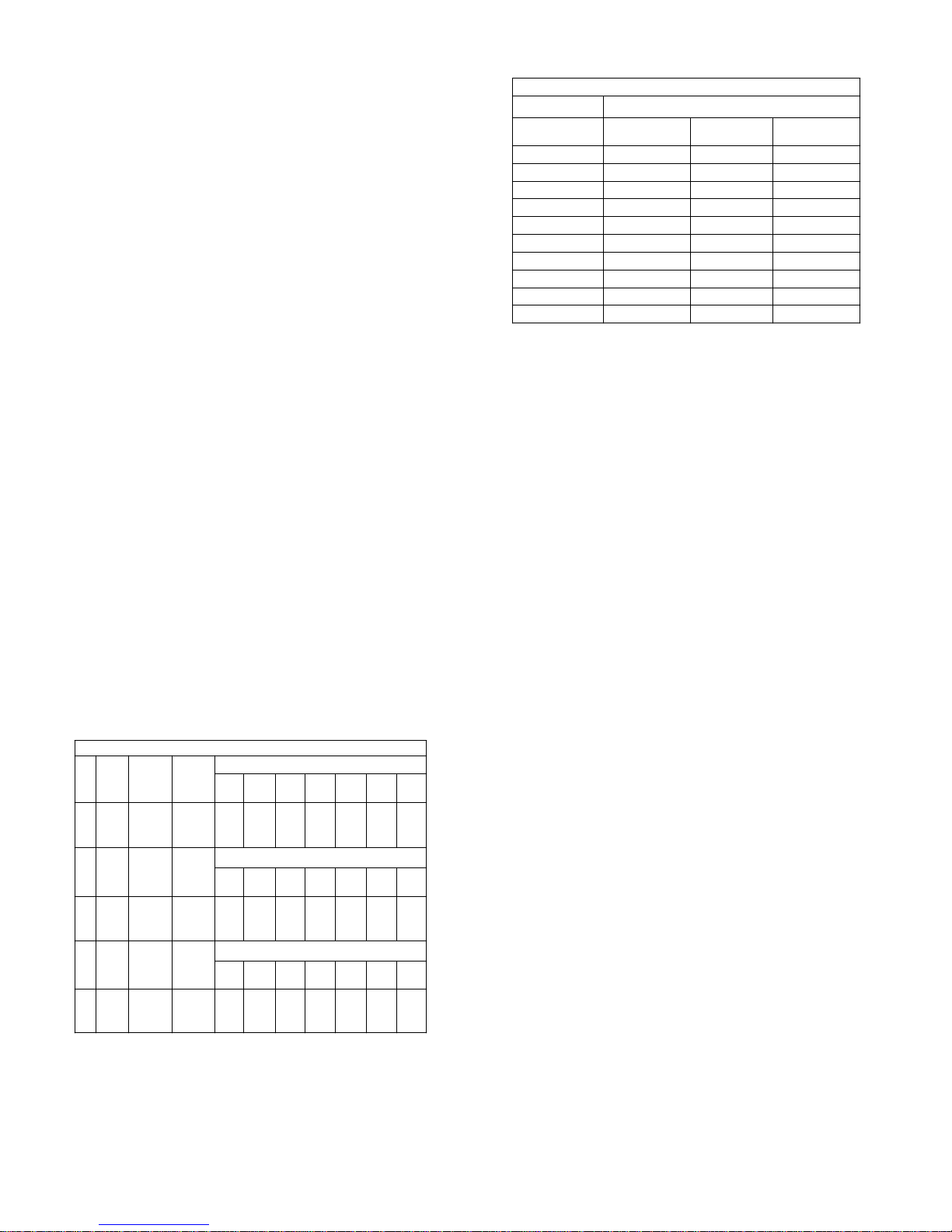
Rate Chart for 8002 Spray Tip
50
Height
Spray
2
Tip
No.
20
18"
50
30
40
Pressure
(psi)
Height
Spray
No.
2
Tip
(psi)
18"
20
40
30
Pressure
16.622.233.266.4.23
.76
.68
.59
.48
MPH
.96.14
.23
.20
.17
1.52
1.36
1.18
(GPM)
MPH
1
.24.32
.51
.45
.39
.38
.30
.34
MPH
3 2
MPH
4
29.6
25.6
20.9
MPH
1
(GPM)
.14
.20
.17
41.8
59.2
51.2
MPH
4
3 2
19.8
17.2
14.0
MPH
10.5
14.9
12.9
MPH
.015
.014
.012
.010
MPH
10
.018.027
.031 .020
.024
.019
MPH
5
.016
.013
MPH
7.5
6.68.813.3
.15
.14
.12
.10
MPH
10
.13.19
.31
.27
.24
.20
.16
.18
MPH
5
MPH
7.5
5.9
5.1
4.2
MPH
10
7.5 5
8.4
11.9
10.3
MPH
5.6
7.9
6.9
MPH
Time Required in seconds to travel a distance of:
17 344.0
5.0
6.0
7.0
9.0
8.0
10.0
7.6
6.8
9.7
8.5
14
11
15
14
19
17
23
27
100 Ft.
68 sec.
2.0
3.0
1.0
(Miles per Hour)
Speed in M.P.H.
Speed Chart
136 sec.
34
23 45
68
200 Ft.
51
23
20
26
29
41
34
205 sec.
300 Ft.
102
68
Page 2
The performance of any agricultural chemical depends upon
the proper application
The tips supplied as standard with the sprayer can be used for
a wide variety of spraying applications. Other tip sizes are
available for different coverages. The speed and pressure
charts shown indicate the rates can be changed considerably
by changing speed and pressure. The nozzles on the boom will
spray a 100" wide swath. The proper nozzle height is 17" to 20"
above the object being sprayed.
Check the spray patterns. Each nozzle should overlap the next
nozzle approximately 30%.
The pumping system draws solution from the tank,
through the strainer/filter, and to the pump. The pump forces
the solution under pressure to the handgun and/or boom
nozzles.
Open the handgun by squeezing the handle lever.
•
Rotating the adjustable nozzle tip on the handgun will
•
change the tip pattern from a straight stream to a cone
pattern (finer mist).
Conditions of weather and terrain must be considered when
setting the sprayer. Do not spray on windy days. Protective
clothing must be worn in some cases.
Be sure to read the chemical label(s) correctly!
WARNING:
Some chemicals will damage the pump valves if
allowed to soak untreated for a length of time. ALWAYS
thoroughly flush the pump with water after use. DO NOT allow
chemicals to sit in the pump for extended times of idleness.
Follow the chemical manufacturer's instructions on disposal of
all waste water from the sprayer.
When you are ready to spray, mix chemicals as follows. Add
the proper amount of water to the tank. Run the sprayer while
adding chemical to the water. Do NOT spray through the boom
at this time. This will allow the solution to return (or 'bypass') to
the tank. The movement of solution through the bypass will aid
in mixing the water and chemicals. You should now be ready to
spray.
Operation & Calibration
- Four things must be considered before spraying with the boom:
How much chemical must be mixed in the tank?
1.
Rate of spray? (Gallons per Acre to be sprayed)
2.
What Pressure (p.s.i.) will be used?
3.
Speed Traveled (m.p.h.) while spraying?
4.
- Refer to your chemical's label to determine the chemical mixture.
- See the tip chart to determine the pressure to be used. The chart
will also show the speed used when spraying.
- If the towing vehicle does not have a speedometer, speed can
be determined as per the directions.
Determining the proper speed of the pulling vehicle can be done
by marking off 100, 200, & 300 feet. The speed chart indicates the
number of seconds it takes to travel the distances. Set the throttle
and with a running start, travel the distances. Adjust the throttle
until you travel the distances in the number of seconds indicated
by the speed chart. Once you have reached the throttle setting
needed, mark the throttle location so you can stop and go again,
returning to the same speed.
Add water and proper amount of chemical to the tank and drive to
the starting place for spraying.
Once you know how much you are going to spray, then determine
(from the tip chart) the spraying pressure (PSI), and the spraying
speed (MPH). The pressure can be set by running the sprayer
with the boom nozzles 'on', and then adjusting the relief valve until
the gauge reads the desired pressure. Notice that the pressure
will go up when the boom line is shut off. This is normal, and the
pressure will return as before when you open the boom line.
When selecting pressure from the tip chart, it is a good idea to try
for the 20 or 30 p.s.i. range as this allows an excellent nozzle
pattern. Spraying at 10 p.s.i. begins to break up the pattern, and
at 40 p.s.i. you may notice some drift.

After Spraying
After use, fill the sprayer tank part way with water. Start the
sprayer, and allow the clear water to be pumped through the
plumbing system and out through the spray nozzles.
Refill the tank about half full with plain water and use FIMCO
Tank Neutralizer and Cleaner, and repeat cleaning instructions
above.
Flush the entire sprayer with the neutralizing/cleaning agent,
then flush out one more time with plain water. Follow the
chemical manufacturer's disposal instructions of all wash or
rinsing water.
For the boom, (if applicable) remove the tips and screens from
the nozzle assemblies. Wash these items out thoroughly. Blow
the orifice clean and dry. If the orifice remains clogged, clean it
with a fine bristle (NOT WIRE) brush, or with a toothpick. Do
not damage the orifice. Water rinse and dry the tips before
storing.
WARNING: Some chemicals will damage the pump valves
if allowed to soak untreated for a length of time! ALWAYS
flush the pump as instructed after each use.
3.3
If none of the above will work, try pulling wire terminal "A" off of the spade terminal of the pressure switch, and cross it over and touch terminal "B". (You will need to
remove the pressure switch cap before doing this) If your pump runs when you do this, you know you will need to replace your pressure switch.
Another thing you can try is to take apart the switch box on the lead wire assembly (#5274443) with the (2) phillips head screws, and 'hot-wire' it together. Take the
(2) wires that are screwed to the rocker switch, off of the switch and twist them together. This will insure you are getting the full 12 volts to the pump. If your pump
- Check line strainer (screen) at the inlet location, at the tank. You will need to unscrew the knurled nut to access this screen. (see exploded view later in this manual)
The ON/OFF valve should be closed while performing this, to insure you do not lose any solution. Periodically take the screen at this location out and clean it.
- Unscrew the head portion of your pump and remove the check valve assembly from inside. You need to make sure the O-Ring comes out with this piece as well.
(See the exploded view to help identify these components) These pieces can be cleaned which, in most cases, will help restore some, if not most, of your prime.
Soak this check valve in a solution of hot water & a good quality brand of dishsoap. A little bit of 'scrubbing' with perhaps an old toothbrush may be required to
actually break up any build-up that may be on the check valve. Rinse off the pieces and replace them back into your pump. Reassemble the pump. Hook it back up
"B"
Troubleshooting the 2.1 g.p.m. Pump:
- Check inline fuse on the wires on the pump. If blown, replace with new fuse.
- Make sure BOTH on/off switches are in the 'on' (-) position.
- Make sure you 12 volt source (battery) is fully charged.
- Insure a tight connection at the battery clips.
runs after doing this, you will know that your lead wire assembly needs to be replaced.
- Make sure the bypass line valve is closed, to allow the pressure to build up in your system.
7.5 Amp Mini Fuse
Check Valve Kit (w/O-Ring)
Upper Housing Assembly
Pressure Switch Assembly
Pkg. (2) Clips (Port Fitting)
Diaphragm/Cam/Bearing Kit
Rocker Switch
Mounting Feet (Pkg of 4)
Pump runs, but does not prime:
and test.
Pump will NOT run:
Part
Number
5157205
5168820
5168837
5168839
5157202
20408-000
5168838
5095202
5157207
3.1
4
5.1
5.2
3.2
3.3
Item
1
2
3
No
1
Plunger Kit
1
1
1
1
1
Description
1
1
1
Qty
List
Price
3.99
19.95
39.95
7.99
23.95
3.41
18.99
4.99
6.99
3.2
4
3
3.1
(12 Volt, 8 Amp, 2.1 gpm, 60 psi)
#5275703 Pump
*
2
"A"
Fittings with an asterisk (*) by
them, come together in a bag,
(1) 5168833 - 1/2" Hose Barb
(1) 5168836 - 3/8" Hose Barb
part #7771824
(1) 5168832 - 1/2" MNPT
*
*
5.2
1
5.1
Page 3
**********************************************************************
Periodically close the suction line valve. Check the line strainer
and clean the screen.
Proper care and maintenance will prolong the life of your
sprayer.
Winter Storage
Drain all water out of your sprayer, paying special attention to
the pump, handgun, and valve(s). These items are especially
prone to damage from chemicals and freezing weather.
The sprayer should be winterized before storage by pumping a
solution of RV antifreeze through the entire plumbing system.
This antifreeze solution should remain in the plumbing system
during the winter months. When spring time comes and you
are preparing your sprayer for the spray season, rinse the
entire plumbing system out, clearing the lines of the antifreeze
solution. Proper care and maintenance will prolong the life of
your sprayer.

16
21
24
14
12
5
22
30.4 30.1
30.3
30.5
30.2
30.4 19
3
11
3
26
19
18
13
13
23
1
3
3
17
18
19
3
26
11
2
14 12
2
11
11
27
28
25
11
2
34
34
25
11
2
9
8
6
7 15 15
10 10
15 15
15 15
15 15
33
35
8 15 15 5
29.2
29.4
29.3.2
29.3.1
29.3.5
29.3.4
29.3.3
29.3.6
29.1
20
31.3
31.1
31.2
4
32.1
32.2
32.3
32.4
32.6
32.5
32.6
32.5
32.4
Page 4
Exploded View:
UTL-40-5 (5301399)

26.73
26.35
39.25
32.88
87.91
36.00 (Frame)
61.06
ELL
5-Nozzle Boom Assembly
Typ. 3xs
TEE
Typ. 2xs
ELL
TEE
21
H.H.C.S. 3/8"-16nc x 3 3/4" long
Flatwasher - 3/8"
3/8"-16 Hex Nut
Extension Spring
Square Cap, Black (1 1/4" Square Tube)
Outer Boom Weldment (5 Nozzle)
Center Boom Weldment (BK-70)
3/8"-16 Flange Locknut (Grade F)
3/8"-16 Hex Locknut
Boom Sub-Assembly (5-Nozzle)
Quick TeeJet Cap ONLY (Yellow)
80 Degree Flat Spray Tip, Yellow
Seat Washer (QJ Caps)
Nozzle Strainer, Red (50 Mesh)
Single Hose Shank (1/2" Hose)
QJ ELL Nozzle Assembly
Nylon Hose Tee, 1/2" HB
Quick TeeJet Cap ONLY (Yellow)
80 Degree Flat Spray Tip, Yellow
Seat Washer (QJ Caps)
Nozzle Strainer, Red (50 Mesh)
Double Hose Shank (1/2" Hose)
QJ TEE Nozzle Assembly
Hose Clamp (3/8"-1/2")
Hose, 1/2"-1 Brd. x 19 3/8"
Hose, 1/2"-1 Brd. x 23"
Hose, 1/2"-1 Brd. x 10"
QJ Harness Assembly (BA5SQK)
Vari-Quick Clamp (1 1/4" Sq. Tube)
Description
2527702614
1508600313
5034563
5016030
5006054
5019228
5046344
5277475
5274458
5006345
5006092
5277482
5046219
5018265
5016157
5116019
5056065
22
29
28
27
26
25
24
23
21
20
19
18
17
16
15
2
2
2
8
4
2
2
1
1
4
1
1
1
1
1
5046219
5018265
5016157
5116019
5056067
5277028
5051114
5020416
5020307
5020144
5277127
5272165
Number
5
12
11
10
9
8
7
6
4
3
2
1
No
Item
1
1
1
1
1
1
3
10
Part
5
2
2
1
Qty
25
14
4
24
1.06
.84
.25
.25
5.50
.36
40.55
.25
.25
.77
.89
.47
1.21
3.84
7
1
22
5
29
.77
.89
.47
1.21
3.84
.63
2.71
3.49
1.77
2.71
Price
List
7
1
27
28
23
26
815
12
9
10
11
19
16
17
18
13
1
3
26
1
4
22
27
28
21
29
1
24
25
Page 5
Parts List: UTL-40-5 (5301399)
(List Prices are Subject to Change)
Item
No
Part
Number
Qty
Description
List
Price
1 5006186 4
#10-24 Hex Whiz (Flange) Locknut
.25
2 5006259 16
3/8"-16 Hex Whiz (Flange) Locknut
.25
3 5006307 10
5/16"-18 Hex Whiz (Flange) Locknut
.25
4 5006351 1
1/2" Poly Nut
.59
5 5010039 2
Nylon Elbow, 1/2" MNPT x 1/2" HB
1.06
6 5020122 1
Hose, 1/2"-1 Brd. x 48"
5.88
7 5020135 1
Hose, 3/8"-1 Brd. x 25 Ft.
17.25
8 5020307 2
Hose, 1/2"-1 Brd. x 23"
3.49
9 5020462 1
Hose, 1/2"-1 Brd. x 31"
2.77
10 5034079 4
H.H.C.S. 3/8"-16nc x 1" Long
.25
11 5034099 10
H.H.C.S., 3/8"-16 x 3/4"
.50
12 5034101 3
H.H.C.S., 3/8"-16 x 1 3/4"
.50
13 5034159 2
Square U-Bolt, 5/16" x 1 5/16" x 1 7/8"
.99
14 5038698 4
Plastic Tank Hold-Down Leg Clip
2.93
15 5051114 10
Hose Clamp (3/8"-1/2")
.63
16 5058188 1
Tank Lid w/Lanyard
10.50
17 5075014 2
Rubber Grommet (Black)
2.79
18 5095176 2
Boom Mount, 40/60 Gallon Utility Sprayer
4.09
19 5117300 6
5/16"-18 x 1" Flange Whiz Lock Screw
.25
20 5167007 1
Pressure Gauge, 0-100 p.s.i.
6.75
21 5169245 1
40 Gallon Elliptical Tank (White)
105.00
22 5273959 1
Deluxe Pistol-Grip Handgun w/X-26 Tip
30.00
23 5274443 1
Lead Wire Assembly (w/Switch), 96"
9.99
24 5274880 1
Pkg. (2) Handgun Clips & (2) Screws
2.85
25 5274994 2
Slide Tube Weldment
8.99
26 5274997 2
Boom Mount Bracket Weldment
12.50
27 5275000 1
Upright Tube Weldment (L.H.)
12.01
28 5275001 1
Upright Tube Weldment (R.H.)
12.01
29 5275146 1
Pump Sub-Assembly
135.00
29.1 5275703 1
Gold Series 2.1 g.p.m. Pump
112.00
29.2 5010426 1
90 Deg. Port Elbow x 1/2" HB
2.25
Item
No
Part
Number
Qty
Description
List
Price
29.3 5275570 1
Filter/Valve Sub-Assembly
11.38
29.3.1 5005241 1
Nylon Swivel Adapter Spud, 1/2" NPT
1.25
29.3.2 5116242 1
Strainer, 1" Filter Washer
.31
29.3.3 5143188 1
Nylon Shut-Off Valve (3/4" GHT)
3.29
29.3.4 5010430 1
Port Kit Elbow, 1/2" FNPT
2.79
29.3.5 5006209 1
Poly Knurled Swivel Nut, 3/4" FGHT
.70
29.3.6 5067121 1
Poly Hose Fitting, 3/4" MGHT 1/2" HB
.55
29.4 5117176 4
#10-24 x 3/4" Phillips Truss Head Machine
Screw
.25
30 5275405 1
Valve Mount Sub-Assembly
36.33
30.1 5038704 1
Valve Mount Bracket
21.63
30.2 5038638 1
Handgun Holder Bracket
11.83
30.3 5006186 2
#10-24 Hex Whiz (Flange) Locknut
.25
30.4 5075014 2
Rubber Grommet (Black)
2.79
30.5 5117234 2
#10-24 x 1/2" Phillips Truss Head Machine
Screw
.25
31 5275501 1
Top Valve Sub-Assembly
12.44
31.1 5010193 1
Nylon Tee, 1/2" FNPT w/1/4" Port (Gauge)
9.44
31.2 5010039 1
Nylon Elbow, 1/2" MNPT x 1/2" HB
1.06
31.3 5010038 1
Nylon Elbow, 1/2" MNPT x 3/8" HB
1.05
32 5275502 1
Bottom Valve Sub-Assembly
11.28
32.1 5010148 1
Nylon Street Elbow, 1/2" MNPT x 1/2" FNPT
3.12
32.2 5005021 1
Nylon Adapter, 1/2" MNPT x 3/4" MGHT
.79
32.3 5143204 1
Dual Hose Shut-Off "Y" Valve
4.38
32.4 5016066 2
Garden Hose Washer
.20
32.5 5149011 2
Nylon Swivel, 1/2" Flat Seat Hose Barb
.58
32.6 5006055 2
Nylon Swivel Nut, 3/4" FGHT
.64
33 5275756 1
40-60 Gallon Utility Frame Weldment (Red)
95.00
34 5277486 2
Clamp Arm
35
BK-50
1
5-Nozzle Boom Assembly
147.50
Table of contents
Other Fimco Paint Sprayer manuals

Fimco
Fimco LG-65-BL-UTV User manual

Fimco
Fimco UTV-45-5-GS User manual

Fimco
Fimco BB-303 User manual

Fimco
Fimco LG-10-EC User manual

Fimco
Fimco LG-55-3PT-12V User manual

Fimco
Fimco 3PT-110-6R-1025FX4 User manual

Fimco
Fimco 5302316 User manual

Fimco
Fimco 3PT-45-12V-BL User manual

Fimco
Fimco 5301302 Parts list manual

Fimco
Fimco 200-3PT-17N-XL User manual

Fimco
Fimco WEED RANGLER WR-15-EC-B User manual

Fimco
Fimco LG-40-SS User manual

Fimco
Fimco LG-40-P User manual

Fimco
Fimco 150-3PT-5880 User manual

Fimco
Fimco BB-302 User manual

Fimco
Fimco 300G-3PT w/814 User manual

Fimco
Fimco TSSK-300 User manual

Fimco
Fimco 5301399 User manual

Fimco
Fimco LG-15-EC-SP User manual

Fimco
Fimco ATV-25-71-QR User manual