3
3. Assembly instructions
WARNING –BAccess to the zones inside the inverter must be carried out with the equipment disconnected from the network and from the
photovoltaic generator. Isolate the inverter by externally disconnecting the AC voltage and DC voltage as well as any voltage connected to
multifunction relays. Opening only the DC switches inside the inverter does not permit to operate in safe way considering that some internal parts
may remain at hazardous voltages.
ATTENTION –AWhen the PVS-50.0/60.0-GROUNDING KIT is assembled in one or more inverters connected in parallel to the same transformer
winding:
1.the inverters and the PV Array must be installed in Closed Electrical Operating Areas where the access is restricted to instructed persons.
The above is required because the below listed protections against electrical shock hazard on the PV arrays are not included inside inverter or do
not operate when grounding-kit is installed:
• Array insulation resistance detection for functionally grounded arrays
• Protection by application of Residual Current Devices
• Residual current monitoring for sudden changes
The following forms of shock hazard protections are provided integral to the inverter:
• Continuous residual current to ground
2. the maximum current flowing to earth, in case of ground fault on the DC side of the plant will be less than Nx500mA (PVS-50-TL) or Nx600mA
(PVS-60-TL) where N is the number of inverters connected to the same transformer winding. This current value must be considered to size the
wires and to evaluate the risk of fire.
ATTENTION –AThe earth protection circuit (PE) of the PV plant must have the same potential of the earth protection circuit (PE) of the building (in
case of roof-top installation).
WARNING –BThe extraneous conductive parts of the building and the earthed conductive parts of the plant must not be accessible simultaneously.
ATTENTION –AIt is not recommended to use the grounding kit in buildings with high risk of fire.
WARNING –BIt is not recommended to use the grounding kit in buildings with LPS (lightening protection systems) to avoid potential differences
among different earthed conductive parts of the PV plant that people can touch. Restricted access to PV plant reduces this hazard.
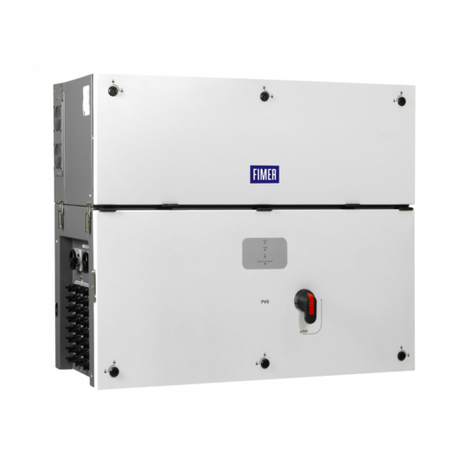
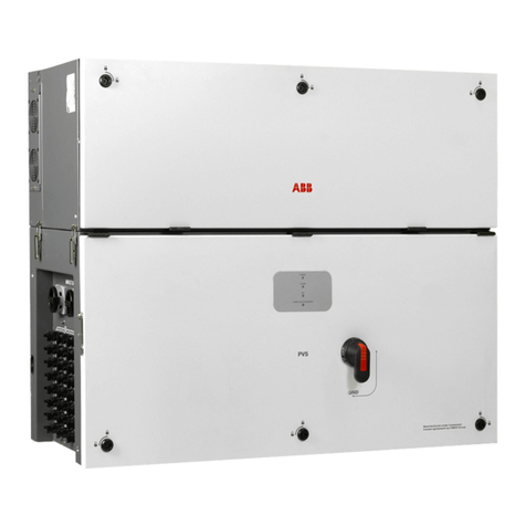
The GROUNDING KIT must be installed inside the wiring compartment.
• Open the front cover.
• Install the grounding board on the holder positioned on the lower side of the communication and control card (area highlighted in the figure to the side).
