FingerprintDoorLocks U10 User manual

1
Content
1Product Introduction ................................................................................ 5
1.1 Product Drawings .......................................................................... 5
1.1.1 Outside Drawing ........................................................................... 5
1.1.2 Dimensioned Drawing .................................................................. 6
1.2 Product Features ........................................................................... 6
1.3 Scope of Application ...................................................................... 6
1.4 Unlock Ways.................................................................................. 7
1.5 Technical Parameter...................................................................... 8
2Operation ................................................................................................ 9
2.1 Basic Functions ............................................................................. 9
2.1.1 Unlock Ways................................................................................. 9
2.1.2 Alarm Function.............................................................................. 9
(1)Low battery warning ..................................................................... 9
(2)Tamper alarm................................................................................ 9
2.1.3 Pseudo Password Alarm .............................................................. 9
2.2 Optional Functions....................................................................... 10
2.2.1 Normally-open Function ............................................................. 10
2.2.2 Latch Bolt Alarm Function........................................................... 10
2.2.3 Connecting the Handset Function .............................................. 10
2.2.4 Access Control Function............................................................. 10
2.2.5 Dip Switch Function.................................................................... 10
2.2.6 Double Lock Function................................................................. 11
2.2.7 Door Contact Function................................................................ 11
2.3 Operation and Administration ...................................................... 12
2.3.1 Keypad Operation Method.......................................................... 12
(1)Keypad Drawing ......................................................................... 12
(2)Password .................................................................................... 12
(3)Fingerprint Number..................................................................... 12
2.3.2 Management of Passwords and Fingerprints............................. 13
2.3.3 Unlock Ways............................................................................... 15
2.3.4 Right of Passwords and Fingerprints.......................................... 15
2.3.5 Points of Fingerprint Acquisition ................................................. 15

2
2.3.6 Emergency Power Supply .......................................................... 16
2.3.7 Installation of Batteries ............................................................... 16
3Installation and Adjustment ................................................................... 17
3.1 Installation Sketch ....................................................................... 17
3.2 Installation ................................................................................... 18
3.2.1 Step 1 Drilling Holes on the Door ............................................... 18
3.2.2 Step 2 Drilling Holes for Striking Box.......................................... 18
3.2.3 Step 3 Installation ....................................................................... 19
3.3 Notes for Installation.................................................................... 20
3.4 Adjustment................................................................................... 20
4Maintenance.......................................................................................... 21
4.1 Routine Maintenance................................................................... 21
4.2 FAQ ............................................................................................. 22
5Appendix ............................................................................................... 24
5.1 Packing list .................................................................................. 24
5.2 Tools for Installation..................................................................... 24

3
Important Notes
1 The fingerprint lock is a high-tech product and its installation will impact its operation and
lifetime directly. It is recommended to invite a professional to install the lock according to
the user manual. If the lock can not work after installation, please contact with local
distributor or agency freely for help.
2 If your apartment is under decoration, we recommend that you dismount the product and
re-install it after decoration. The aims are to avoid corrosion of the assembly caused by
corrosive substances in the decoration, which will accelerate the chemical changes on
product’s surface, and avoid the inflexibility of the lock caused by wet paint.
3 After installation and adjustment, please clear all fingerprints and password in factory
default and enroll your own administration password and fingerprints for security.
4 Beeps for low battery warnings will be heard if it is in low power. Please replace the
batteries timely and correctly.
5 If you are to be away for several days, or the lock does not need to work for a long time,
please take along with your mechanic key and remove the batteries.
6 For user who has difficulty to enroll his fingerprint due to poor fingerprint quality, he is
recommended to enroll with his thumb, and enroll over two fingerprints to improve the
rate of successful fingerprint acquisition.
7 The fingerprint template capacity is 100, while password capacity is 5 groups. Please
save new users' detailed information in Registration Form below for convenience of
management.
8 Factory default: password is 0+12341234 but no fingerprint is included.
9 Signals and LED light: For every successful operation, long beep will be heard once and
the green LED light will flash once; but when it fails, short beep will be heard for twice, the
red LED will flash once and then exit.
10 This user manual is applicable for U series products. U30 has been taken as the example
in figures and installation instruction in this manual.

4
Enrollment Form
To facilitate the administration of fingerprints and passwords, we have made a form for
administrators to record the details of enrollment. You can also design a form to meet your
requirements for enrollment.
Name
Fingerprint
No.
Password
No.
Registration
Date
Signature Note
5
1
Product Introduction
1.1
Product Drawings
1.1.1 Outside Drawing
01
02
03
04
06
07
08
09
10
12
13
11
05
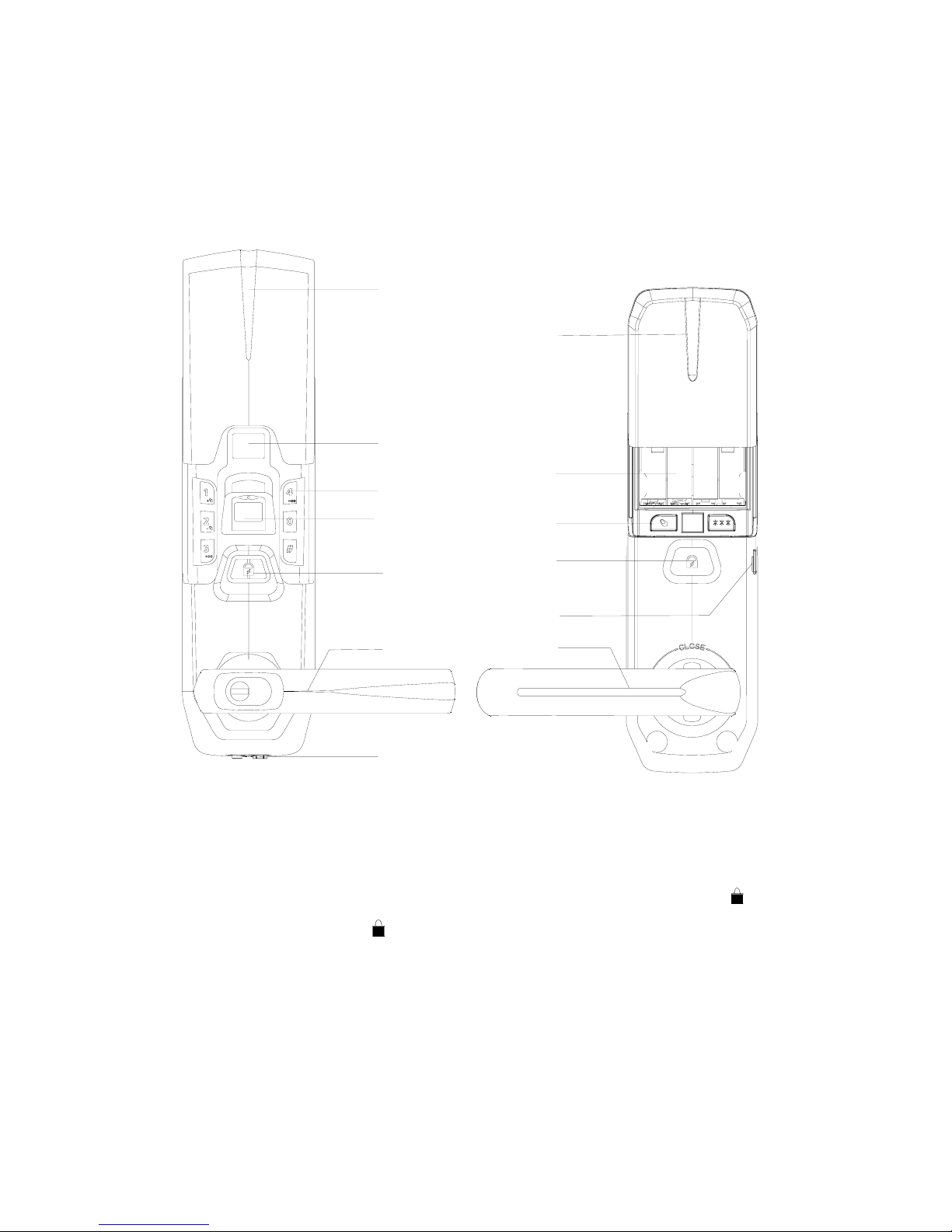
01 Exterior sliding cover
02 Nixie tube
03 Keypad
04 Reader
05 Exterior lock face button
06 Exterior lever
07 Emergency power supply interface
08 Battery pack cover
09 Batteries
10 clearance button
11 Interior lock face button
12 USB port
13 Interior lever
Note: No lever is included in U20.
6
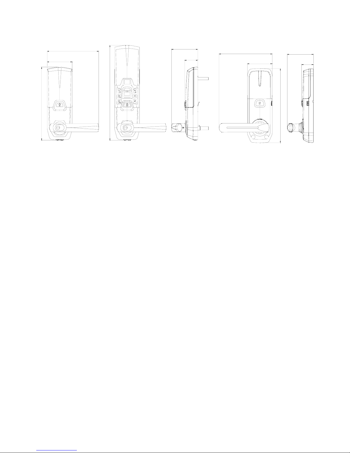
1.1.2 Dimensioned Drawing
76
155
221
287
39
79
75
160
224
36
79
Frontview Frontview Sideview Backview Sideview
1.2
Product Features
Support of unlocking the door by fingerprint, password and mechanical key;
Visual digital display and easy operation which are more convenient;
Zinc assembly which is more durable, delicate and attractive;
With functions of low battery warning, tamper alarm and pseudo password alarm;
Adoption of international advanced bio-technology is to ensure high quality of the product.
1.3
Scope of Application
Scope of application: government departments, public security bureau, army, banks, courts,
hospitals, office blocks, residential communities, etc.
7
1.4
Unlock Ways
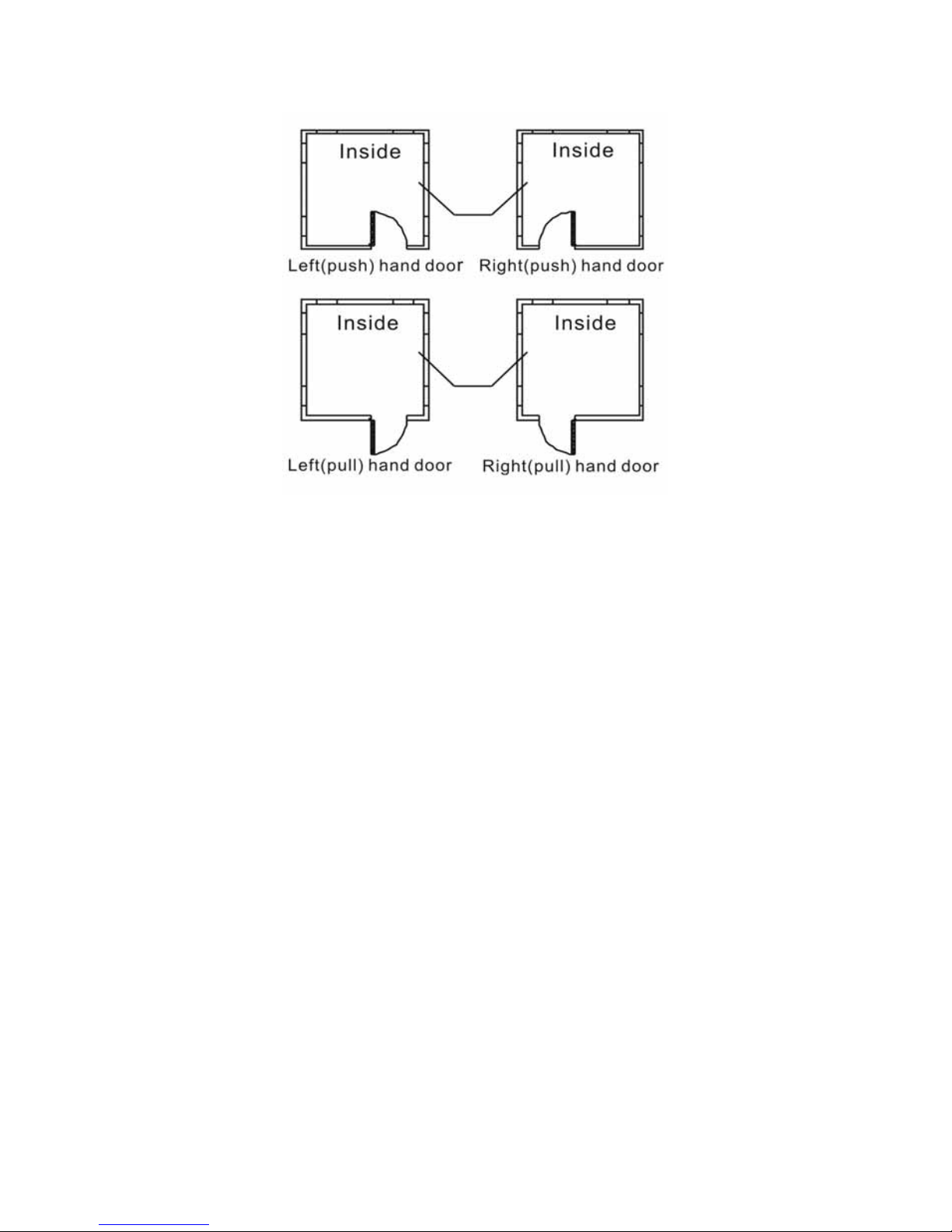
Left handed door: When you stand outside the door and the fixed hinges are on the left, the
fingerprint lock is then defined as left handed door, which is further divided into left (push)
handed door and left (pull) handed door.
Right hand door: When you stand outside the door and the fixed hinges are on the right, the
fingerprint lock is then defined as right handed door, which is further divided into right (push)
handed door and right (pull) handed door.
Note: For U20 product, you should set the dip switch of left/right handed door before the
installation. Check 2.2.5 for more details.

8
1.5
Technical Parameter
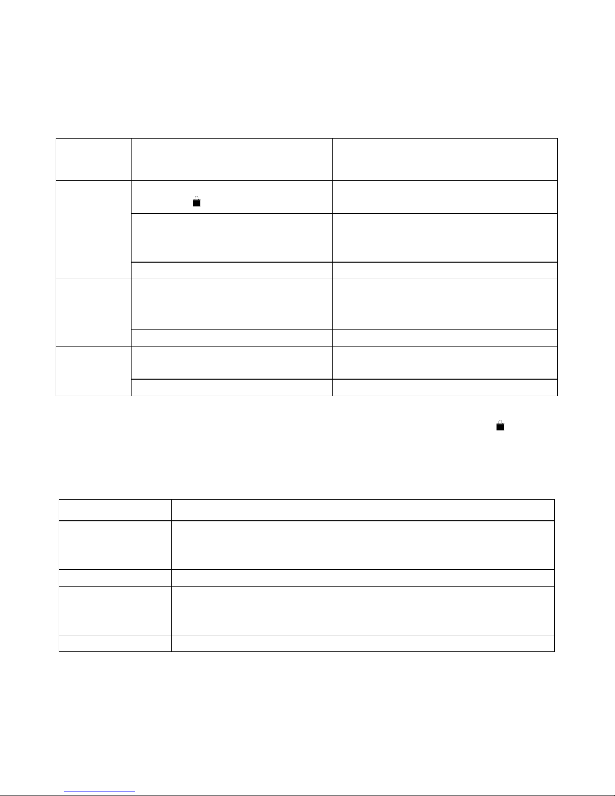
No. Item Technical Parameters
1 Sensor resolution Bright background, 500dpi
2 Anti-sabotage ability of sensor Free of damage by 1000 times of continuous
impact with a 4H pencil 20cm away.
3 Start-up time <1 second
4 Contrast 1:N
5 FRR ≤1%
6 FAR ≤0.0001%
7 Search angle 360°
8 Fingerprint enrollment module One fingerprint module is generated at a time
9 Fingerprint update method Automatic update
10 Fingerprint information The fingerprint information will not lose when
out of power or replacing batteries.
11 Fingerprint template capacity 100
12 Light interference Avoid bright and direct light
13 Reader Hard glass, nano-finish surface, extremely
resistant to friction
14 Static power consumption < 30 µA
15 Dynamic power consumption <250mA
16 Control system Single circuit
17 Password setting Random change and combine
18 Password length 9 digits (1-digit ID + 8 digits)
19 Lifetime of battery 5,000 times to unlock the door
20 Operating voltage 6V DC
21 Power supply mode Batteries
22 Password capacity 5 groups
23 Emergency power supply 9V DC
24 Low battery warning 4.9V
25 Anti-static 8KV for touch discharge, and 15KV for air
discharge
26 Operating temperature -20℃to 55℃
27 Operating humidity 10%-90%
28 Storage temperature -20℃to 70℃
29 Open door direction Left handed and right handed
30 Door access time period groups 10 groups
(Note: Parameters subject to change without prior notice for technology innovations by the
company).

9
2
Operation
2.1
Basic Functions
2.1.1 Unlock Ways
2.1.2 Alarm Function
(1) Low battery warning
When the lock is in low battery, short beep as warning signal will be heard for three times
and red LED light flashes every time when unlocking the door by fingerprint or password,
emptying, enrolling or deleting fingerprint. Please replace the battery timely. The enrolled
fingerprint and other settings will not be affected during the replacement of battery.
(2) Tamper alarm
When the exterior case of lock assembly is removed and opened forcibly, short beeps as
warning signals will be heard for 30 seconds and yellow LED light will flash.
2.1.3 Pseudo Password Alarm
When incorrect passwords are input for 3 consecutive times within 15 minutes, the keypad
will enter into the locking protection status and be locked for 15 minute. In this condition, if
any numeric key is pressed, alarm signals from the buzzer will be heard.
Alarm disabled method: During the locking period, if fingerprint verification is successful or
press on Interior lock face, the keypad will exit from locking protection status.
By fingerprint By password By key

10
2.2
Optional Functions
2.2.1 Normally-open Function
This function is applicable for U10 as well as U30.
Method to activate the normally-open function: When successfully open the door with user
fingerprint or user password, long beep will be heard once, the motor will be activated and
the lock is in unlocked status. At this time, press “0” + #, long beep will be heard once; the
normally-open function will be activated. In this condition, the door can be opened only by
rotating the lever and the green LED light will flash every 2 seconds.
Method to cancel the normally-open function: Use the fingerprint or password to unlock the
door and do not press any numeric key, the normally-open function is cancelled.
2.2.2 Latch Bolt Alarm Function
When the door is not closed completely (the latch bolt retracts a little), the red LED light will
flash and short beeps will be heard. This function is applicable for U20 and U30.
2.2.3 Connecting the Handset Function
It’s applicable for locks with handset. Refer to manual of handset for details.
2.2.4 Access Control Function
After successful verification of fingerprint or password, the door can be unlocked only within
the time period allowed by the access control function. If the verification is in the prohibited
time period, the user number will be displayed on the nixie tube and alarm signals will be
heard, and the door cannot be unlocked. The setting of the access control function shall be
completed by the handset provided by the company. For details, refer to the handset
operation manual.
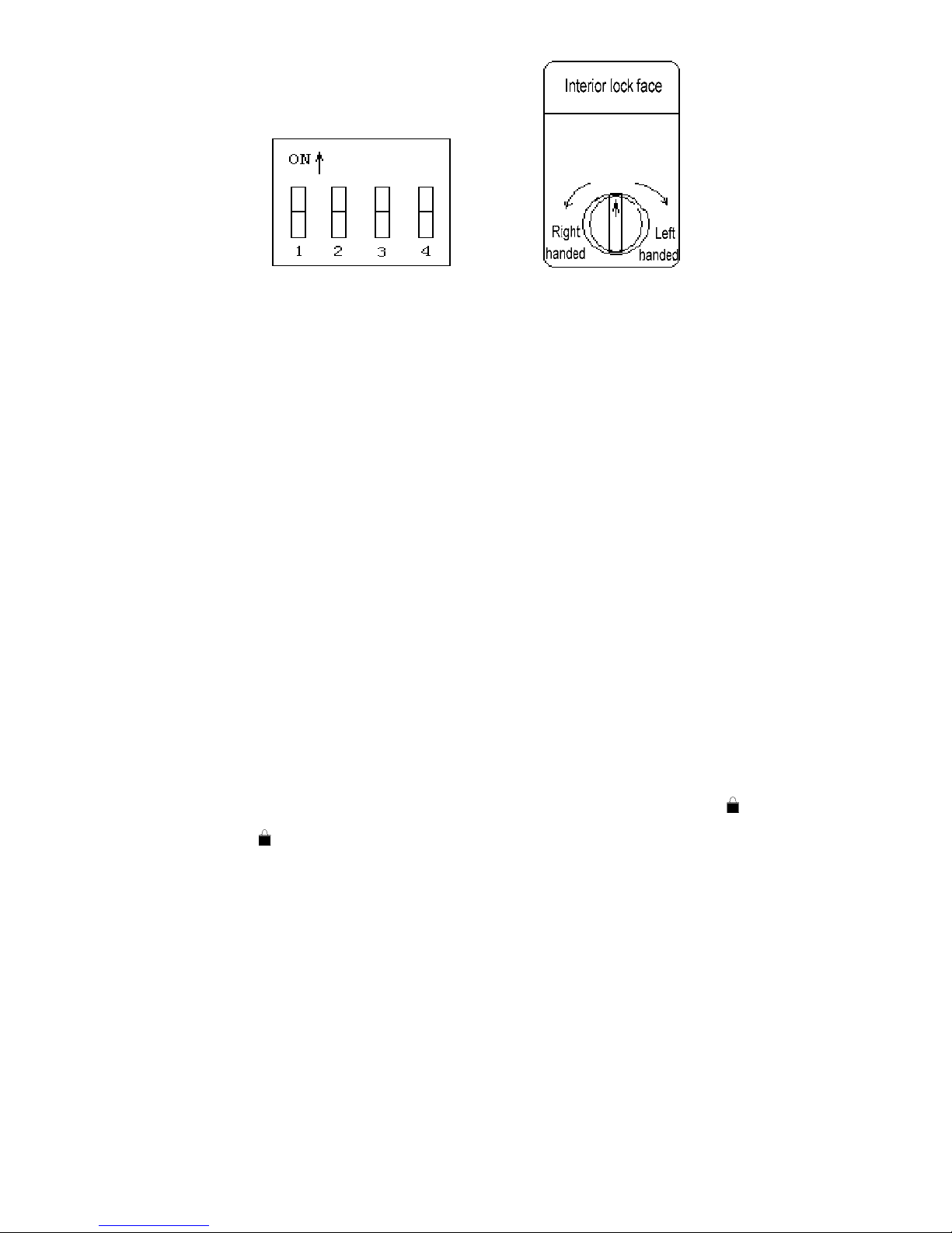
2.2.5 Dip Switch Function
Dip switch function is applicable for U20 with dip switch. Check the setting of dip switch on
the interior lock face before operation. The form below is about setting of dip switch.
Switch 1 2 3 4
Up↑Door contact locks the
door automatically (Off)
Left
handed Voice (off) Reserved
Down↓Door contact locks the
door automatically (On)
Right
handed Voice (on) Reserved
11
Diagram of dip switch Diagram of left/right handed door
Notes:
① The setting of left handed and right handed shall be consistent with the installation
position of the lock, or else, the lock can not work normally.
② The door contact can lock the door automatically only when the contact is installed.
③ Please use a ball-point pen or similar tools to toggle the switch to avoid damage to the
switch.
2.2.6 Double Lock Function
When the lock is in unlocked position, lift the lever (applicable for U30), long beep will be
heard and red LED light will flash, which means successful operation.
2.2.7 Door Contact Function
Door contact function is only applicable for U20 products that connect with door contact. If
door contact is installed and the function that door contact locks the door automatically has
been activated (refer to section 2.2.5 for details), the door can be locked automatically after
being closed. There is no need to unlock the door by pressing button . If it is not
connected, press or turn the turn piece to lock the door when the door is closed but the
lock is in unlocked position.。

12
2.3
Operation and Administration
2.3.1 Keypad Operation Method
(1) Keypad Drawing
There are six keys on the lock; they are “0”, “1”, “2”, “3”, “4” and “#”. Besides inputting
numbers, the numeric keys can also be used as the function keys .Passwords and
fingerprints can be managed by pressing the following function keys after the verification of
administration password or administration fingerprint. # is used to confirmation. For
example, you can input “1” + “#” to add new fingerprint. More details are as follow:
key function display key function display
1
Add fingerprint
1 3
Add password
3
2
Delete fingerprint
2 4
Delete password
4
(2) Password
The password consists of one digit password number and 8 digits number. You can set 5
groups of passwords and the number is P0, P1, P2, P3, P4 (P is the operational number).P0
is administration number; you can use it to delete/add other user passwords or fingerprints.
P1, P2, P3, P4 are the
default user passwords.
(3) Fingerprint Number
The maximum number of fingerprint is 100 and you can not save one fingerprint for twice.
Every fingerprint has its number and it consists of a 3digits number such as 000, 442, 321
etc. the number will display in order, e.g. 123 will be displayed as F1->23, (F mean
fingerprint). When you enroll the fingerprint you can set the fingerprint number, and every
number is just for one fingerprint. 0000 is the
default number of administration
fingerprint and other numbers are of user fingerprint.

13
2.3.2 Management of Passwords and Fingerprints
Object Procedures Phenomena (when the operation is
successful)
(1) Remove battery pack
cover.
Clear all
fingerprints (2) Press and hold fingerprint
key for 10 seconds.①
Long beep will be heard, “00” will be
displayed on the nixie tube and green LED
light will be on.
(1) Remove battery pack
cover.
(2) Press and hold password
key until you hear
the beep.
Long beep will be heard. P0 will be displayed
on the nixie tube. And then “= =” will be
displayed on the nixie tube and “= =” will
flash.
(3) Input administration
password (8 digits) “= =” will be displayed on the nixie tube
Set
administration
password
(4)Press # to confirm.
Long beep will be heard. P0 will be displayed
on the nixie tube. And green LED light will be
on.
(1) Verify administration
password②
Long beep will be heard and green LED light
will be on. P0 will be displayed on the nixie
tube.
(2) Press Key “1” “1” will be displayed on the nixie tube
(3) Press # to confirm F000 will be displayed on the nixie tube and
start the function of add fingerprint.
(4) Press # to confirm Light on the reader will be on
Enrollment of
administration
fingerprint
(5)Fingerprint acquisition○3 Long beep will be heard and green LED light
will be on.
(1) Verify administration
password or administration
fingerprint
Long beep will be heard and green LED light
will be on. P0/F000 will be displayed on the
nixie tube.
(2) Press Key “1” “1” will be displayed on the nixie tube
(3) Press # to confirm
Starting the function of add fingerprint and a
group of number will be displayed on the nixie
tube. On the other hand, you can also input
another fingerprint numbers.
(4) Press # to confirm Light on the reader will be on
Add user
fingerprint
(5)Fingerprint acquisition Long beep will be heard and green LED light
will be on.
(1) Verify administration
password or administration
fingerprint
Long beep will be heard and green LED light
will be on. P0/F000 will be displayed on the
nixie tube.
(2) Press Key “2” “2” will be displayed on the nixie tube
(3) Press # to confirm
Starting the function of delete fingerprint and
a group of number will be displayed on the
nixie tube. On the other hand, you can also
input another fingerprint numbers.
Delete user
fingerprint
(single)
(4) Press # to confirm Long beep will be heard and green LED light
will be on.

14
Object Procedures Phenomena (when the operation is
successful)
(1) Verify administration
password or administration
fingerprint
Long beep will be heard, P0/F000 will be
displayed on the nixie tube and green LED
light will be on.
(2) Press Key “3” “3” will be displayed on the nixie tube
(3) Press # to confirm
Starting the function of add password and a
group of number will be displayed on the nixie
tube. On the other hand, you can also input
another password numbers.
(4) Press # to confirm “=” will be displayed on the nixie tube
(5) Input user password (8
digits) “= =” will be displayed on the nixie tube
Add user
password
(6) Press # to confirm
Long beep will be heard and green LED light
will be on. The number just enrolled will be
displayed on the nixie tube.
(1) Verify administration
password or administration
fingerprint
Long beep will be heard and green LED light
will be on. P0/F000 will be displayed on the
nixie tube.
(2) Press Key “4” “4” will be displayed on the nixie tube
(3) Press # to confirm
Starting the function of delete password and a
group of number will be displayed on the nixie
tube. On the other hand, you can also input
another password numbers.
Delete user
password
(single)
(4) Press # to confirm
Long beep will be heard and green LED light
will be on. The number just been deleted will
be displayed on the nixie tube.
Notes:
① When clearing all fingerprints and setting the administration password /clearing the
user password, press the corresponding key and hold for 10 seconds, otherwise the system
will have no response, and the operation will fail. Before clearing the fingerprint, if there comes
low battery warning, the initialization may fail. Please replace the batteries before this
operation.
② Method to verify the administration password: input 9 digits, i.e., 1-digit password
number and 8-digit password. Please keep administration password in mind after setting of it.
③ Fingerprint acquisition method: When the light on the reader is on, put the finger on the
reader and the long beep will sound three times, it is indicate the acquisition is done. If there is
just a two short beep it means failed.
④ The administration fingerprint and the administration password can add all fingerprints
and passwords, and delete all fingerprints and password except P0. The administration
password P0 can only be changed by the settings of administration password
⑤ Only an administration fingerprint number 00 and an administration password number
P0 can be enrolled if handset is not included in operation. Other numbers are for user
15
fingerprints and user passwords, which only have the right to unlock the door. If handset is
included in operation, 3 administration password and 20 administration fingerprint can be
enrolled in maximum.
2.3.3 Unlock Ways
Unlock
ways Steps Phenomena (when the door is
successfully unlocked)
(1)Slide up the sliding cover and
press #,
①
Light on the reader and green LED light
will be on.
(2) Verify the enrolled fingerprint
Long beep will be heard, fingerprint
number will be displayed on the nixie
tube, green LED light will be on.
By
fingerprint
(3) Open the door
(1) Input the enrolled password
Password number will be displayed on
the nixie tube, green LED light will be
on and long beep will be heard.
By
password
(3)Open the door
(1) Insert mechanical key and
rotate it.
By
mechanical
key (2) Open the door
Important note:
For U20 product, you can unlock the door by turning the turn piece or pressing on the
interior lock face.
2.3.4 Right of Passwords and Fingerprints
Items Right
Administration
password
Add fingerprint and user password.
Delete all fingerprints and all passwords except for P0.
Unlock the door.
User password Unlock the door.
Administration
fingerprint
Add all fingerprints and user password.
Delete all fingerprints and all passwords except for P0.
Unlock the door.
User fingerprint Unlock the door.
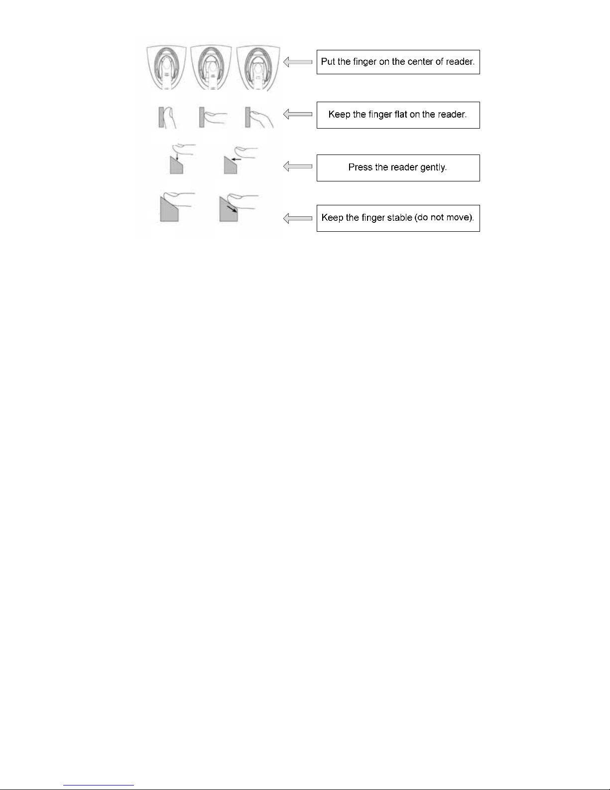
2.3.5 Points of Fingerprint Acquisition
As most information of fingerprint template comes from fingerprint center, please put the
finger in the right position during acquisition as well as verification. Method: put the finger on
the reader moderately. Refer to the following figures:
16
OK
OK
OK
OK
NO NO
NO NO
NO
N
O
2.3.6 Emergency Power Supply
In case that battery runs out and mechanical key has not been taken along, an external 9V
battery (6F22, 9V) can work as an emergency power supply. Connect it to the interface at
the bottom of the exterior assembly to supply power. And then unlock the door by fingerprint
or password.
2.3.7 Installation of Batteries
① Method to install the batteries: Remove the battery pack cover upward, and install four
AA 1.5V batteries, and then the battery pack cover.
② Notes: select the correct type in case of explosion; when out of service for a long period,
batteries should be taken out; never mix the new battery with the used; pay attention to
the positive and negative poles of batteries; preserve the environment by handing over
the used batteries to the designed place for reclaim; keep batteries out reach of
children and pets; in case of contact with skin, clothes or eyes, flush with water and go
to doctor.
17
3
Installation and Adjustment
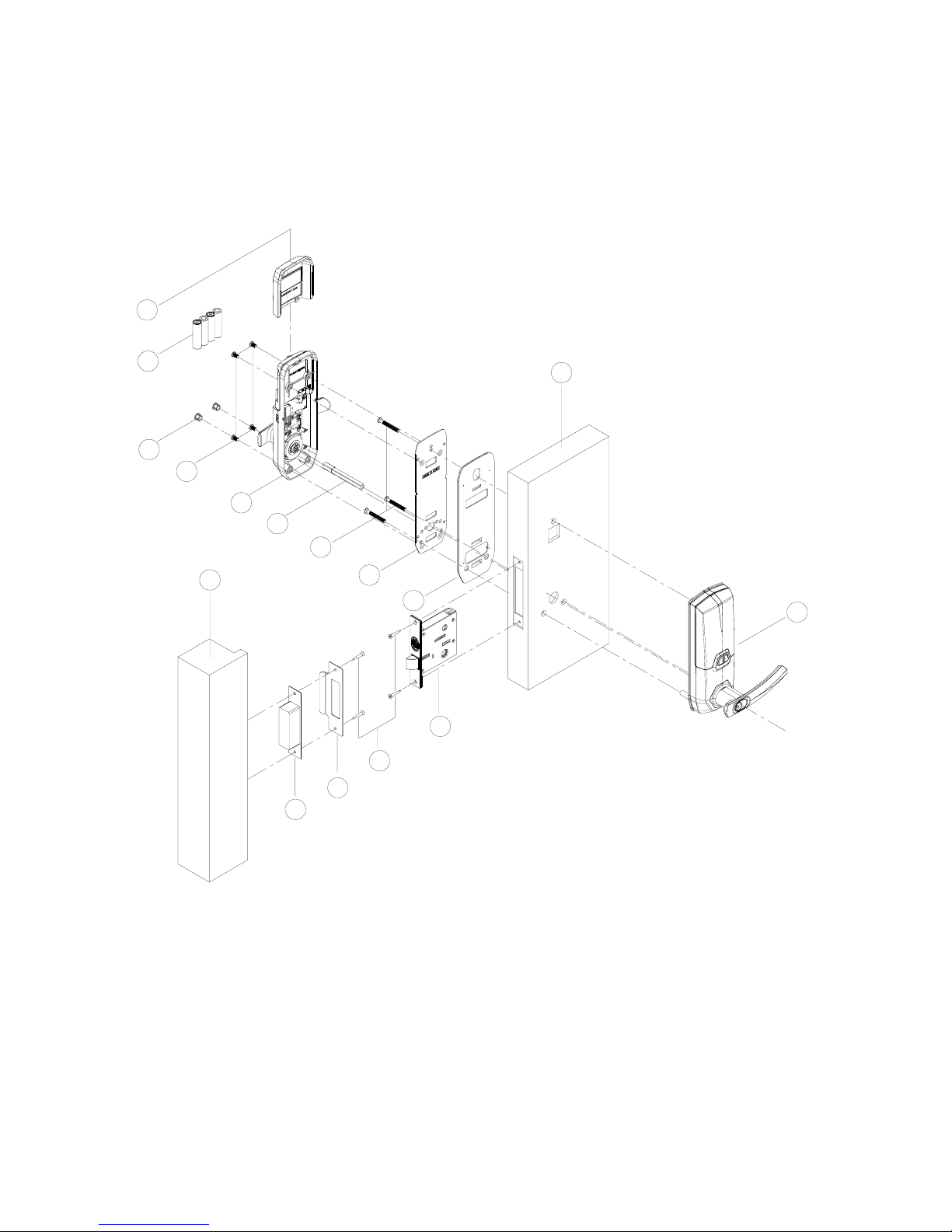
3.1
Installation Sketch
01
02
03
04
05
06
07
08
09
10
12
13
11
14
16
15
01 Battery pack cover
02 AA batteries
03 Screw cover
04 Round head flat nose metric screws
05 Interior assembly
06 Spindle
07 Cross recessed raised countersunk
head screws
08 Interior mounting plate
09 Interior shim plate
10 Countersunk flat head tapping
screws
11 Mortise
12 Exterior assembly
13 Wooden door
14 Frame
15 Striking box
16 Striking plate
18
3.2
Installation
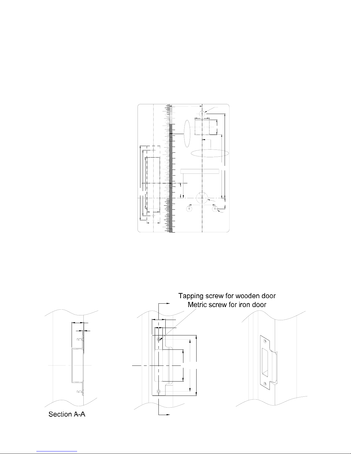
3.2.1 Step 1 Drilling Holes on the Door
This product is applicable for wooden doors. The hole pattern figure is as follows (please
follow the 1:1 template in the packing list):
The edge of door
Centerline of Lock fix
inch
cm
16
14
15
12
13
10
11
9
1
2
3
4
5
6
7
8
0
1
2
3
4
5
3
4
5
6
2
1
0
1
2
90
130.5
115
23
22
Door side center
line
26.55
Ø10
57
(UNITS:mm)
(SCALE:1:1)
Template of door lock
204020039
45
Ø10
19
Ø20
111.5
148
25
26
Centerline of handle
3.2.2 Step 2 Drilling Holes for Striking Box
As shown in figures below, process the striking hole and make sure that it is at the same
height with the lock and that it aligns with the edge of door when closed.
113
131
27
2.5 18
69
31
A
A
截面A-A
木门用自攻螺钉固定
铁门用公制螺钉固定
19
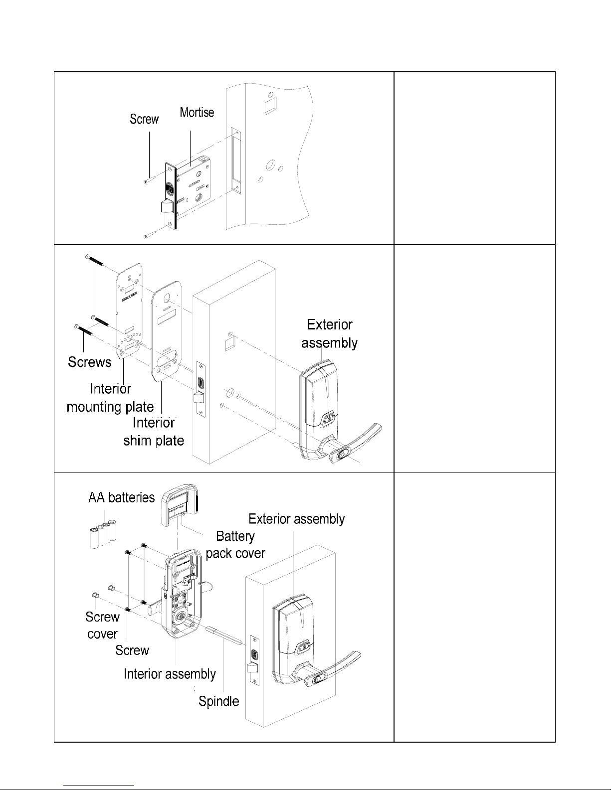
3.2.3 Step 3 Installation
门
锁芯
螺钉
(1) As shown in the figure,
insert the mortise and fix it
on the door with screws.
前锁体
门
后垫板
后盖板
螺钉
(2) As shown in the figure,
install exterior assembly,
interior shim plate and
interior mounting plate on
the door and fix them with
raised countersunk screws.
前锁体
门
大方轴
后锁体
螺
钉塞
5#电池
电池盖
螺钉
(3) As shown in the figure,
install interior assembly and
spindle on the interior
mounting plate and fix them
with screws, and install
batteries, battery pack
cover and
screw cover.
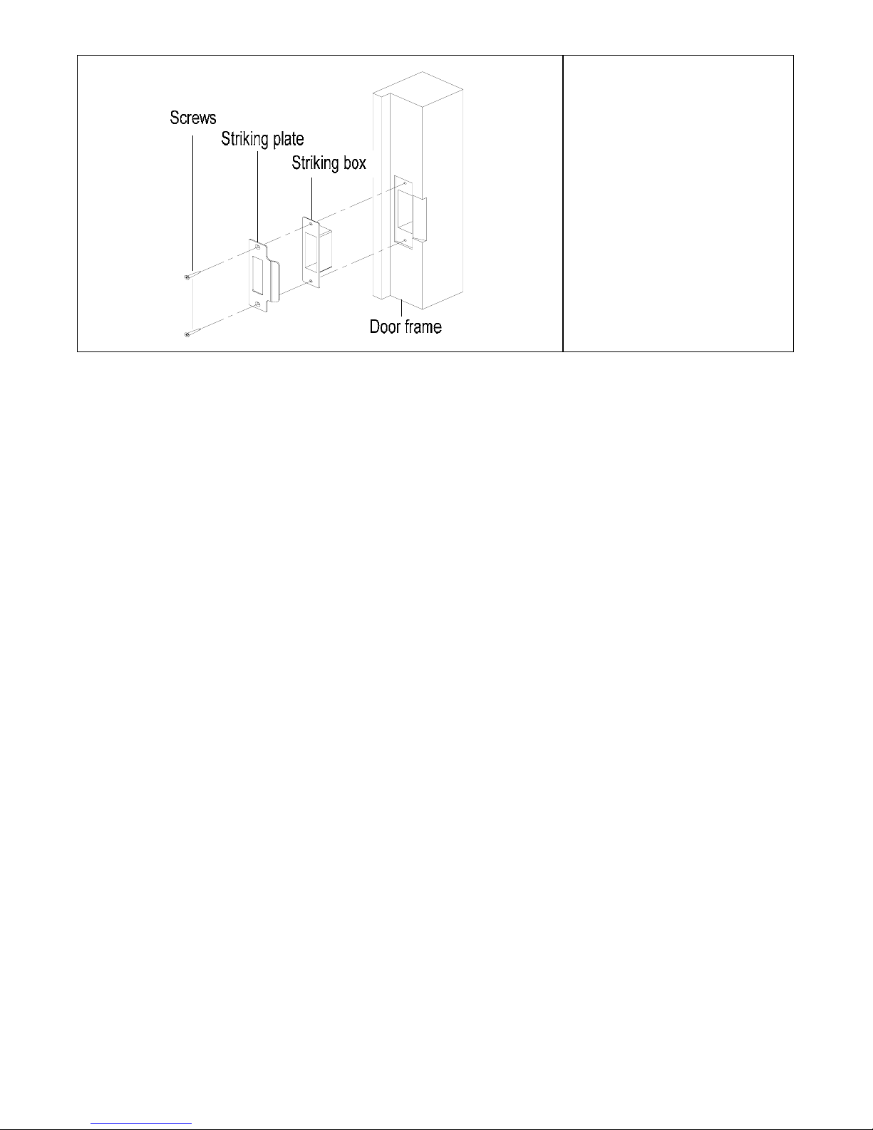
20
门框板
门框板
门扣盒
螺钉
(4) As shown in the figure,
install striking box and
striking plate on the frame
and fix them with screws.
And check the mortise at
last.
3.3
Notes for Installation
① Check the door thickness before installation whether it is within the requirements.
U10 is applicable for door thickness of 35-95mm, U20 for 35-80mm and U30 is
35-75mm
② Do not press the internal wire harness when fixing assemblies.
③ During installation, handle the lock carefully so as not to scratch the assemblies.
3.4
Adjustment
When the lock is fixed on the door, please adjust it as per Chapter 2 till the lock works well.
This manual suits for next models
2
Table of contents
Other FingerprintDoorLocks Door Lock manuals


Popular Door Lock manuals by other brands

Kwikset
Kwikset Smartcode 910 user manual

Mul-t-lock
Mul-t-lock HaspLock Diamond Installation and service instructions

Allegion
Allegion NORMBAU Fixing instructions

Schlage
Schlage L9000 Series installation instructions

INVITED
INVITED SMARTLOCK Installation guide & user manual

Itec
Itec iHTL instruction manual


