FIOR & GENTZ NEURO TRONIC User manual
2.0
NEURO TRONIC
Download: www.or-gentz.comDownload: www.or-gentz.com
EN
Instructions for Use for Orthotists or
Qualied/Trained Experts
System Knee Joint

2
EN
Content Page
Instructions for Use for Orthotists or Qualified/Trained Experts System Knee Joint NEURO TRONIC 4
1. Information 4
2. Safety Instructions 4
2.1 Classification of the Safety Instructions 4
2.2 All Instructions for a Safe Handling of the System Knee Joint 4
3. Use 7
3.1 Intended Use 7
3.2 Indication 8
3.3 Contraindication 8
3.4 Qualification 8
3.5 Application 8
3.6 Combination Possibilities with Other System Joints 8
4. Joint Functions 8
4.1 Basic Function in Auto Mode 9
4.2 Alternative Function in Lock Mode 10
4.3 Alternative Function in Free Mode 10
4.4 Alternative Function in Permanent Unlocking 10
5. NEURO TRONIC Knee Joint System 11
6. Scope of Delivery of the System Knee Joint 13
7. Load Capacity 13
8. Tools for Assembling the System Joint 13
9. Assembly Instructions 13
9.1 Mounting the Locking Parts 14
9.2 Mounting the Solenoid 14
9.3 Mounting the Cover Plate 15
9.4 Checking the System Joint's Free Movement 15
9.5 Mounting the Extension Stop Damper and the Small Cover Plate 15
9.6 Securing the Screws 15
10. Controller 16
10.1 Cable Connection of the Controller 16
11. Checking the Orthosis’ Basic Alignment 17
12. Putting into Operation 18
12.1 Putting the Expert App into Operation 18
12.2 Connection between Controller and Remote Control 18
12.3 Connection of Controller and Expert App 18
13. Adjustment Options with the Expert App 19
13.1 Selecting a Mode 19
13.2 Signal Function for Training Purposes in Auto Mode 19
13.3 Main Menu 19
13.3.1 Connecting (Putting the Controller Into Operation) 19
13.3.2 Battery Health 19
13.3.3 Cable Connection Test 19
13.3.3.1 Result Messages and Further Actions After the Cable Connection Test 20
13.3.4 Settings 20
13.3.4.1 Calibrate 20
13.3.4.2 Volume 20
13.3.4.3 Tone Selection 20
13.3.4.4 Signal Selection 20

3
13.3.4.5 Mid Stance Settings 21
13.3.4.6 Terminal Swing Settings 21
13.3.4.7 Rotation Safety 21
13.3.4.8 Motion Sensitivity 21
13.3.4.9 First Step 21
13.3.4.10 Restore to Default Settings 22
13.3.5 Step Counter 22
13.3.6 Updating the Controller and Remote Control 22
14. Connecting to the System Side Bar/System Anchor 22
15. Conversion Options 23
16. Advice on Optimal Orthosis Functionality 23
16.1 Bluetooth® Connection 23
16.2 System Knee Joint 23
16.3 Remote Control 24
16.4 Controller 24
17. Maintenance 25
17.1 Documentation of Maintenance in the Orthosis Service Passport 26
17.2 Checking the Battery Health 27
17.3 Replacing the Sliding Washers 27
17.4 Dirt Removal 27
18. Period of Use 28
19. Storage 28
20. Spare Parts 29
20.1 Exploded View Drawing NEURO TRONIC 29
20.2 Spare Parts for the NEURO TRONIC System Knee Joint 30
20.3 Sliding Washers 31
21. Disposal 31
22. Technical Data 31
22.1 Ambient Conditions 31
23. Signs and Symbols 33
24. CE Conformity 35
25. Legal Information 35
26. Electromagnetic Compatibility 36
26.1 Electromagnetic Environment 36
26.2 Electromagnetic Emissions for all Devices and Systems 36
26.3 Electromagnetic Immunity for all Devices and Systems 37
26.4 Electromagnetic Immunity for Non-Life-Supporting Devices and Systems 38
26.5 Recommended Safety Distances between Portable and Mobile
RF Telecommunication Equipment and the Product NEURO TRONIC
for Non-Life-Supporting Devices and Systems 39
26.6 Test Specifications for the Immunity of Enclosures Against Wireless
RF Telecommunication Equipment 40
27. Information for the Treatment Documentation 41
28. Handing Over the Orthosis 42
4
Instructions for Use for Orthotists or Qualified/Trained Experts System Knee Joint NEURO TRONIC
1. Information
These instructions for use are addressed to orthotists or qualified/trained experts and do not contain any notes
about dangers which are obvious to them. To achieve maximum safety, please instruct the patient and/or care
team in the use and maintenance of the product.
2. Safety Instructions
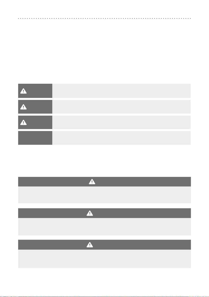
2.1 Classification of the Safety Instructions
DANGER Important information about a possible dangerous situation which, if not avoided,
leads to death or irreversible injuries.
WARNING Important information about a possible dangerous situation which, if not avoided,
leads to reversible injuries that need medical treatment.
CAUTION Important information about a possible dangerous situation which, if not avoided,
leads to light injuries that do not need medical treatment.
NOTICE Important information about a possible situation which, if not avoided, leads to
damage of the product.
All serious incidents according to Regulation (EU) 2017/745 which are related to the product have to be
reported to the manufacturer and to the competent authority of the Member State in which the orthotist or
qualified/trained expert and/or the patient is established.
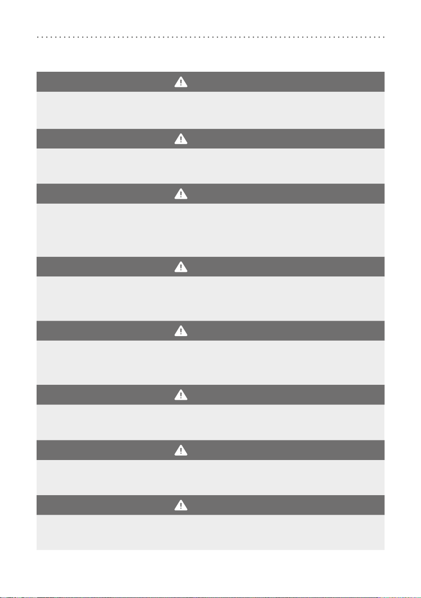
2.2 All Instructions for a Safe Handling of the System Knee Joint
DANGER
Potential Trac Accident Due to Limited Driving Ability
Advise the patient to gather information about all safety and security issues before driving a motor vehicle
with orthosis. The patient should be able to drive a motor vehicle safely.
WARNING
Jeopardising the Therapy Goal by Not Providing the Necessary Free Movement
Check if the system joint moves freely in order to avoid restrictions of the joint function. Use suitable
sliding washers according to the information in these instructions for use.
WARNING
Risk of Falling Due to Permanent Higher Load
If patient data has changed (e.g. due to weight gain, growth or increased activity), recalculate the expect-
ed load on the system joint, plan the treatment again and, if necessary, produce a new orthosis.
5
WARNING
Risk of Falling Due to Improper Processing
Process the system joint according to the information in these instructions for use. Deviating processing
and modifications of the system joint require the written consent of the manufacturer.
WARNING
Risk of Falling Due to Improper Processing
Always mount the system knee joint to an orthosis with a system ankle joint in order to avoid joint dys-
function. This also applies in case of anatomical stiening in the ankle joint.
WARNING
Risk of Falling Due to Improper Handling
Inform the patient about the correct use of the system joint and the integrated electronics, especially
with regard to excessive mechanical load (e.g. due to sports, increased activity level or weight gain), and
about not immersing the system joint in water. The electronic system components are only protected from
splashing water on all sides.
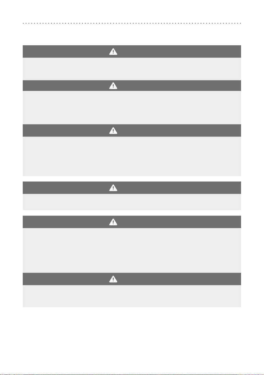
WARNING
Risk of Falling Due to Loosened Screws
Mount the cover plate to the system joint according to the assembly instructions in these instructions for
use. Secure the screws with the specified torque and the corresponding adhesive and make sure that no
sliding washers are damaged in the process.
WARNING
Risk of Falling Due to Improper Greasing of the System Joint
Only use the orthosis joint grease from the FIOR & GENTZ product range to grease the system joint. Grease
the axle bore of the toothed ring and the sliding surfaces of the bearing nut of the joint axis with just one
drop of orthosis joint grease.
WARNING
Risk of Falling Due to Incorrectly Selected System Components
Make sure that the system joint and the system components are not overloaded and are functionally
adapted to the requirements and needs of the patient in order to avoid joint dysfunction.
WARNING
Risk of Falling Due to Improper Shoe/Wrong Shoe Pitch
Advise the patient to wear a shoe to which the orthosis is adjusted in order to avoid joint dysfunction in
Auto mode.
WARNING
Risk of Falling Due to Improper Handling of the Orthosis
Make sure that the patient is able to handle their orthosis. Recommend a physiotherapeutic gait
re-education, if necessary, and explain to them the system joint’s particularities.
6
WARNING
Risk of Falling Due to Use of Unauthorised Accessories
Use only the accessories specified or supplied by the manufacturer in order to avoid increased electromag-
netic emissions and reduced electromagnetic immunity of the knee joint system.
WARNING
Risk of Falling Due to Electromagnetic Interference
Do not use the knee joint system in close proximity to or stacked with other portable RF communication
devices in order to avoid impairing the function of the knee joint system. If such use is necessary, observe
the knee joint system and other portable RF communication devices in use to ensure that they function
normally.
WARNING
Risk of Falling Due to Electromagnetic Interference
Use portable RF communication devices (including peripherals such as antenna cables and external anten-
nas) at a safety distance of at least 30cm from all components of the knee joint system to avoid impairing
the function of the knee joint system. If use at a distance of less than 30cm is necessary, observe the knee
joint system during use to ensure that it functions normally. Also note the safety distances for RF commu-
nication devices specified in these instructions for use (see paragraph 26.5).
WARNING
Risk of Electric Shock Due to Improper Handling
Only use the supplied accessories to avoid electric shock and damage to the knee joint system.
WARNING
Risk of Injury Due to Improper Handling of the Controller or Remote Control
Use the controller and the remote control as described in these instructions for use. The controller is a
sensitive electronic device with an integrated lithium-polymer battery. Pay particular attention to:
- not wearing the orthosis during the battery charging process,
- avoiding contact with strong heat or fire,
- not charging the controller under direct sunlight, and
- not opening the controller or the remote control.
WARNING
Risk of Injury Due to Improper Handling of the System Joint
When using the system joint, an opening is formed between the joint’s upper and lower part, in which
clothing or skin could get caught. Please inform the patient of this risk.

7
WARNING
Damage to the Anatomical Joint Due to Incorrect Position of the Joint’s Mechanical Pivot Point
Determine the joint’s mechanical pivot points correctly in order to avoid a permanent incorrect load on the
anatomical joint. Please refer to the online tutorials on our website or contact Technical Support.
NOTICE
Limitation of the Joint Function Due to Improper Processing
Errors in processing can impair the joint function. Pay particular attention to:
- correctly connect the system side bar/system anchor with the system case in accordance with the pro-
duction technique;
- not tempering the orthosis when the functional unit and controller are mounted,
- grease the joint components only slightly and
- adhere to the maintenance intervals.
NOTICE
Limitation of the Joint Function Due to Improper Dirt Removal
Inform the patient on how to properly remove dirt from the orthosis and the system joint.
NOTICE
Limitation of the Joint Function Due to Lack of Maintenance
Respect the specified maintenance intervals in order to avoid joint dysfunction. Inform the patient about
the maintenance appointments to be respected. Enter the next maintenance appointment in the orthosis
service passport of the patient.
NOTICE
Damage to Controller Due to Improper Handling
Use the controller as described in these instructions for use. In particular, please ensure that the controller:
- is used only with the provided charging cable and adapter, and
- is only used at ambient temperatures from -10°C to +40°C.
3. Use
3.1 Intended Use
The NEURO TRONIC knee joint system with component set, including system knee joint and controller, is ex-
clusively for use for orthotic fittings of the lower extremity. The system joint provides stance phase control and
is only allowed to be used for producing a KAFO. Every system joint influences the orthosis’ function and thus
also the function of the leg. The system joint may only be used for one fitting and must not be reused.
Advise the patient to contact the manufacturer in case of problems with the system joint and poten-
tially occurring allergic reactions. You can find the manufacturer’s contact data on the back page of
these instructions for use.

8
The knee joint system is equipped with Bluetooth® technology. With the Expert app you can adjust orthoses
that are equipped with the NEURO TRONIC system knee joint.
3.2 Indication
The indications for the treatment with an orthosis for the lower extremity are insecurities that lead to a
pathological gait. This can be caused, for example, by central, peripheral, spinal or neuromuscular paralyses,
structurally conditioned deformities/malfunctions or surgery.
The physical conditions of the patient, such as muscle strength or activity level, are crucial for the orthotic
treatment. An evaluation regarding the safe handling of the orthosis by the patient must be carried out.
3.3 Contraindication
The system joint is not suitable for treatments that were not described in paragraph 3.2, such as a treatment
of the upper extremity or a treatment with a prosthesis or ortho-prosthesis, for example after amputations of
leg segments.
3.4 Qualification
The system joint must only be handled by an orthotist or a qualified/trained expert.
3.5 Application
All FIOR & GENTZ system joints were developed for everyday life activities such as standing and walking.
Extreme impact stress, which occurs for example during long jump, climbing and parachuting, is excluded. The
system joint can be used at temperatures of -10°C to +40°C.
3.6 Combination Possibilities with Other System Joints
The NEURO TRONIC system knee joint must be combined with a system ankle joint from the FIOR &GENTZ
product range. The NEURO VARIO system knee joint can be used as a supporting joint.
We recommend that you use the Orthosis Configurator when selecting all system components for your orthosis
and follow the recommendations of the configuration result.
4. Joint Functions
The NEURO TRONIC is a microprocessor-controlled, automatic system knee joint that provides four joint
functions:
- basic function in delivery status in Auto mode
- alternative function in Lock mode
- alternative function in Free mode
- alternative function in permanent unlocking
9
The essential performance features of the automatic electronic system joint are to remain unlocked in Free
mode and locked in Lock mode, as well as to lock or unlock at the right moment in Auto mode.
The system knee joint is preassembled at an angle of 5°, corresponding to a physiological knee joint angle. By
exchanging the 5° joint’s upper part for a 0° or a 10° joint’s upper part, the joint angle can be changed by 5°
in the direction of flexion or extension.
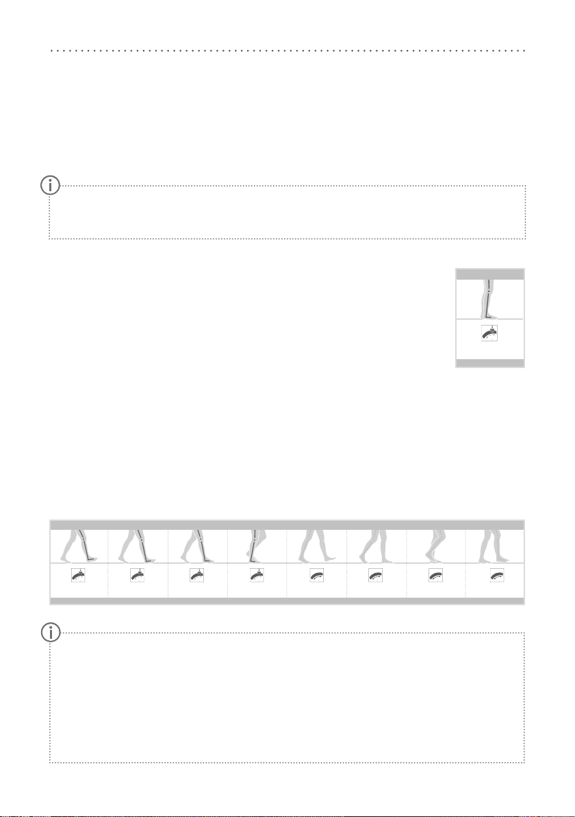
4.1 Basic Function in Auto Mode
The controller of the orthosis has motion sensors which detect the movement and position
of the lower leg. Thus, the controller can lock/unlock the system joint in the respective gait
phases.
Stance
When the patient is standing with the orthosis (fig. 1) or when they do not finish their step
in stance phase, the system knee joint locks, as no movement is registered.
Gait
When walking, the system joint locks/unlocks as follows: the system joint is locked in the direction of flexion
from terminal swing to mid stance (fig. 2). The solenoid shuts off and the coil spring pushes the plunger up-
wards, which causes the locking pawl to mesh into the toothing of the toothed ring (fig. 3).
In the gait phases from terminal stance to mid swing, the system joint is unlocked and is therefore free moving
(fig.2). The solenoid turns on and generates an electromagnetic field, which causes the plunger to retract
magnetically against the spring force, while gravity causes the locking pawl to fall downwards from the tooth-
ing of the toothed ring (fig. 4).
The locking/unlocking moment can be fine adjusted with the Expert app.
In the free moving phases terminal stance and pre swing, the system knee joint is not secured elec-
tronically in order to prepare the knee flexion for pre swing:
- In terminal stance, securing against knee flexion takes place via the levering back extension moment
of the forefoot lever.
- If, contrary to expectations, weight is put on the leg with orthosis in pre swing when the step is
interrupted in this phase, the system joint will not lock. Explain this situation to the patient and, if
necessary, train with them.
If one of the free moving phases initial swing or mid swing is unexpectedly interrupted, the system
joint will lock safely.
If electromagnetic interference occurs, the automatic knee joint system does not function as described
in these instructions for use. Read the safety instructions before using the knee joint system to avoid
problems.
初期接地 荷重応答期 立脚中期 立脚終期 前遊脚期 遊脚初期遊脚終期
ロック ロック ロック ロック
遊脚中期
自由運動 自由運動 自由運動 自由運動
NEURO TRONIC:関節に関係する歩行段階
JA
立脚
ロック
立位
Initial contact Loading response Mid stance Terminal stance Pre swing Initial swingTerminal swing
Låst Låst Låst Låst
Mid swing
Fritt bevegelig Fritt bevegelig Fritt bevegelig Fritt bevegelig
NEURO TRONIC: LEDDRELEVANTE GANGFASER
NO
Stand
Låst
STÅENDE
Initial contact Loading response Mid stance Terminal stance Pre swing Initial swingTerminal swing
vergrendeld vergrendeld vergrendeld vergrendeld
Mid swing
vrij beweeglijk vrij beweeglijk vrij beweeglijk vrij beweeglijk
NEURO TRONIC: GEWRICHTSRELEVANTE GANGFASEN
NL
Standfase
vergrendeld
BIJ STILSTAAN
Initial contact Loading response Mid stance Terminal stance Pre swing Initial swingTerminal swing
Bloqueada Bloqueada Bloqueada Bloqueada
Mid swing
De movimiento libre De movimiento libre De movimiento libre De movimiento libre
NEURO TRONIC: FASES DE LA MARCHA RELEVANTES PARA LA ARTICULACIÓN
ES
Fase de apoyo
Bloqueada
DE PIE
Initial contact Loading response Mid stance Terminal stance Pre swing Initial swingTerminal swing
bloccata bloccata bloccata bloccata
Mid swing
libertà di movimento libertà di movimento libertà di movimento libertà di movimento
NEURO TRONIC: FASI DI DEAMBULAZIONE RILEVANTI PER L‘ARTICOLAZIONE
IT
Fase d‘appoggio
bloccata
IN POSIZIONE ERETTA
Initial contact Loading response Mid stance Terminal stance Pre swing Initial swingTerminal swing
Verrouillée Verrouillée Verrouillée Verrouillée
Mid swing
À mouvement libre À mouvement libre À mouvement libre À mouvement libre
NEURO TRONIC: PHASES DE MARCHE ESSENTIELLES POUR L‘ARTICULATION
FR
Phase d‘appui
Verrouillée
DEBOUT
Initial contact Loading response Mid stance Terminal stance Pre swing Initial swingTerminal swing
locked locked locked locked
Mid swing
free moving free moving free moving free moving
NEURO TRONIC: JOINT RELEVANT GAIT PHASES
EN
Stance
locked
STANDING
Initial contact Loading response Mid stance Terminal stance Pre swing Initial swingTerminal swing
gesperrt gesperrt gesperrt gesperrt
Mid swing
frei beweglich frei beweglich frei beweglich frei beweglich
NEURO TRONIC: GELENKRELEVANTE GANGPHASEN
DE
Stand
gesperrt
IM STEHEN
fig. 1
fig. 2
初期接地 荷重応答期 立脚中期 立脚終期 前遊脚期 遊脚初期遊脚終期
ロック ロック ロック ロック
遊脚中期
自由運動 自由運動 自由運動 自由運動
NEURO TRONIC:関節に関係する歩行段階
JA
立脚
ロック
立位
Initial contact Loading response Mid stance Terminal stance Pre swing Initial swingTerminal swing
Låst Låst Låst Låst
Mid swing
Fritt bevegelig Fritt bevegelig Fritt bevegelig Fritt bevegelig
NEURO TRONIC: LEDDRELEVANTE GANGFASER
NO
Stand
Låst
STÅENDE
Initial contact Loading response Mid stance Terminal stance Pre swing Initial swingTerminal swing
vergrendeld vergrendeld vergrendeld vergrendeld
Mid swing
vrij beweeglijk vrij beweeglijk vrij beweeglijk vrij beweeglijk
NEURO TRONIC: GEWRICHTSRELEVANTE GANGFASEN
NL
Standfase
vergrendeld
BIJ STILSTAAN
Initial contact Loading response Mid stance Terminal stance Pre swing Initial swingTerminal swing
Bloqueada Bloqueada Bloqueada Bloqueada
Mid swing
De movimiento libre De movimiento libre De movimiento libre De movimiento libre
NEURO TRONIC: FASES DE LA MARCHA RELEVANTES PARA LA ARTICULACIÓN
ES
Fase de apoyo
Bloqueada
DE PIE
Initial contact Loading response Mid stance Terminal stance Pre swing Initial swingTerminal swing
bloccata bloccata bloccata bloccata
Mid swing
libertà di movimento libertà di movimento libertà di movimento libertà di movimento
NEURO TRONIC: FASI DI DEAMBULAZIONE RILEVANTI PER L‘ARTICOLAZIONE
IT
Fase d‘appoggio
bloccata
IN POSIZIONE ERETTA
Initial contact Loading response Mid stance Terminal stance Pre swing Initial swingTerminal swing
Verrouillée Verrouillée Verrouillée Verrouillée
Mid swing
À mouvement libre À mouvement libre À mouvement libre À mouvement libre
NEURO TRONIC: PHASES DE MARCHE ESSENTIELLES POUR L‘ARTICULATION
FR
Phase d‘appui
Verrouillée
DEBOUT
Initial contact Loading response Mid stance Terminal stance Pre swing Initial swingTerminal swing
locked locked locked locked
Mid swing
free moving free moving free moving free moving
NEURO TRONIC: JOINT RELEVANT GAIT PHASES
EN
Stance
locked
STANDING
Initial contact Loading response Mid stance Terminal stance Pre swing Initial swingTerminal swing
gesperrt gesperrt gesperrt gesperrt
Mid swing
frei beweglich frei beweglich frei beweglich frei beweglich
NEURO TRONIC: GELENKRELEVANTE GANGPHASEN
DE
Stand
gesperrt
IM STEHEN
10
4.2 Alternative Function in Lock Mode
In Lock mode, the NEURO TRONIC is a
locked system knee joint that is permanently
mechanically locked in a determined extension
position.
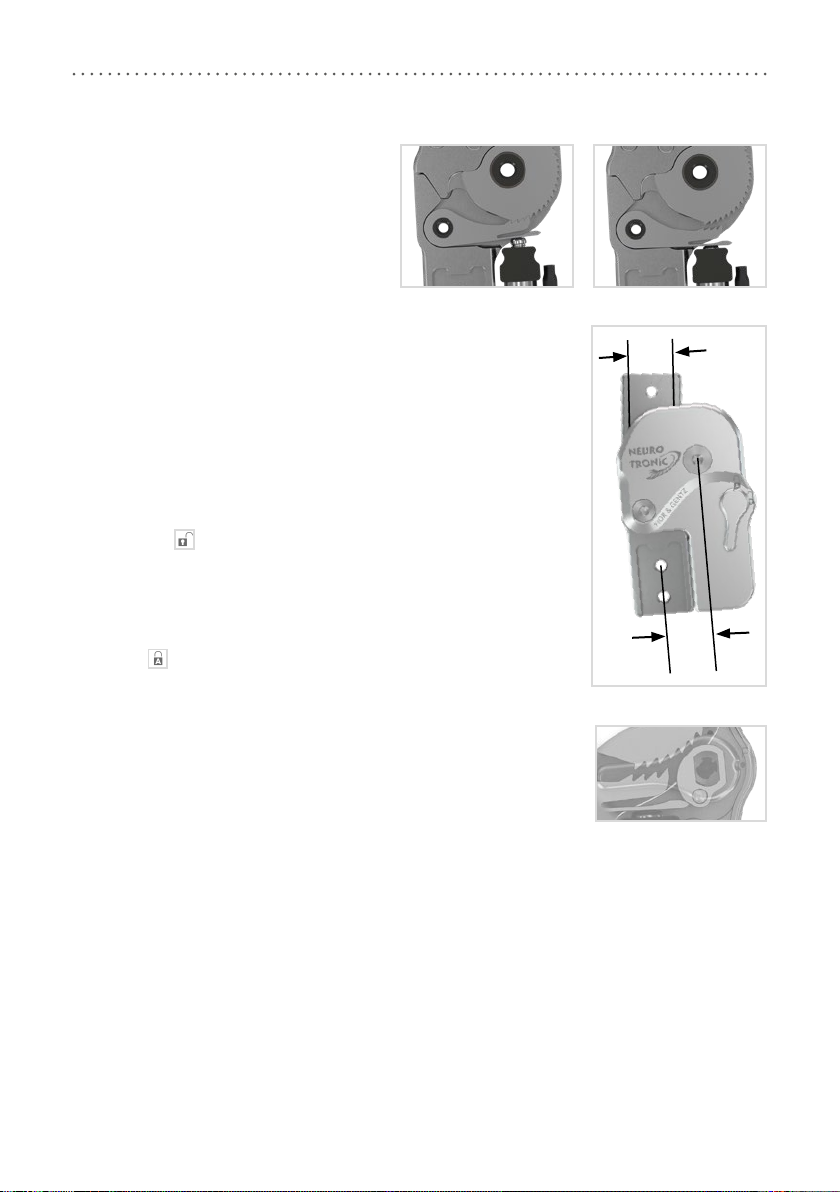
4.3 Alternative Function in Free Mode
In Free mode, the NEURO TRONIC system knee joint is unlocked and free
moving up to a defined extension position. When the patient is standing with
the orthosis, the stance phase control is achieved by means of the integrated
posterior oset (fig. 5) and the patient’s remaining function of the knee and hip
extension muscles.
4.4 Alternative Function in Permanent Unlocking
The NEURO TRONIC system knee joint can be permanently unlocked mechani-
cally with a lever, for example for activities such as driving a car or riding a
bicycle. In this mode it is guaranteed that the system knee joint does not lock
unintentionally. To do so, unlock the system joint manually with the lever by
setting it to the symbol.
In order to save energy, you can then press the Lock button with the remote
control/User app. The system knee joint also remains unlocked if you select
another mode (e.g. Auto) with the remote control/app since the lever blocks the
locking pawl, which, therefore, cannot mesh into the toothing (fig. 6). In order
to change the system joint’s mode again with the remote control/app, set the
lever to the symbol (fig.5).
fig. 3 fig. 4
fig. 5
posterior
oset
=
system
width
system
width
fig. 6
11
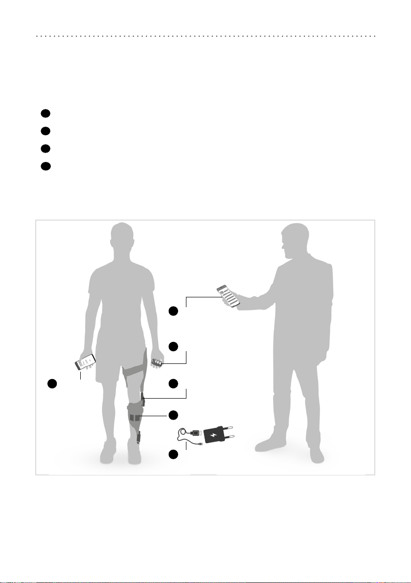
5. NEURO TRONIC Knee Joint System
The knee joint system is equipped with Bluetooth® technology* and consists of the following components
(fig.7):
1system knee joint
2controller
3remote control for the patient including charging cable with adapter and User app
4Expert app for the orthotist or qualified/trained expert
The system knee joint and the controller are built into the patient's orthosis. In order to put the orthosis into
operation and adjust it, you need the Expert app. The app has to be unlocked once from the login area on the
FIOR &GENTZ website. The patient needs the remote control to operate the orthosis. As a complement, the
User app can be used.
* The Bluetooth® word mark and logos are registered trademarks of Bluetooth SIG, Inc. and any use of such
marks by FIOR&GENTZ is under license.
fig. 7
PATIENT
controller
2
system knee joint
1
ORTHOTIST
4Expert app
3User app
charging cable
and adapter
3
remote control
3
12
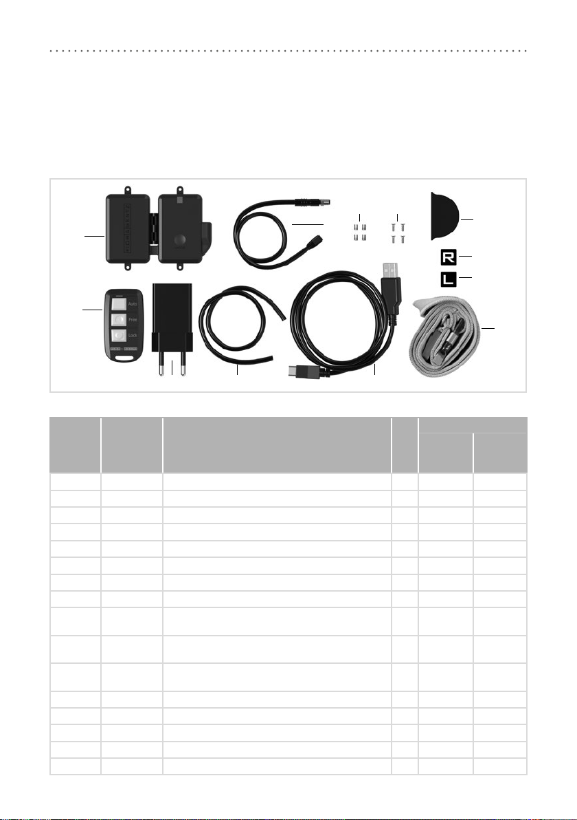
In order to produce a KAFO with the NEURO TRONIC system knee joint, you need a component set which
must be purchased as an accessory to the system knee joint. Select the unilateral or bilateral component set
depending on the construction. Both sets include only one controller. A second controller is not required for
bilateral constructions. Please note that you must order the lamination dummy for the controller and the lam-
ination dummy for the wye junction of the solenoid connection cable separately. These can be used multiple
times. The scope of delivery of a set includes the following system components (fig. 8):
Item Article No. Description Unit
Quantity
Compo-
nent Set
Unilateral
Compo-
nent Set
Bilateral
1 ET3850 controller with lithium-polymer battery pce. 1 1
2 ET0712-01
connection cable for solenoid, unilateral, 300mm
pce. 1 -
2 ET0712-02 connection cable for solenoid, bilateral, 420mm pce. - 1
3 VE0831-A3 thread insert pce. 4 4
4 SC1302-L06 countersunk flat head screw, cross recessed H pce. 4 4
5 ET0971-1 lamination dummy for cable length compensation pce. 1 2
6 ET3840-P remote control pce. 1 1
7 ET0780 adapter pce. 1 1
8 SK0935-11 lamination dummy for solenoid connection cable,
250mm pce. 1 1
8 SK0935-12 lamination dummy for solenoid connection cable,
170mm pce. - 1
8 SK0935-13 lamination dummy for solenoid connection cable,
85mm pce. - 1
9 ET0710-01 charging cable pce. 1 1
10 PR4000 lanyard FIOR &GENTZ pce. 1 1
11 HE3800-SK/L letter sticker L for remote control, left leg pce. 1 1
12 HE3800-SK/R letter sticker R for remote control, right leg pce. 1 1
w/o fig. OB1000-XL cloth bag for orthoses with logo pce. 1 1
fig. 8
5
9
78
1
6
2
34
10
11
12
13
You can find more information on special work steps that must be observed when building
an orthosis with the NEURO TRONIC system knee joint, such as the placement of dummies
as well as the specifics of reinforcement, in the corresponding online tutorial (see QR code,
fig. 9) on the FIOR &GENTZ website.
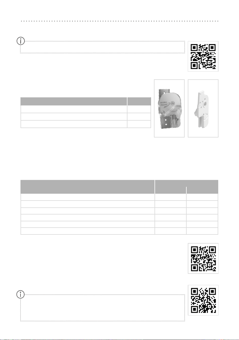
6. Scope of Delivery of the System Knee Joint
Description Quantity
NEURO TRONIC system knee joint (fig. 10) 1
assembly/lamination dummy (fig. 11) 1
orthosis joint grease, 3g (without figure) 1
7. Load Capacity
The load capacity results from the relevant patient data and can be determined by using the Orthosis
Configurator. We recommend that you use the system components determined by the Orthosis Configurator
when producing an orthosis and mind the recommended production technique.
8. Tools for Assembling the System Joint
Tools
System Width
16mm 20mm
T8 hexalobular screwdriver/bit x x
T15 hexalobular screwdriver/bit x -
T20 hexalobular screwdriver/bit x x
torque screwdriver, 1–6Nm x x
twist drill, 3.2mm x x
PH0 cross-recessed screwdriver x x
9. Assembly Instructions
The system joint is delivered fully assembled. All functions are checked beforehand. You
have to disassemble the system joint for mounting it in the orthosis and for maintenance.
To ensure an optimal functioning, follow the assembly instructions below. Secure all screws
with the torque specified in paragraph 9.6.
You can find more information on the assembly in the online tutorial Joint Assembly
NEURO TRONIC (see QR code, fig. 12) on the FIOR &GENTZ website.
When mounting the system joint, mind the correct basic alignment of the orthosis
as it is essential for the later function of the orthosis. You can find more information
on this in the online tutorial KAFO Alignment Guidelines (see QR code, fig. 13) on
the FIOR &GENTZ website.
Please note that the charging cable and adapter are not a part of the medical device.
fig. 9
fig. 10 fig. 11
fig. 12
fig. 13
14
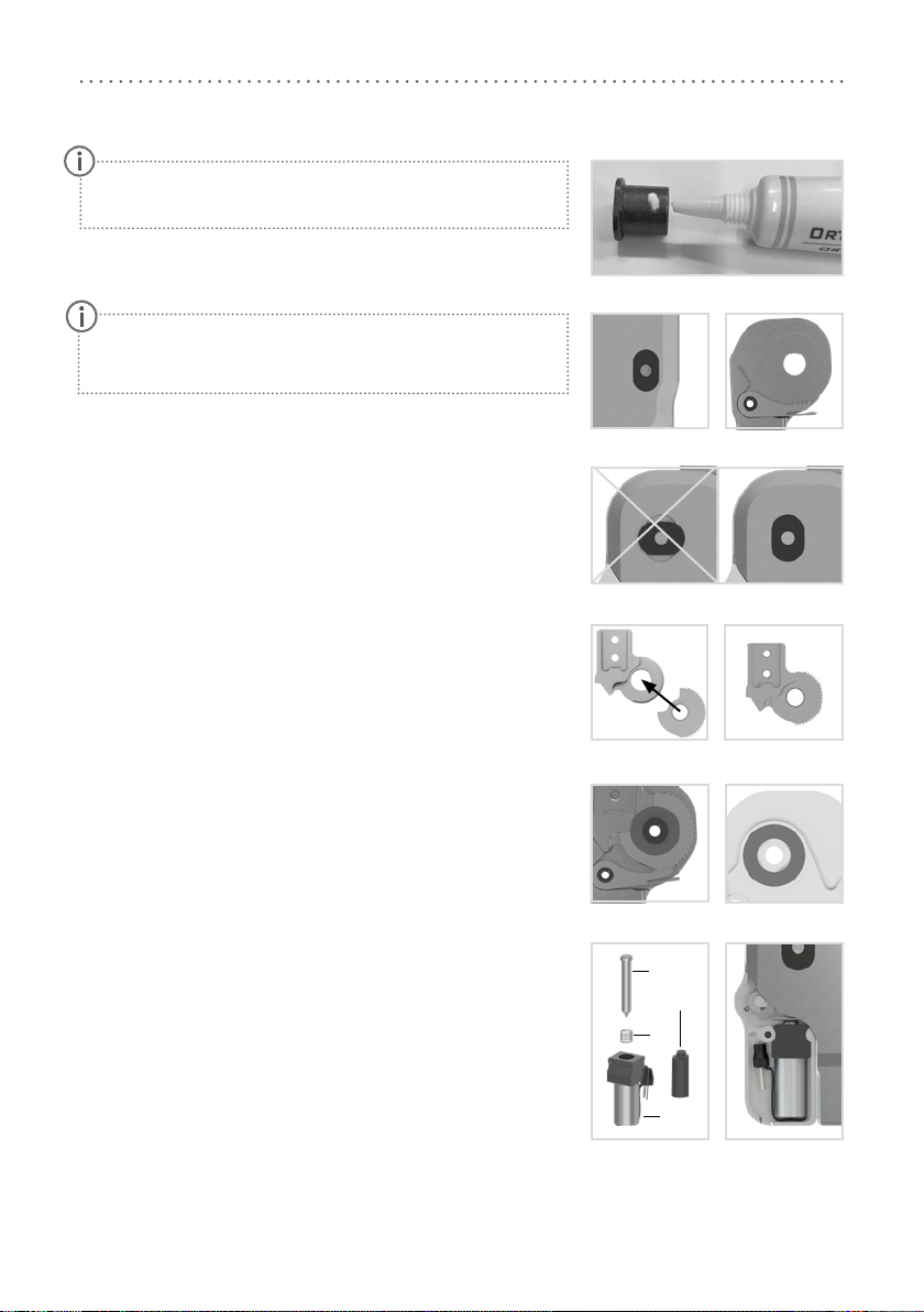
9.1 Mounting the Locking Parts
1 Grease the axle bore of the toothed ring and the sliding surfaces
of the bearing nut of the joint axis with a drop of orthosis joint
grease (fig. 14). Make sure that no grease enters the toothing of
the locking pawl and the toothed ring.
2 Put the bearing nut for the locking pawl into the opening of the
joint’s lower part (fig. 15).
3 Mount the locking pawl (fig. 16).
4 Insert the bearing nut for the joint axis into the opening of the
joint’s lower part (fig. 17).
5 Grease the first sliding washer slightly on both sides with orthosis
joint grease and place it on the joint's lower part.
6 Place the toothed ring on the front side of the joint's upper part so
that it is flush with the joint’s upper part. The wavy cut-out has to
point in direction of the joint's upper part (fig. 18–19).
7 Mount the joint’s upper part (fig. 20). Make sure that the joint’s
upper part is placed without play.
8 Apply spray adhesive on one side of the second sliding washer and
adhere it to the cover plate (fig. 21).
9 Grease the other side slightly with orthosis joint grease.
9.2 Mounting the Solenoid
1 Place the coil spring (2; fig. 22) onto the plunger (1).
2 Slide the plunger into the solenoid (3).
3 Secure the solenoid by pressing it into the cover plate (fig. 23).
Make sure not to damage the sliding washer during assembly.
Jammed sliding washer particles can cause lateral play in the
system joint.
Only use the FIOR &GENTZ orthosis joint grease to grease the
system components.
fig. 14
fig. 15 fig. 16
fig. 17
fig. 18 fig. 19
fig. 20 fig. 21
fig. 22
1
2
3
4
fig. 23
15
The screws for the cover plate are not secured with the necessary torque at delivery. You can also find
information on the torque in the openings of the cover plate.
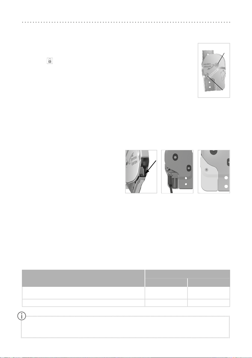
9.3 Mounting the Cover Plate
The lever of the cover plate is already premounted. For the following steps, the lever must
be set to the symbol.
1 Before the assembly, clean the threads of the bearing nuts with LOCTITE®7063 Super
Clean. Allow the threads to air-dry for 10 minutes.
2 Place the cover plate on the system joint.
3 Screw in the first countersunk flat head screw (axle screw, S1; fig. 24).
4 Screw in the second countersunk flat head screw (S2; fig. 24).
9.4 Checking the System Joint's Free Movement
Tighten the screws for the cover plate with the appropriate torque (see paragraph 9.6). Check if the system
joint moves freely. If the system joint runs with lateral play, mount the next thicker sliding washer. If it does
not move freely (it is jammed), mount the next thinner sliding washer.
9.5 Mounting the Extension Stop Damper and the Small Cover Plate
1 Turn the system joint upside down and place the
extension stop damper into the bore (fig. 25).
2 Bring the system joint in extension.
3 Lay the cable for the solenoid (fig. 26).
4 Connect the cable to the solenoid port.
5 Place the end cap (4; fig. 22) over the connec-
tion.
6 Mount the small cover plate onto the back of
the system joint (fig. 27).
9.6 Securing the Screws
The screws are secured after the orthosis has been produced and tried on and before it is handed over to the
patient.
1 Loosen the screws for the cover plate (fig. 24) after checking the system joint's free movement and remove
them from the cover plate.
2 Apply a small drop of LOCTITE® 243 medium strength to the thread of the screws.
3 Secure the screws for the cover plate (fig. 24) with the torque corresponding to the system width.
4 Let the adhesive harden (final strength after approx. 24 hours).
Screws for Cover Plate
System Width
16mm 20mm
countersunk flat head screw with hexalobular socket
(axle screw, S1) 4Nm 4Nm
countersunk flat head screw with hexalobular socket (S2) 3Nm 4Nm
fig. 24
S1
S2
fig. 25 fig. 26 fig. 27
16
10. Controller
The controller is delivered with the component set and is mounted onto the orthosis. It receives adjustments
from the Expert app and commands from the remote control/User app, registers the patient’s movements and
controls the NEURO TRONIC system knee joint.
The controller can be used for a unilateral as well as a bilateral construction. It automatically recognises
whether one or two system knee joints are connected to the controller.
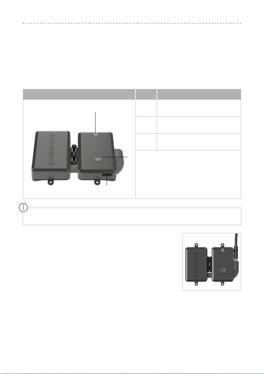
Controller with Integrated Lithium-Polymer Battery Item Description
1multicolour LED for battery charging,
mode and Bluetooth connection
2 MODE button
3 charging connection
10.1 Cable Connection of the Controller
Before you mount the controller onto the orthosis, you must establish a con-
nection to the solenoid of the system knee joint via a connecting cable.
1 Plug the connecting cable into the port on the controller (fig.28).
2 Tighten the knurled threaded bushing of the connection cable.
3 Secure the controller to the orthosis shell using the accompanying coun-
tersunk flat head screws.
For more information on mounting the controller to the orthosis, refer to the online tutorials on the
FIOR &GENTZ website.
2
3
1
fig. 28

17
11. Checking the Orthosis’ Basic Alignment
Make sure that the orthosis’ alignment is correct before putting the orthosis into opera-
tion. You can then make further adjustments to the orthosis using the Expert app. You can
find more information on the correct orthosis’ alignment in the online tutorial Checking
the Orthosis’ Alignment – Dynamically (see QR code, fig. 29) and Checking the Orthosis’
Alignment – Statically (see QR code, fig. 30) on the FIOR &GENTZ website, or on our
YouTube channel.
On the Workbench
Regardless of the plantar flexion, automatic system knee joints require a systematic ad-
justment of the dorsiflexion stop for an optimal function of the orthosis. The dorsiflexion
stop determines the moment the system knee joint unlocks during mid stance. Further-
more, it leads to an extension moment which is applied to the orthosis and the system
knee joint, which is necessary to unlock the system knee joint.
Fix the foot piece of the orthosis firmly in the patient's shoe and put the orthosis on the
workbench. The dorsiflexion stop of the system ankle joint must be adjusted in such a way that the line of
gravity passes through the middle of the thigh shell and runs vertically downwards in front of the system
ankle joint and between the ankle’s pivot point and the rolling-o line.
Statically on the Patient
For checking the correct static alignment of the orthosis, the patient must wear the orthosis and stand upright
with parallel feet. When viewed from the side, the line of gravity must run from the body's centre of gravity
vertically downwards in front of the system ankle joint and between the ankle’s pivot point and the rolling-o
line. The course of the line of gravity at knee height results from the individual normal posture. Wearing the
orthosis leads to deformation of soft tissue. This deformation causes the line of gravity to shift forward. Please
consider this by readjusting the dorsiflexion stop, if necessary.
If the dorsiflexion stop is adjusted correctly, a lever is formed between the forefoot and lower leg (activation
of the forefoot lever) which brings the patient into a stable balance (they are able to balance themselves) and
applies the necessary knee extension moment.
Dynamically on the Patient
For checking the correct dynamic alignment of the orthosis, the patient must wear the orthosis and walk a
few steps with it. The dorsiflexion stop must be adjusted in such a way that a heel lift can clearly be seen in
terminal stance. The consequence is a lever between forefoot and lower leg which brings the patient into a
stable balance and applies the necessary knee extension moment. If the heel does not lift, you must reduce the
system ankle joint's range of motion in dorsiflexion.
fig. 29
fig. 30
18
12. Putting into Operation
12.1 Putting the Expert App into Operation
Download the app with your smartphone/tablet. Minimum requirements are Bluetooth 4.0
and Android 6.0 or iOS 10. Unlock the app once from the login area on the FIOR &GENTZ
website. This ensures that patients cannot access the Expert app and change the orthosis’
settings.
12.2 Connection between Controller and Remote Control
In order to connect the remote control to the controller, proceed as follows:
1 Press the MODE button on the controller. First, a short beep is emitted. Press and hold the button until a
second, longer beep is emitted after about 6–10 seconds.
2 Press the Auto and Lock button of the remote control at the same time for about four seconds. The LED
blinks orange.
If the connection to the controller has been successful, the LED on the remote control blinks green. If estab-
lishing the connection has failed, it blinks red.
The remote control can also be connected to two controllers:
1 Press the MODE button on both controllers. First, a short beep is emitted. Press and hold the buttons until a
second, longer beep is emitted after about 6–10 seconds.
2 Press the Auto and Lock buttons of the remote control at the same time for about four seconds. The LEDs
light up.
If the connection to both controllers has been successful, the LED on the remote control blinks green twice. If
the LED on the remote control blinks green only once, the remote control is only connected to one controller.
In this case, repeat steps 1–2. If establishing the connection has failed, the LED blinks red.
12.3 Connection of Controller and Expert App
In order to adjust an orthosis with the app, Bluetooth must be permanently activated and the app must
be opened in the foreground. Use the app menu and select the menu item Pairing. Follow the additional
instructions in the app. The controller cannot communicate simultaneously with multiple Expert apps. If there
is an active connection to the app, the blue LED on the controller will blink permanently. If you want to adjust
the orthosis with the Expert app on a dierent mobile device, you must first close the app that is currently
connected to the controller.
The orthosis can only be controlled by the one remote control or app to which it is currently connect-
ed. Other remote controls/apps have no influence on the orthosis.
fig. 31
19
13. Adjustment Options with the Expert App
13.1 Selecting a Mode
You can select the available modes AUTO, FREE and LOCK with the app. The mode is active when the respective
mode is displayed with a green background.
13.2 Signal Function for Training Purposes in Auto Mode
The signal function for training purposes supports the patient acoustically. When the patient exercises walking
with the orthosis, the orthosis provides a tone signal if the signal function is on. This signal indicates if the
system joint is locked or free moving.
You can select the tone, volume and signal via the settings (see paragraphs 13.3.4.2 to 13.3.4.4). You can
switch o the signal tone by setting the volume to 0.
13.3 Main Menu
In the main menu you can set various adjustments for the orthosis. Follow the instructions in the app.
13.3.1 Connecting (Putting the Controller Into Operation)
In order to establish a connection between the controller and the app, use the app’s menu and select the re-
quired menu item for a connection with one or two controller(s). Follow the additional instructions in the app.
13.3.2 Battery Health
Through this menu item you can check the battery health. It can be “good”, “average” or “bad”. Depending on
the battery health, the time until the next required charge may vary. With bad battery health, the controller
must be replaced (see paragraph 17.2).
13.3.3 Cable Connection Test
With this test, you can check the cable connection to the solenoid on the orthosis. For this test, put the ortho-
sis on a workbench. Select the menu item Cable Connection Test and follow the instructions in the app. You
will then receive the results of the cable connection test for the solenoid.
When you start the cable connection test, the orthosis switches automatically into Lock mode and
remains in this mode even after the test. To change the mode, use the remote control/User app or the
Expert app.

20
13.3.3.1 Result Messages and Further Actions After the Cable Connection Test
The following result messages will be displayed in the app:
Result Message Meaning Further Action
one system joint connected The cable connection from the control-
ler to the system joint is correct. -
two system joints connected
The cable connections from the
controllers to both system joints are
correct.
-
no system joint connected The cable connection from the control-
ler to the system joint is incorrect.
Check the cable connection from the
controller to the system joint.
short circuit There is a short circuit in the cable
from the controller to the system joint.
Check the ports at the controller and
the system joint.
C91: Call Technical Support An internal device error has occurred. Contact Technical Support.
13.3.4 Settings
In this menu item you can make adjustments to the orthosis. To do so, follow the instructions in the app.
13.3.4.1 Calibrate
In order for the motion sensors in the controller to detect the position of the lower leg, you have to calibrate
the orthosis for a first functional test before fitting. Then, repeat the calibration process. Have the patient
wear the orthosis when you calibrate again. Follow the instructions in the app.
13.3.4.2 Volume
In the Sound settings you can set the volume of the signal tone for the signal function for patient training
purposes (see paragraph 13.2). Follow the instructions in the app.
13.3.4.3 Tone Selection
In the Sound settings you can set the tone for the signal function for patient training purposes (see paragraph
13.2). You can select between two frequencies. This way, you can select a dierent tone for each controller/
orthosis at a bilateral treatment. Follow the instructions in the app.
13.3.4.4 Signal Selection
In the Sound settings you can set the type of signal tone for the signal function for patient training purposes
(see paragraph 13.2). Signal type 1 is preset in the workshop. Follow the instructions in the app.
Other manuals for NEURO TRONIC
4
Table of contents
Other FIOR & GENTZ Personal Care Product manuals


