Fire-Lite FireWatch 411UD User manual

A
P/N LS10105-000GE-E:A ECN 13-875
Document LS10105-000GE-E
1/29/2014 Rev:
Digital Alarm
Communicator/Transmitters
411/411UD
Manual

2411 & 411UD Manual — P/N LS10105-000GE-E:A 1/29/2014
Fire Alarm & Emergency Communication System Limitations
While a life safety system may lower insurance rates, it is not a substitute for life and property insurance!
An automatic fire alarm system—typically made up of smoke
detectors, heat detectors, manual pull stations, audible warning
devices, and a fire alarm control panel (FACP) with remote notifi-
cation capability—can provide early warning of a developing fire.
Such a system, however, does not assure protection against
property damage or loss of life resulting from a fire.
An emergency communication system—typically made up of
an automatic fire alarm system (as described above) and a life
safety communication system that may include an autonomous
control unit (ACU), local operating console (LOC), voice commu-
nication, and other various interoperable communication meth-
ods—can broadcast a mass notification message. Such a
system, however, does not assure protection against property
damage or loss of life resulting from a fire or life safety event.
The Manufacturer recommends that smoke and/or heat
detectors be located throughout a protected premises following
the recommendations of the current edition of the National Fire
Protection Association Standard 72 (NFPA 72), manufacturer's
recommendations, State and local codes, and the
recommendations contained in the Guide for Proper Use of
System Smoke Detectors, which is made available at no charge
to all installing dealers. This document can be found at http://
www.systemsensor.com/appguides/. A study by the Federal
Emergency Management Agency (an agency of the United
States government) indicated that smoke detectors may not go
off in as many as 35% of all fires. While fire alarm systems are
designed to provide early warning against fire, they do not
guarantee warning or protection against fire. A fire alarm system
may not provide timely or adequate warning, or simply may not
function, for a variety of reasons:
Smoke detectors may not sense fire where smoke cannot
reach the detectors such as in chimneys, in or behind walls, on
roofs, or on the other side of closed doors. Smoke detectors
also may not sense a fire on another level or floor of a building.
A second-floor detector, for example, may not sense a first-floor
or basement fire.
Particles of combustion or “smoke” from a developing fire
may not reach the sensing chambers of smoke detectors
because:
• Barriers such as closed or partially closed doors, walls, chim-
neys, even wet or humid areas may inhibit particle or smoke
flow.
• Smoke particles may become “cold,” stratify, and not reach
the ceiling or upper walls where detectors are located.
• Smoke particles may be blown away from detectors by air
outlets, such as air conditioning vents.
• Smoke particles may be drawn into air returns before reach-
ing the detector.
The amount of “smoke” present may be insufficient to alarm
smoke detectors. Smoke detectors are designed to alarm at var-
ious levels of smoke density. If such density levels are not cre-
ated by a developing fire at the location of detectors, the
detectors will not go into alarm.
Smoke detectors, even when working properly, have sensing
limitations. Detectors that have photoelectronic sensing cham-
bers tend to detect smoldering fires better than flaming fires,
which have little visible smoke. Detectors that have ionizing-type
sensing chambers tend to detect fast-flaming fires better than
smoldering fires. Because fires develop in different ways and
are often unpredictable in their growth, neither type of detector is
necessarily best and a given type of detector may not provide
adequate warning of a fire.
Smoke detectors cannot be expected to provide adequate warn-
ing of fires caused by arson, children playing with matches
(especially in bedrooms), smoking in bed, and violent explosions
(caused by escaping gas, improper storage of flammable materi-
als, etc.).
Heat detectors do not sense particles of combustion and alarm
only when heat on their sensors increases at a predetermined
rate or reaches a predetermined level. Rate-of-rise heat detec-
tors may be subject to reduced sensitivity over time. For this
reason, the rate-of-rise feature of each detector should be tested
at least once per year by a qualified fire protection specialist.
Heat detectors are designed to protect property, not life.
IMPORTANT! Smoke detectors must be installed in the same
room as the control panel and in rooms used by the system for
the connection of alarm transmission wiring, communications,
signaling, and/or power. If detectors are not so located, a devel-
oping fire may damage the alarm system, compromising its abil-
ity to report a fire.
Audible warning devices such as bells, horns, strobes,
speakers and displays may not alert people if these devices
are located on the other side of closed or partly open doors or
are located on another floor of a building. Any warning device
may fail to alert people with a disability or those who have
recently consumed drugs, alcohol, or medication. Please note
that:
• An emergency communication system may take priority over
a fire alarm system in the event of a life safety emergency.
• Voice messaging systems must be designed to meet intelligi-
bility requirements as defined by NFPA, local codes, and
Authorities Having Jurisdiction (AHJ).
• Language and instructional requirements must be clearly dis-
seminated on any local displays.
• Strobes can, under certain circumstances, cause seizures in
people with conditions such as epilepsy.
• Studies have shown that certain people, even when they hear
a fire alarm signal, do not respond to or comprehend the
meaning of the signal. Audible devices, such as horns and
bells, can have different tonal patterns and frequencies. It is
the property owner's responsibility to conduct fire drills and
other training exercises to make people aware of fire alarm
signals and instruct them on the proper reaction to alarm sig-
nals.
• In rare instances, the sounding of a warning device can cause
temporary or permanent hearing loss.
A life safety system will not operate without any electrical
power. If AC power fails, the system will operate from standby
batteries only for a specified time and only if the batteries have
been properly maintained and replaced regularly.
Equipment used in the system may not be technically compat-
ible with the control panel. It is essential to use only equipment
listed for service with your control panel.
Telephone lines needed to transmit alarm signals from a prem-
ises to a central monitoring station may be out of service or tem-
porarily disabled. For added protection against telephone line
failure, backup radio transmission systems are recommended.
The most common cause of life safety system malfunction is
inadequate maintenance. To keep the entire life safety system in
excellent working order, ongoing maintenance is required per the
manufacturer's recommendations, and UL and NFPA stan-
dards. At a minimum, the requirements of NFPA 72 shall be fol-
lowed. Environments with large amounts of dust, dirt, or high air
velocity require more frequent maintenance. A maintenance
agreement should be arranged through the local manufacturer's
representative. Maintenance should be scheduled monthly or as
required by National and/or local fire codes and should be per-
formed by authorized professional life safety system installers
only. Adequate written records of all inspections should be kept.
Limit-D-1-2013

411 & 411UD Manual — P/N LS10105-000GE-E:A 1/29/2014 3
Installation Precautions
Adherence to the following will aid in problem-free installation with long-term reliability:
WARNING - Several different sources of power can be
connected to the fire alarm control panel. Disconnect all
sources of power before servicing. Control unit and associ-
ated equipment may be damaged by removing and/or insert-
ing cards, modules, or interconnecting cables while the unit is
energized. Do not attempt to install, service, or operate this
unit until manuals are read and understood.
CAUTION - System Re-acceptance Test after Software
Changes: To ensure proper system operation, this product
must be tested in accordance with NFPA 72 after any pro-
gramming operation or change in site-specific software. Re-
acceptance testing is required after any change, addition or
deletion of system components, or after any modification,
repair or adjustment to system hardware or wiring. All compo-
nents, circuits, system operations, or software functions known
to be affected by a change must be 100% tested. In addition,
to ensure that other operations are not inadvertently affected,
at least 10% of initiating devices that are not directly affected
by the change, up to a maximum of 50 devices, must also be
tested and proper system operation verified.
This system meets NFPA requirements for operation at 0-49º
C/32-120º F and at a relative humidity 93% ± 2% RH (non-
condensing) at 32°C ± 2°C (90°F ± 3°F). However, the useful
life of the system's standby batteries and the electronic com-
ponents may be adversely affected by extreme temperature
ranges and humidity. Therefore, it is recommended that this
system and its peripherals be installed in an environment with
a normal room temperature of 15-27º C/60-80º F.
Verify that wire sizes are adequate for all initiating and indi-
cating device loops. Most devices cannot tolerate more than a
10% I.R. drop from the specified device voltage.
Like all solid state electronic devices, this system may
operate erratically or can be damaged when subjected to light-
ning induced transients. Although no system is completely
immune from lightning transients and interference, proper
grounding will reduce susceptibility. Overhead or outside aerial
wiring is not recommended, due to an increased susceptibility
to nearby lightning strikes. Consult with the Technical Ser-
vices Department if any problems are anticipated or encoun-
tered.
Disconnect AC power and batteries prior to removing or
inserting circuit boards. Failure to do so can damage circuits.
Remove all electronic assemblies prior to any drilling, filing,
reaming, or punching of the enclosure. When possible, make
all cable entries from the sides or rear. Before making modifi-
cations, verify that they will not interfere with battery, trans-
former, or printed circuit board location.
Do not tighten screw terminals more than 9 in-lbs. Over-
tightening may damage threads, resulting in reduced terminal
contact pressure and difficulty with screw terminal removal.
This system contains static-sensitive components.
Always ground yourself with a proper wrist strap before han-
dling any circuits so that static charges are removed from the
body. Use static suppressive packaging to protect electronic
assemblies removed from the unit.
Follow the instructions in the installation, operating, and pro-
gramming manuals. These instructions must be followed to
avoid damage to the control panel and associated equipment.
FACP operation and reliability depend upon proper installation.
Precau-D1-9-2005
FCC Warning
WARNING: This equipment generates, uses, and can
radiate radio frequency energy and if not installed and
used in accordance with the instruction manual may
cause interference to radio communications. It has been
tested and found to comply with the limits for class A
computing devices pursuant to Subpart B of Part 15 of
FCC Rules, which is designed to provide reasonable
protection against such interference when devices are
operated in a commercial environment. Operation of this
equipment in a residential area is likely to cause interfer-
ence, in which case the user will be required to correct
the interference at his or her own expense.
Canadian Requirements
This digital apparatus does not exceed the Class A limits
for radiation noise emissions from digital apparatus set
out in the Radio Interference Regulations of the Cana-
dian Department of Communications.
Le present appareil numerique n'emet pas de bruits radi-
oelectriques depassant les limites applicables aux appa-
reils numeriques de la classe A prescrites dans le
Reglement sur le brouillage radioelectrique edicte par le
ministere des Communications du Canada.
HARSH™, NIS™, and NOTI•FIRE•NET™ are all trademarks; and Acclimate® Plus, ECLIPSE®, Filtrex®, FlashScan®, NION®, NOTIFIER®, ONYX®,
ONYXWorks®, Pinnacle®, UniNet®, VeriFire®, and VIEW® are all registered trademarks of Honeywell International Inc. Echelon® is a registered
trademark and LonWorks™ is a trademark of Echelon Corporation. ARCNET® is a registered trademark of Datapoint Corporation. Microsoft® and
Windows® are registered trademarks of the Microsoft Corporation.
©2014. All rights reserved. Unauthorized use of this document is strictly prohibited.

4411 & 411UD Manual — P/N LS10105-000GE-E:A 1/29/2014
Software Downloads
In order to supply the latest features and functionality in fire alarm and life safety technology to our customers, we make
frequent upgrades to the embedded software in our products. To ensure that you are installing and programming the latest
features, we strongly recommend that you download the most current version of software for each product prior to
commissioning any system. Contact Technical Support with any questions about software and the appropriate version for a
specific application.
Documentation Feedback
Your feedback helps us keep our documentation up-to-date and accurate. If you have any comments or suggestions about our
online Help or printed manuals, you can email us.
Please include the following information:
•Product name and version number (if applicable)
•Printed manual or online Help
•Topic Title (for online Help)
•Page number (for printed manual)
•Brief description of content you think should be improved or corrected
•Your suggestion for how to correct/improve documentation
Send email messages to:
FireSystems.T[email protected]
Please note this email address is for documentation feedback only. If you have any technical issues, please contact Technical
Services.

411 & 411UD Manual — P/N LS10105-000GE-E:A 1/29/2014 5
Table of Contents
Section 1: Product Description ...............................................................................................9
1.1: Product Features ............................................................................................................................................9
1.2: Specifications...............................................................................................................................................10
Operating Power...................................................................................................................................10
DC Power - TB1 Terminals 4(+) and 5(-), Terminal 6 is Earth Ground..............................................10
Channels/Inputs - TB2 Terminals 1 through 6 (411) or 8 (411UD).....................................................11
One Form-C Relay - TB1 Terminals 1 through 3 ................................................................................11
1.3: Circuits.........................................................................................................................................................11
1.3.1: Power Requirements..........................................................................................................................11
1.3.2: Channels/Inputs .................................................................................................................................11
1.3.3: Primary and Secondary Phone Lines.................................................................................................12
1.3.4: Earth Ground .....................................................................................................................................12
1.4: Controls and Indicators................................................................................................................................12
Front Panel Switch ...............................................................................................................................13
Piezo Sounder.......................................................................................................................................13
Front Panel Indicators...........................................................................................................................13
Circuit Board Indicators .......................................................................................................................13
1.5: Digital Communicator Operation ................................................................................................................14
1.6: Telephone Requirements and Warnings.......................................................................................................14
1.6.1: Telephone Circuitry - PH1 & PH2 ....................................................................................................14
1.6.2: Digital Communicator: ......................................................................................................................14
1.6.3: Telephone Company Rights and Warnings:......................................................................................15
1.7: Operational Modes.......................................................................................................................................15
1.7.1: Normal Mode.....................................................................................................................................15
1.7.2: Real Time Clock Mode......................................................................................................................15
1.7.3: Program Mode ...................................................................................................................................15
1.7.4: Troubleshoot Mode............................................................................................................................15
1.7.5: Default Mode.....................................................................................................................................15
Section 2: Installation............................................................................................................. 16
2.1: Mounting Options........................................................................................................................................16
2.2: Operating Power ..........................................................................................................................................16
2.3: Input Channels .............................................................................................................................................17
Channel Labels .....................................................................................................................................18
2.4: Output Circuits.............................................................................................................................................18
Relays ...................................................................................................................................................18
Relay Label...........................................................................................................................................18
2.5: Telephone Circuits .......................................................................................................................................19
2.6: Optional Programmer ..................................................................................................................................20
2.7: UL Power-limited Wiring Requirements.....................................................................................................21
Section 3: Modes of Operation..............................................................................................22
3.1: Normal Mode...............................................................................................................................................22
3.1.1: Programmer Key Functions...............................................................................................................23
MODE KEY .........................................................................................................................................23
LAMP TEST KEY ...............................................................................................................................23
1st EVENT KEY ..................................................................................................................................24
DOWN ARROW..................................................................................................................................24
UP ARROW .........................................................................................................................................24
[ENTER/STORE].................................................................................................................................24
3.1.2: Programmer Display..........................................................................................................................24
3.2: Password Creation and Entry.......................................................................................................................24
3.3: Real Time Clock Mode................................................................................................................................25
3.4: Program Mode ............................................................................................................................................27
3.4.1: DACT Programming .........................................................................................................................28

Table of Contents
6411 & 411UD Manual — P/N LS10105-000GE-E:A 1/29/2014
Primary Central Station Phone Number (00 - 19) ................................................................................28
Primary Central Station Number Communication Format (20) ...........................................................29
Event Codes - Setting Entries ...............................................................................................................29
Ademco Contact ID Format Primary Central Station Event Codes .....................................................30
4+2 Standard and 4+2 Express Formats Primary Central Station Event Codes...................................30
All 3+1, 4+1 and 4+2 Expanded Formats Primary Central Station Event Codes ................................31
Primary Central Station Number Account Code (21 - 24) ...................................................................32
Primary Central Station Number 24 Hour Test Time (25 - 28)............................................................32
Primary Central Station Number 24/12/8/6 Hour Test Time Interval (29) ..........................................32
Secondary Central Station Phone Number (30 - 49) ............................................................................32
Secondary Central Station Number Communication Format (50) .......................................................32
Ademco Contact ID Format Secondary Central Station Event Codes .................................................33
4+2 Standard and 4+2 Express Formats Secondary Central Station Event Codes...............................34
All 3+1, 4+1 and 4+2 Expanded Formats Secondary Central Station Event Codes ............................35
Secondary Central Station Number Account Code (51 - 54) ...............................................................35
Secondary Central Station Number 24 Hour Test Time (55 - 58)........................................................35
Secondary Central Station Number 24/12/8/6 Hour Test Time Interval (59) ......................................36
AC Loss Reporting Delay (60).............................................................................................................36
Backup Reporting (61) .........................................................................................................................36
Reserved for Future Use (62) ...............................................................................................................36
Reserved for Future Use (63) ...............................................................................................................36
Communicator Enable/Disable (64) .....................................................................................................36
Input Channel 1 Function Selection (65)..............................................................................................36
Input Channel 2 Function Selection (66)1............................................................................................36
Input Channel 3 Function Selection (67)..............................................................................................37
Input Channel 4 Function Selection (68)1- 411UD Only ....................................................................37
Reserved for Future Use (69 - 71) ........................................................................................................37
Reserved for Future Use (72 - 74) ........................................................................................................37
Reserved for Future Use (75 - 77) ........................................................................................................37
Reserved for Future Use (78 - 80) ........................................................................................................37
Touchtone/Rotary Select for Primary Phone (81) ................................................................................37
Make/Break Ratio for Primary Phone (82)...........................................................................................37
Touchtone/Rotary Select for Secondary Phone (83) ............................................................................37
Make/Break Ratio for Secondary Phone (84).......................................................................................37
Reserved for Future Use (85) ...............................................................................................................37
Reserved for Future Use (86) ...............................................................................................................37
Output Relay Enable (87) .....................................................................................................................37
Output Relay Function Selections (88).................................................................................................37
Trouble Call Limit (89) ........................................................................................................................37
Panel Unlock (90).................................................................................................................................38
Future Use (91 - 93)..............................................................................................................................38
Service Terminal 1 Phone Number (94 - 113) - 411UD Only..............................................................38
Ring Count on Primary Phone Line (114 - 115) - 411UD Only...........................................................38
Future Use (116) ...................................................................................................................................38
Service Terminal 2 Phone Number (117 - 136) - 411UD Only............................................................38
Upload/Download Reports Sent to Secondary Central Station Phone #, Backup or Always (137) -
411UD Only..........................................................................................................................................38
Programming Event Code Settings (138 - 265)....................................................................................38
3.5: Default Mode ...............................................................................................................................................39
3.6: Troubleshoot Mode ......................................................................................................................................39
Telephone Line Testing ........................................................................................................................39
Section 4: Central Station Communications........................................................................ 41
4.1: Transmittal Priorities....................................................................................................................................44
4.2: Ademco Contact ID Format Event Code Description .................................................................................44
Ademco Contact ID Reporting Structure .............................................................................................45

Table of Contents
411 & 411UD Manual — P/N LS10105-000GE-E:A 1/29/2014 7
Section 5: Remote Site Upload/Download - 411UD Only .................................................... 47
5.1: General.........................................................................................................................................................47
5.1.1: Security Features ...............................................................................................................................48
Secret Code Verification ......................................................................................................................48
Panel Unlock ........................................................................................................................................48
Time-out at 411UD...............................................................................................................................49
Callback to Service Terminal ...............................................................................................................49
Error Checking .....................................................................................................................................49
Central Station Acknowledge...............................................................................................................49
Data Protection/Integrity ......................................................................................................................49
5.2: Downloading to the Communicator.............................................................................................................49
5.3: Uploading From the Communicator ............................................................................................................50
5.4: Simultaneous Data Transfers .......................................................................................................................50
Appendix A: Programming Sheets........................................................................................51
A.1: Digital Communicator Options Program Sheets ........................................................................................51
A.2: Digital Communicator Options Program Sheet (Factory Defaults)............................................................53
Appendix B: Event Codes/Transmission Format Programming Sheets ........................... 55
B.1: 4+2 Standard & 4+2 Express Formats Primary Central Station .................................................................55
B.2: 4+2 Standard & 4+2 Express Formats Secondary Central Station .............................................................55
B.3: 4+2 Standard & 4+2 Express Formats Primary Central Station .................................................................56
B.4: 4+2 Standard & 4+2 Express Formats Secondary Central Station .............................................................56
B.5: All 3+1, All 4+1 and 4+2 Expanded Formats for Primary Central Station ................................................57
B.6: All 3+1, All 4+1 and 4+2 Expanded Formats for Secondary Central Station ............................................57
B.7: All 3+1, All 4+1 and 4+2 Expanded Formats for Primary Central Station (Factory Defaults)..................57
B.8: All 3+1, All 4+1 and 4+2 Expanded Formats for Secondary Central Station (Factory Defaults).............57
B.9: Ademco Contact ID Format Primary Central Station .................................................................................58
B.10: Ademco Contact ID Format Secondary Central Station ...........................................................................58
B.11: Ademco Contact ID Format Primary Central Station (Factory Defaults).................................................58
B.12: Ademco Contact ID Format Secondary Central Station (Factory Defaults).............................................58
Appendix C: Ademco Contact ID Format Event Code Description....................................59
Appendix D: Wire Requirements...........................................................................................63
Appendix E: Operational Modes............................................................................................64
Index......................................................................................................................................... 65

8411 & 411UD Manual — P/N LS10105-000GE-E:A 1/29/2014
This digital communicator has been designed to comply with standards set forth by the following
regulatory agencies:
• Underwriters Laboratories
• NFPA 72 National Fire Alarm
NFPA Standards
This digital communicator complies with the NFPA 72 National Fire Alarm Code for:
Central Station Signaling Systems Protected Premises Unit (Automatic, Manual and
Waterflow)
Local Fire Alarm Systems (Automatic, Manual, Waterflow and Sprinkler Supervisory)
Proprietary Fire Alarm Systems (Protected Premises Unit)
Remote Station Fire Alarm Systems
Installation, Maintenance and Use of Notification Appliances for Fire Alarm Systems
Inspection, Testing and Maintenance for Fire Alarm Systems
Underwriters Laboratories Documents:
UL 217 Smoke Detectors, Single and Multiple Station
UL 268 Smoke Detectors for Fire Protective Signaling Systems
UL 346 Waterflow Indicators for Fire Protective Signaling Systems
UL 464 Audible Signaling Appliances
UL 521 Heat Detectors for Fire Protective Signaling Systems
UL 864 Standard for Control Units for Fire Protective Signaling Systems
UL 1076 Proprietary Burglar Alarm Units and Systems
UL 1481 Power Supplies for Fire Protective Signaling Systems
UL 1635 Digital Alarm Communicator System Units
UL 1638 Visual Signaling Appliances
UL 1971 Signaling Devices for Hearing Impaired
Other:
NEC Article 250 Grounding
NEC Article 300 Wiring Methods
NEC Article 760 Fire Protective Signaling Systems
Applicable Local and State Building Codes
Requirements of the Local Authority Having Jurisdiction (LAHJ)
This product has been certified to comply with the requirements in the Standard for Control Units and Accessories for Fire Alarm Systems,
UL 864, 9th Edition. Operation of this product with products not tested for UL 864, 9th Edition has not been evaluated. Such operation
requires the approval of the local Authority Having Jurisdiction (AHJ).
Before proceeding, the installer should be familiar with the following documents.

411 & 411UD Manual — P/N LS10105-000GE-E:A 1/29/2014 9
Section 1: Product Description
The 411 is a three, and the 411UD is a four input/channel, dual line, digital communicator which
can be used as a slave communicator with UL listed fire and non-fire control panels. The three or
four inputs are compatible with normally open relay contacts, require End-Of-Line (EOL) resistors,
and are fully programmable. The 411/411UD interfaces with the public switched telephone net-
work and is compatible with most central station receivers. A total of fifteen popular communica-
tions formats are supported, including Ademco Contact ID. The communicator also contains a
unique DACT option that eliminates 'dialer runaway'. It restricts the transmission of any trouble
event to 10 attempts in a 24 hour period. Power supplied must be 12 or 24 volts, filtered and non-
resettable. Accessories include the Fire-Watch 411 Series DACT Programmer (Model PRO-411)
as well as the PK-411 Windows®- based remote site programming software.
1.1 Product Features
• Three input channels (411) or four input channels (411UD)
• Dual telephone lines
– Dual telephone line voltage detect
– Alternating phone lines for 24 hour test messages
• Program locations for entering up to 20-digit central station and service terminal telephone
numbers
• Surface mount technology
• Compact in size
• Separate external keypad and display
– provides means of programming digital communicator in program mode
– provides means of testing phone circuits in troubleshoot mode
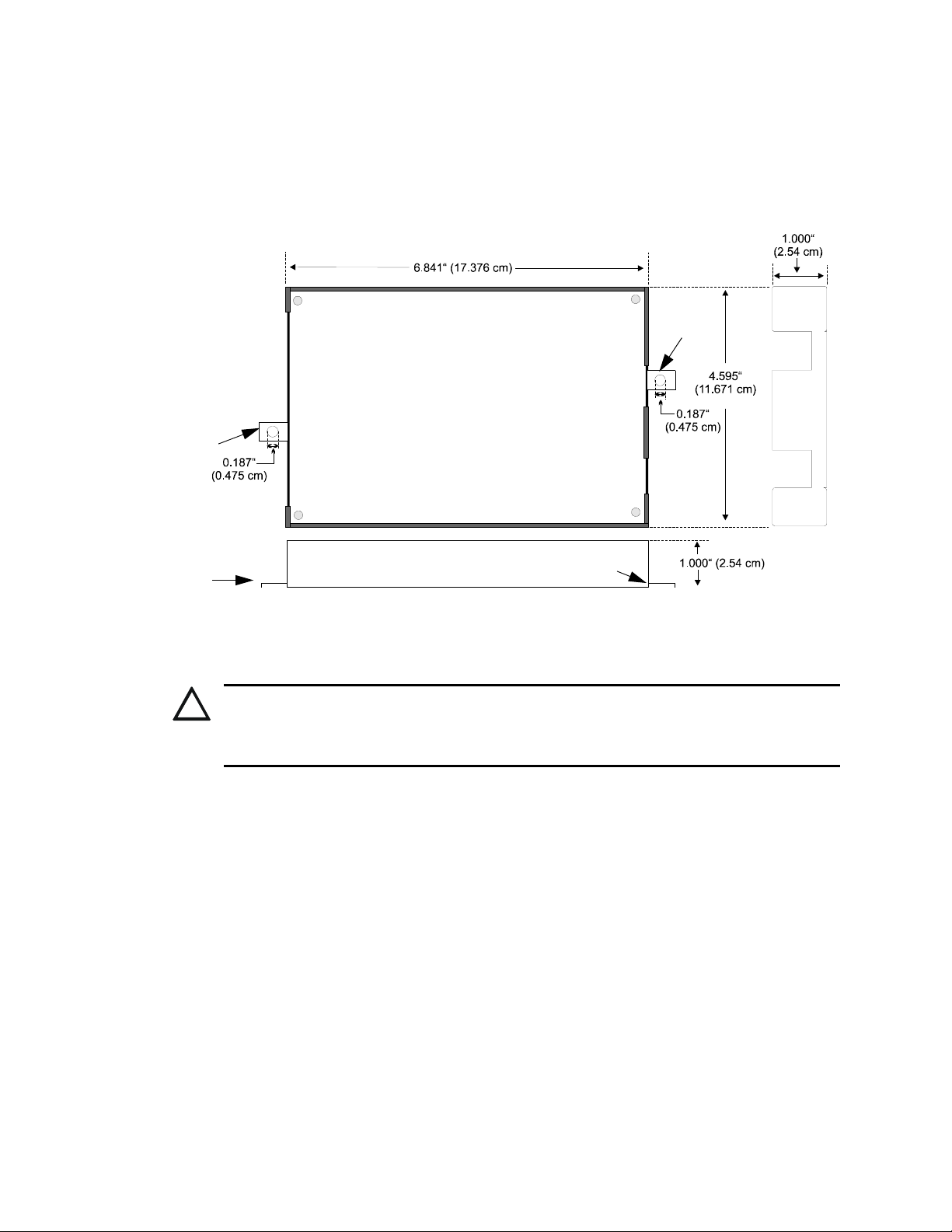
• 6.841" (17/376 cm) X 4.595" (11.671 cm) X 1.0" (2.54 cm) metal enclosure
• Communicates vital status of monitored control panel:
– fire alarm
– host control panel trouble
– fire supervisory
– AC (mains) power loss (programmable)
–other
• Communicates vital status of 411/411UD digital communicator:
– digital communicator troubles
– telephone Line 1 and 2 voltage fault
Figure 1.2 411UD Digital Communicator
411udbcvr.jpg 411bcvr.jpg
Figure 1.1 411 Digital Communicator

10 411 & 411UD Manual — P/N LS10105-000GE-E:A 1/29/2014
Product Description Specifications
– Primary Central Station number communication fault
– Secondary Central Station number communication fault
– system off-normal (local Program Mode entered)
– 24 Hour normal test
– 24 Hour abnormal test (24 hour test message with previously reported alarm or trouble still
active)
• Individual LEDs for:
– Communication Fail (visible with cover on)
– DACT Trouble (visible with cover on) - 411UD only
– Channel Active (visible with cover on) - 411UD only
– Primary Phone Line (PH1) active - 411UD only
– Secondary Phone Line (PH2) active - 411UD only
• Piezo sounder
• Local piezo silence switch which silences onboard piezo sounder (accessible without removing
cover)
• Real time clock
• Extensive transient protection
• One Form-C relay, fully programmable to activate for the following conditions:
– fire alarm
– host control panel trouble
– fire supervisory
– total communication failure
–ACloss
– DACT trouble (factory default for relay)
• PK-411 Remote Upload/Download Kit - 411UD only
• 'Dialer runaway' feature
• Trouble Resound - if a trouble is silenced and the cause of the trouble is not cleared, the panel
will resound the trouble buzzer every midnight, until the trouble is cleared
1.2 Specifications
Operating Power
The 411/411UD may be powered from UL listed control panels that output nonresettable and
power-limited 12 or 24 VDC power. The configuration of Jumper J4 determines whether 12 VDC
power is to be supplied directly to the 411/411UD circuit board or 24 VDC power is to be supplied
and then internally regulated down internally to 12 VDC.
DC Power - TB1 Terminals 4(+) and 5(-), Terminal 6 is Earth Ground
• J4 Jumper shorted on pins 2 and 3 - Filtered, nonresettable and power-limited 24 VDC
(nominal) power must be supplied at TB1 Terminals 4(+) and 5(-). UL-listed operating range
is 17 to 28 VDC. Current requirements are 64 mA in standby and 120 mA1while
communicating.
• J4 Jumper shorted on pins 1 and 2 - Filtered, nonresettable and power-limited 12 VDC
(nominal) power must be supplied at TB1 Terminals 4(+) and 5(-). UL-listed operating range
is 9.8 to 14 VDC. Current requirements are 88 mA in standby and 140 mA1while
communicating.
1. A maximum of 200 mA is possible with all input channels shorted, the 411/411UD communicating,
the Programmer connected, and Lamp Test active.

411 & 411UD Manual — P/N LS10105-000GE-E:A 1/29/2014 11
Circuits Product Description
Channels/Inputs1- TB2 Terminals 1 through 6 (411) or 8 (411UD)
Programmable Channels 1 through 3 (411) or 4 (411UD)
Power-limited circuitry
Operation: All channels NFPA Style B (Class B). Requires Normally Open contact to trigger
Normal Operating Voltage: 12 VDC
Alarm Current: 2.68 mA
End-Of-Line Resistor: 2.2K ohms, ½ watt (P/N 27070)
Short Circuit Current: 3.9 mA per channel/input
Restricted to 20 feet (6 m) in conduit and in the same room
One Form-C Relay - TB1 Terminals 1 through 3
Contact rating: 2.0 amps @ 30 VDC (resistive)
Non-supervised
1.3 Circuits
The 411/411UD circuit board utilizes surface mount technology and contains a MicroController
Unit (MCU), dual modular phone line jacks, piezo sounder, piezo silence switch, one programma-
ble relay and two connectors for input, output and power wiring.
1.3.1 Power Requirements
Voltage for the digital communicator may be a power-limited, filtered, nonresettable nominal 12
VDC (must be withing 9.8 to 14 VDC) or nominal 24 VDC (must be within 17 to 28 VDC).
Jumper J4 is used to select the power source. For 12VDC power, short pins 1 and 2. For 24 VDC,
short pins 2 and 3 as shown below.
1.3.2 Channels/Inputs
Three (411) or four (411UD) input channels are provided on the 411/411UD digital communicator
which are used for connection to the control panel being monitored. Each input can be pro-
grammed to monitor the control panel for:
• fire alarm activation
• trouble activation
• fire supervisory activation
• AC loss activation
Each input channel is configured as a Class B circuit and must be wired to a Normally Open con-
tact.
1. Channels/inputs do not support 2-wire smoke detectors.
3 2 1
3 2 1
J4- jumpered
pins 1 and 2
J4- jumpered
pins 2 and 3
12V operation
24V operation
Figure 1.3 J4 Jumper Selection
12 411 & 411UD Manual — P/N LS10105-000GE-E:A 1/29/2014
Product Description Controls and Indicators
1.3.3 Primary and Secondary Phone Lines
Modular jacks are used to interface the primary and secondary phone lines to the public telephone
network.
1.3.4 Earth Ground
Connect a separate earth ground wire to TB1 terminal 6 for transient protection.
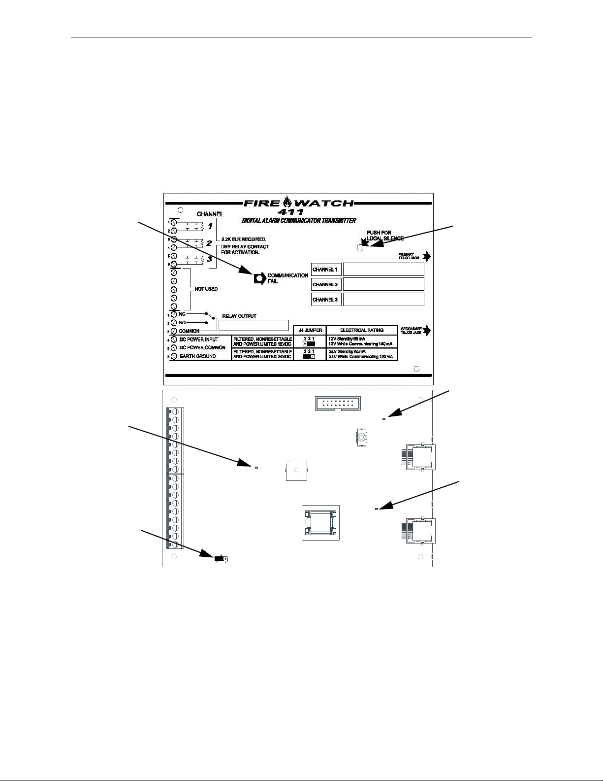
1.4 Controls and Indicators
Figure 1.4 411 Controls and Indicators
Comm.
Fail LED Piezo
Silence
Switch
Comm.
Fail LED
411Bbrd.wmf 411bcvr.jpg
J4 Jumper-
voltage select
PH1 LED
PH2 LED

411 & 411UD Manual — P/N LS10105-000GE-E:A 1/29/2014 13
Controls and Indicators Product Description
Front Panel Switch
Silence Switch - press to silence local 411/411UD piezo sounder
Piezo Sounder
The 411/411UD piezo sounder is used to locally annunciate DACT troubles. DACT troubles
include input channel open circuit, phone line 1 or 2 voltage fault, phone number 1 or 2 communi-
cation fault, total communication failure and communications disabled.
Front Panel Indicators
• Communication Fail - yellow LED
• DACT Trouble - yellow LED - 411UD only
• Channel Active - green LED - 411UD only
Circuit Board Indicators
• Primary Phone Line 1 (PH1) Active - red LED
• Secondary Phone Line 2 (PH2) Active - red LED
Figure 1.5 411UD Controls and Indicators
Channel
Active LED
DACT
Trouble
LED
Comm.
Fail LED Piezo
Silence
Switch
PH1 LED
PH2 LED
Comm.
Fail LED
DACT
Trouble
LED
Channel
Active LED
411udBbrd.wmf 411udbcvr.jpg
J4 Jumper-
voltage select

14 411 & 411UD Manual — P/N LS10105-000GE-E:A 1/29/2014
Product Description Digital Communicator Operation
1.5 Digital Communicator Operation
The 411/411UD has been designed to be compatible with a wide variety of fire alarm, non-fire and
combination control panels. Numerous formats are also available for communication to a central
station. Two modular phone jacks allow easy connection to telephone lines. Modular jacks are
labeled PH1 and PH2 for the Primary and Secondary phone lines. The digital communicator pro-
vides the following functions:
• Line Seizure- takes control of the phone lines, disconnecting any premises phones using the
same lines
• Off/On-Hook - perform on and off-hook status to phone lines
• Listen for dial tone - 440 hertz tone typical in most networks
• Dialing the Central Station(s) phone number - default is Touch-Tone®, programmable to
rotary
• Discern proper Central Station 'ACK' and 'Kiss-off' tone(s)
• Transmit data to the Central Station(s)
• Verify data has been accepted by the Central Station(s)
• Hang-up and release phone lines
• Communicate in a variety of formats (Table 4.1, “Format Selection Addresses (20 and 50)
Programming,” on page 42).
1.6 Telephone Requirements and Warnings
1.6.1 Telephone Circuitry - PH1 & PH2
AC Ringer Equivalence Number (REN) = 0.4B
Complies with FCC Part 68
Mates with RJ31X Male Connector
Supervision Threshold: less than 4.0 volts for 2 minutes
The REN is used to determine the quantity of devices which may be connected to the telephone
line. Excessive RENs on the telephone line may result in the devices not ringing in response to an
incoming call. In most, but not all areas, the sum of the RENs should not exceed five (5.0). To be
certain of the number of devices that may be connected to the line, as determined by the total
RENs, contact the telephone company to determine the maximum REN for the calling area.
1.6.2 Digital Communicator:
Before connecting the 411/411UD to the public switched telephone network, the installation of two
RJ31X jacks is necessary. The following information is provided if required by the local telephone
company:
Manufacturer: Fire•Lite Alarms Inc./Notifier
One Fire-Lite Place
Northford, CT 06472
Product Model Number: 411/411UD
FCC Registration Number: 1W6AL04B411UDAC
AC Ringer Equivalence 0.4B
FCC ID label is located on the inside cover.
Important! The DACT must not be used to dial a phone number that is call-forwarded per require-
ments of UL 864 9th Edition.

411 & 411UD Manual — P/N LS10105-000GE-E:A 1/29/2014 15
Operational Modes Product Description
1.6.3 Telephone Company Rights and Warnings:
The telephone company, under certain circumstances, may temporarily discontinue services and/or
make changes in its facilities, services, equipment or procedures which may affect the operation of
this digital communicator. However, the telephone company is required to give advance notice of
such changes or interruptions. If the digital communicator causes harm to the telephone network,
the telephone company reserves the right to temporarily discontinue service. Advance notification
will be provided except in cases when advance notice is not practical. In such cases, notification
will be provided as soon as possible. The opportunity will be given to correct any problems and to
file a complaint.
DO NOT CONNECT THIS PRODUCT TO COIN TELEPHONE, GROUND START OR PARTY
LINE SERVICES.
When the digital communicator activates, premise phones will be disconnected.
Two separate phone lines are required. Do not connect both telephone interfaces to the same tele-
phone line.
The digital communicator must be connected to the public switched telephone network upstream of
any private telephone system at the protected premises.
An FCC compliant telephone cord must be used with this equipment. This equipment is designed
to be connected to the telephone network or premises wiring using a compatible RJ31X male mod-
ular plug which is Part 68 compliant.
1.7 Operational Modes
1.7.1 Normal Mode
Normal Mode is the standard mode of operation in which the 411/411UD digital communicator
monitors the host control panel status as well as telephone line voltage and other internal circuits.
In addition to locally annunciating system trouble, active channel and communication fail, the digi-
tal communicator transmits system status information to UL listed central station receivers. Trans-
mitted data includes fire alarm, fire alarm trouble, supervisory alarm and AC loss information.
Specific digital communicator troubles are also transmitted.
1.7.2 Real Time Clock Mode
Real Time Clock Mode allows the user to change the digital communicator’s internal 24 hour
clock. Connecting an external Programmer allows access to the various Modes of operation.
While the communicator is in Real Time Clock Mode, it does not monitor channel inputs. Use of
this mode requires a valid password.
1.7.3 Program Mode
Program Mode is used to change the programmed functions of the 411/411UD digital communica-
tor. While the communicator is in Program Mode, it does not monitor channel inputs. Use of this
mode requires a valid password.
1.7.4 Troubleshoot Mode
Troubleshoot Mode may be used for testing the telephone line interconnect wiring. Connection
from the 411/411UD’s modular jacks, through the RJ31X jacks and into the telephone network may
be easily checked. In this mode, the Programmer keypad acts similar to a telephone touchpad.
While the communicator is in Troubleshoot Mode, it does not monitor channel inputs.
1.7.5 Default Mode
Default Mode may be used to return all 411/411UD programming back to the factory default set-
tings.
16 411 & 411UD Manual — P/N LS10105-000GE-E:A 1/29/2014
Section 2: Installation
2.1 Mounting Options
The 411/411UD may be mounted in any metal enclosure UL-listed for fire protective use. Mount-
ing tabs are provided for ease of mounting. No other devices are to be installed in the enclosure.
2.2 Operating Power
12VDC or 24VDC nominal power connections are made to TB1 on the 411/411UD circuit board.
When jumper J4 is shorted across pins 1 and 2, the 411/411UD is set for 12 VDC nominal operating
voltage. Power-limited, filtered, nonresettable 12 VDC nominal operating power can be supplied
directly to the 411/411UD by a UL listed 12 VDC power supply listed for fire protection or by a
nonresettable 12 VDC output from a control panel. Alternatively, shorting J4 Jumper on pins 2 and
3 allows the 411/411UD to be supplied by a power-limited, nonresettable, UL listed 24 VDC power
supply, which, in order to comply with UL 864 must be listed for Fire Protective Signaling Systems
or by a nonresettable 24 VDC output from a control panel. This nominal 24 VDC power is then
internally regulated by the digital communicator to 12 VDC operating power. Refer to Figure 1.3
on page 11 for more information on J4 and pin locations.
Note that upon power-up, the 411/411UD will immediately annunciate a DACT trouble since the
communicator is factory defaulted to 'communicator disabled' at program location 64.
!
CAUTION: DISCONNECT ALL SOURCES OF POWER
DISCONNECT ALL POWER BEFORE SERVICING THE 411/411UD. THE DIGITAL
COMMUNICATOR MAY BE DAMAGED BY REMOVING AND/OR INSERTING COMPONENTS OR
INTERCONNECTING CABLES WHILE THE UNIT IS ENERGIZED.
Figure 2.1 411/411UD Enclosure
Mounting bracket
Mounting
bracket
Mounting bracket
Mounting bracket
Bottom
411bkbox.wmf

411 & 411UD Manual — P/N LS10105-000GE-E:A 1/29/2014 17
Input Channels Installation
2.3 Input Channels
The 411/411UD digital communicator has three (411) or four (411UD) channel inputs. Each chan-
nel is a Style B (Class B) Initiating Device Circuit designed to accept any normally-open contact
device. Since channels do not latch, a reset switch is not provided by the 411/411UD. The commu-
nicator transmissions to a central station track the state of the inputs. Refer to Figure 2.2, “Style B
Channel Connections” on page 18 for information on wiring Style B circuits.
Each input channel monitors a normally open device and may be programmed as follows:
• fire alarm
• host control panel trouble
• fire supervisory
•ACLoss
Programming the input channel automatically programs the transmitted event code, however, the
event code can be changed since it is fully programmable. Event code transmissions can be tailored
to the specific application and requirements of the Central Station.
AC Loss Reporting - 411: Any channel programmed for AC Loss, will transmit a specific AC loss
signal only if the assigned Normally Open contact provides this function. Some panels provide an
option that will automatically delay the trigger of their system trouble relays upon loss of AC. If
this is provided by the host panel, program no additional delay in the 411. Be certain to verify the
method employed by the host panel to be monitored.
AC Loss Reporting - 411UD: Channel 4 which is defaulted to AC Loss on the 411UD, or any chan-
nel programmed for AC Loss, will transmit a specific AC loss signal only if the assigned Normally
Open contact provides this function. Some panels provide an option that will automatically delay
the trigger of their system trouble relays upon loss of AC. If this is provided by the host panel, use
Channel 2. Be certain to verify the method employed by the host panel to be monitored.
+ 24V -
NON-RST
POWER
+ 24V -
RST
POWER
REMOTE PWR
SUPPLY SYNC
+ -
1B+ 3B+ 3B- 1B- 2B+ 4B+ 4B- 2B- NO NC C NO NC C NC NO C
TB5
TB3 TB7
TB2 TB1 TB4 TB9
TB8TB6 TB10
3
2
JP4
1
2
3
JP6 J14
JP2
Xmt Rcv Dtr Gnd
A B
In+ In- Out+ Out-
+ -
A B
B+ A+ B- A- A B
Slc Slc Slc Slc Shield
411/411UD
24 VDC nonresettable power
+ -
Supervisory
Relay
Trouble
Relay
Alarm Relay
Channel 1
Channel 2
Channel 3
Channel 4
(411UD Only)
2.2K ELRs
P/N 27070
47K
ELR
SLC Loop
J4 shorted on
pins 2 and 3
Relay Output
(DACT Trouble)
Monitor Module
Circuit Input
Note: The monitor module input, which is being
used to monitor the 411/411UD Relay Output
(programmed for DACT Trouble), must be
programmed as 'DACT Trouble' at the FACP
2.2K
ELR
9200c411u.wmf
Figure 2.1 Typical FACP Connection to 411/411UD
Addressable FACP
18 411 & 411UD Manual — P/N LS10105-000GE-E:A 1/29/2014
Installation Output Circuits
The factory default programming for each channel is as follows:
• Channel 1 - fire alarm
• Channel 2 - host control panel trouble
• Channel 3 - fire supervisory
• Channel 4 (411UD Only) - AC Loss
Channel Labels
Note that space is provided for labeling the function of each channel. Write the function that has
been programmed for each channel in the white boxes located to the right of the channel designator.
2.4 Output Circuits
Relays
The 411/411UD provides one Form-C relay rated for 2.0 amps @ 30 VDC (resistive). The relay is
programmable for activation on fire alarm, host panel trouble, fire supervisory, total communica-
tion failure, AC loss and DACT trouble.
Relay Label
Note that space is provided for labeling the function of the relay. Write the function that has been
programmed for the relay in the white box located below the relay designator.
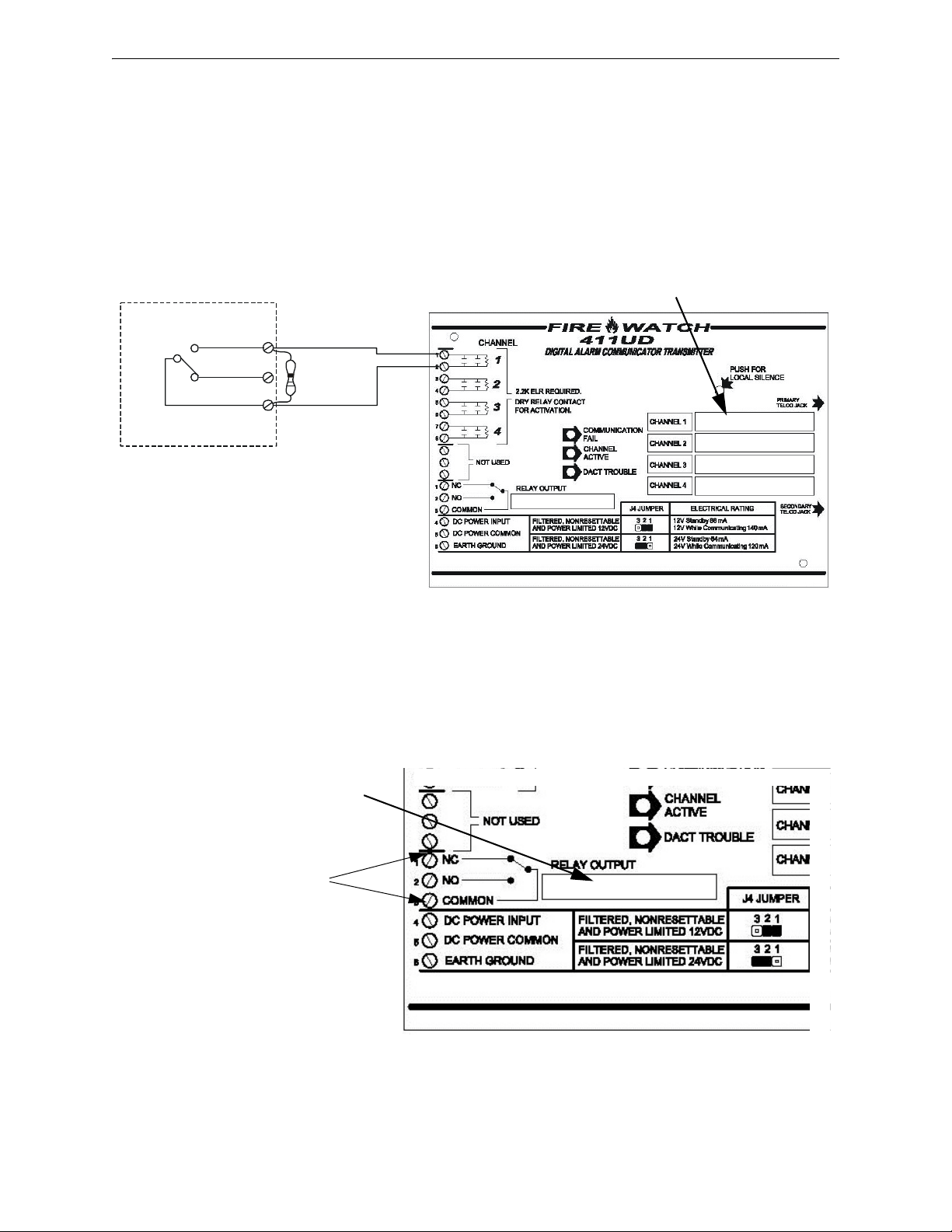
Figure 2.2 Style B Channel Connections
Normally Open Contact Device
2.2K ELR
P/N 27070
Channel/Input Labels
411udbchl.wmf
Inputs are
power-limited
Figure 2.3 Programmable Relay
Relay Label
One Form-C Relay
(nonsupervised)
411udbcvr.jpg

411 & 411UD Manual — P/N LS10105-000GE-E:A 1/29/2014 19
Telephone Circuits Installation
2.5 Telephone Circuits
Provision to connect two independent telephone lines is available via two telephone jacks labeled
PH1 (Primary) and PH2 (Secondary). Telephone line control/command is possible via double line
seizure as well as usage of an RJ31X style interconnection. (RJ31X jacks must be ordered sepa-
rately).
CAUTION: It is critical that the 411/411UD be located as the first device on the incoming tele-
phone circuit to properly function.
Figure 2.4 Wiring Phone Jacks
To Premises Phone
Green Wire
Red Wire
Red Wire
Tip
Ring
Ring
Tip
Ring
Tip
Ring
Tip
To Premises
Phone
(Primary Lines) Incoming
Telco Phone Lines
(Secondary Lines) Incoming
Telco Phone Lines
Note: Shorting bars
inside RJ31X Jack
removed during male
plug insertion
7 foot Cable (MCBL-7)
Not supplied - Order
Separately
Modular
Female
Connector
Secondary Phone Line
PH2
Male Plug Connectors
Primary Phone Line
PH1
411/411UD
Green Wire
411bjack.wmf
RJ31X
JACK
RJ31X
JACK
20 411 & 411UD Manual — P/N LS10105-000GE-E:A 1/29/2014
Installation Optional Programmer
2.6 Optional Programmer
The optional Fire-Watch 411 Series DACT Programmer (Model PRO-411) is used to:
• switch between the digital communicator's five Modes of operation
• set the digital communicator's 24 hour internal clock in Real-Time Clock Mode
• program the 411/411UD digital communicator in Program Mode
• test the telephone lines interconnect in Troubleshoot Mode
• return all digital communicator programming to the factory default settings in Default Mode
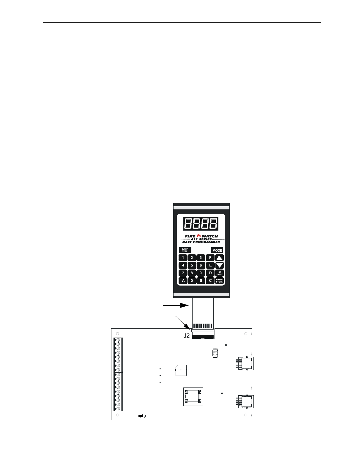
To use the PRO-411 Programmer:
1. Remove all power from the 411/411UD.
2. Remove the two screws holding the 411/411UD cover in place and remove the cover.
3. Connect the Programmer cable to connector J2 located in the upper right corner of the
411/411UD. Note that the key on the connector must align with the slot in the J2 connector.
4. Reapply power to the 411/411UD.
5. Operate the Programmer by pressing the MODE key. Enter the appropriate four digit code
and then press the [ENTER/STORE] key.
Note that it is not possible to switch from Normal Mode to any other mode if any of the 3 (411) or
4 (411UD) Channels is programmed for fire alarm or fire supervisory, and is active, that is, in alarm
(shorted).
Cable attached to Programmer
411/411UD
Programmer
J2 connector
411udbpro.wmf
Figure 2.5 Programmer Connection to 411/411UD
Other manuals for FireWatch 411UD
1
This manual suits for next models
1
Table of contents
Other Fire-Lite Security System manuals

Fire-Lite
Fire-Lite BG-12LAO User manual

Fire-Lite
Fire-Lite BG-12 Series User manual

Fire-Lite
Fire-Lite Fire-Lite Alarms BB-26 User manual

Fire-Lite
Fire-Lite BG-12LR User manual

Fire-Lite
Fire-Lite FireWatch 411UD User manual

Fire-Lite
Fire-Lite Device User manual

Fire-Lite
Fire-Lite FIRE-LITE 411UDAC Operating instructions

Fire-Lite
Fire-Lite DACT-UD User manual

Fire-Lite
Fire-Lite Fire-Lite Alarms BB-17F Technical manual

Fire-Lite
Fire-Lite MBT-1 User manual


