BG-12LR and BG-12LRA
Agent Release Pull Stations
Document 51370 Revision A ECN 00-190 06/16/2000
Door Reattachment
If the door becomes detached, complete the following steps to
reattach the door to the backplate. The door cannot be connected
to the pull station if the unit is mounted to a backbox.
1. Position the door and backplate side by side in the full open
position (i.e. 180-degrees with respect to each other .
2. With the backplate position fixed, move the door behind
the backplate, as shown in the illustration, part A.
3. Align the hinge posts and holes by bringing the door up to
meet the backplate, paying particular attention to the
keying that occurs when the doors post hole is aligned to
the backplates hinge post. Refer to the illustration, part B.
4. With the two pieces aligned and keyed together, slide the
holes down onto the posts. Refer to the illustration, part C.
5. Holding the backplate, close the door slightly to lock the
door and backplate together.
BG12LRf ce.cdr
S itch Contact Rating
Switch contacts are rated for 0.25 A at 30 volts (AC or DC .
Description
The BG-12LR and BG-12LRA Agent Release Pull Stations are
designed for use with FireLite control panels that include agent
release capabilities, such as the Sensiscan 2000 and MRP-4424.
These stations are ideally suited for areas such as clean rooms
and computer rooms, where a chemical agent is used to
extinguish a fire. Both pull stations provide a dual-action,
normally open contact, release initiating point. The BG-12LRA
also includes a manual abort switch, System Normal LED, and
System Activated (release LED. The dual-action stations
require pushing the handle, then pulling the handle down for
activation. Like the entire BG-12 Series of manual fire alarm
stations, the releasing stations are UL listed and meet the ADA
requirement of a 5-lb. Maximum pull force to activate. Operating
instructions are molded into the handle.
Agent Releasing Models Available
BG-12LR. Dual action with screw terminal connections and
key lock/reset. Front of station (door is identified with the words
"AGENT RELEASE" and a symbol illustrating discharge. This
model can be semi-flush-mounted to a standard single-gang
electrical box or surface-mounted to a SB-10 backbox.
BG-12LRA. All features as BG-12LR plus manual abort switch,
System Normal (power-on LED, and System Activated (release
LED. This model must be surface-mounted to an SBA-10
backbox.
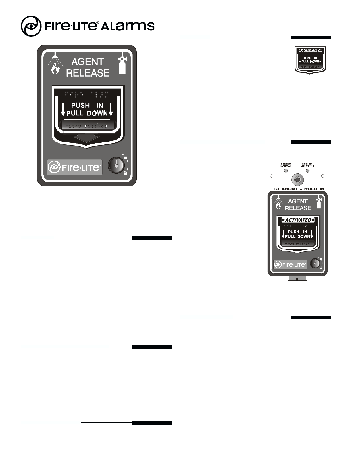
Dual Action BG-12LR
Operation
To initiate an agent release, push in the pull
station handle then pull it down. The word
"ACTIVATED" appears after the handle is
pulled down. The agent release pull station
remains in the activated position until reset.
To reset the BG-12LR or BG-12LRA:
1 Unlock and open the station door. Once open, the handle
will return to the "NORMAL" position.
2 Close and lock the door. Closing the door automatically
resets the alarm switch to the "NORMAL" position.
Note: Opening the door will not activate or deactivate the alarm
switch.
BG12LRA ctiv ted.cdr
Dual Action BG-12LRA
(Shown activated)
cth ndle.cdr
Abort Feature (BG-12LRA only)
The operation and reset of the
BG-12LRA agent release pull
station is the same as the BG-
12LR, with the addition of the
Abort Feature:
The System Normal LED will stay
illuminated when the Agent
Release Control Panel is "All
Systems Normal." When the
station has been activated,
initiating the agent release process
in the control panel, the System
Activated LED will illuminate. If
the control panel has been
configured to abort the releasing
of an extinguishing agent, then
pushing and holding-in the abort
switch will cancel the agent release
sequence. Please refer to the
respective agent release control
panel manual for further
instructions about using the Abort
feature.


