FireClass FC410LP Series User manual

DEUTSCH
FC410LP SIRENENMODUL UND SIRENENMODUL MIT BLINKLICHT
Best.-Nr. 516.800.760 (Sirenenmodul FC410LPSYR für Innenbereiche, rot)
Best.-Nr. 516.800.761 (Sirenenmodul FC410LPSYW für Innenbereiche, weiß)
Best.-Nr. 516.800.762 (Sirenenmodul FC410LPSY für Außenbereiche, IP 65, rot)
Best.-Nr. 516.800.763 (Sirenenmodul mit Blinklicht FC410LPAVR für Innenbereiche, rot)
Best.-Nr. 516.800.764 (Sirenenmodul mit Blinklicht FC410LPAVW für Innenbereiche, weiß)
Best.-Nr. 516.800.766 (Sirenenmodul mit Blinklicht FC410LPAV für Außenbereiche, IP 65, rot)
ANWENDUNG
Die Sirenenmodule mit und ohne Blinklicht sind zum Einsatz in den adres-
sierbaren FC-Brandmeldesystemen bestimmt. Die Sirene hat zwei La-
utstärkeeinstellungen, das Blinklicht zwei Blinkfrequenzen (siehe Abschnitt
„Schall- und Lichtleistungsdaten“ ). Die Module sind miteinander synchroni-
siert, jedoch nicht mit den FC-Meldersockeln mit Sirene (FC430SB) und an-
deren Elementen (FC410SNM und FC430SAB). Das erste Aufleuchten des
Blinklichts wird mit der Sirenenauslösung synchronisiert. Die Module
verfügen über einen eingebauten Isolator.
TECHNISCHE DATEN
Elementtyp (Kennung)
Systemkompatibilität: Adressierbares FC
Brandmeldesystem
Elementtyp (Kennung)
Sirenenmodul FC410LPSY-R/W innen: 183
Sirenenmodul FC410LPSY außen: 183
Sirenenmodul mit Blinklicht FC410LPAV-R/W innen: 184
Sirenenmodul mit Blinklicht FC410LPAV außen: 184
Mechanische Daten
Material
Außenbereiche: ABS FR
Innenbereiche: ABS/PC FR
Farbe
weiß: 21-0302
rot: 21-0301
Abmessungen: siehe Abbildung 6
Gewicht
Sirenenmodul innen/außen: 228 g / 310 g
Sirenenmodul mit Blinklicht innen/außen: 218 g / 300 g
Elektrische Daten
Spannungsversorgung aus der Ringleitung: 20 bis 40 V
Stromaufnahme (Ringleitung)
Im Ruhezustand: 0,45 mA
Im Alarmzustand (Sirenenmodul)
niedrige Lautstärke: 3,4 mA
hohe Lautstärke: 8,5 mA
Im Alarmzustand (Sirenenmodul mit Blinklicht)
langsames Blinken und niedrige Lautstärke: 6,5 mA
schnelles Blinken und niedrige Lautstärke: 7,6 mA
langsames Blinken und hohe Lautstärke: 11,1 mA
schnelles Blinken und hohe Lautstärke: 13 mA
Technische Daten des eingebauten Isolators
max. Linienspannung (Vmax): 40 V
min. Linienspannung in Ruhe (Vmin): 19 V
max. Dauerstrom in durchgeschaltetem
Zustand (I Cmax
): 2A
max. Schaltstrom bei Kurzschluss (I Smax
): 2A
max. Leckstrom (I Lmax
) bei isoliertem
Kurzschluss: 6 mA in Meldergruppe (10 mA
in den Isolator)
max. Serienwiderstand in leitendem Zustand: 0,25 Ohm
Auslösekriterium (Öffnen)
Linienspannung: < 19 V
Durchschaltkriterium (Schließen)
Linienspannung: 3,3 V
Umgebungsbedingungen
Betriebstemperatur
Innenbereiche: -10 bis +55 °C
Außenbereiche: -20 bis +70 °C
Lagertemperatur
Innenbereiche: -25 bis +70 °C
Außenbereiche: -25 bis +70 °C
Luftfeuchtigkeit ohne Betauung (max.): 95 %
Schutzart
Außenbereiche: IP 21C (EN 60529)
Innenbereiche:IP 65 (EN 54-3 zugelassen für
IP 33C)
Schall- und Lichtleistungsdaten
Schallleistung
Schalldruckpegel in 1 m (hohe Lautstärke): 103 dB±3
Schaldruckpegel in 1 m (niedrige Lautstärke): 90 dB±3
Lichtleistung
Blinkleistung/Lichtausbeute (min.): 2 Cd, Raumverteilung 60° bei
1,5 Cd
Blinkfrequenz
schnelles Blinken: 1 Hz
langsames Blinken: 0,5 Hz
Synchronisierung (max.): 30 ms innerhalb 30 min
IDENTIFIZIERUNG DER TEILE
Siehe Abbildungen FIG 1, 2, 3, 5 und 6.
1Programmieranschluss 6Sirenenmodul (mit Blinklicht)
innen
2FC-Zentrale 7Sirenenmodul (mit Blinklicht)
außen
3801HL Hinweisleuchte 8Bohr-Markierungen für die
stufennippel
4Sirenenmodul innen
9
Bohr-Markierungen für die
stufennippel (ober- und
unterseite)
5Sirenenmodul außen
EINBAU
Das Sirenenmodul kann auf eine Unterputzdose mit dem Befestigungsabstand
60 mm oder direkt auf eine entsprechende Montagefläche montiert werden.
Das Rückgehäuse des Sirenenmoduls für Innenbereiche verfügt über 2
Bohr-Markierungen (Schlitze) für die Kabeleinführung auf der Oberseite.
Auf dem Rückgehäuse des Sirenenmoduls für Außenbereiche sind 3
Bohr-Markierungen (Bohrungen) auf der Ober-und Unterseite vorgefertigt
(siehe Abbildung 6).
Das Sirenenmodul mit und ohne Blinklicht für Innenbereiche rastet im
Gehäuse ein und kann nur mit dem beiliegenden Schlüssel entfernt werden.
Montagehinweise Dok.-Version 2.0 1
FireClass FC410LP Sirenenmodul und Sirenenmodul mit Blinklicht

Das Sirenenmodul mit und ohne Blinklicht für Außenbereiche ist mit 4
Inbusschrauben am Gehäuse befestigt.
TON- UND LICHTEINSTELLUNGEN
Über Programmier software können folgende Charakteristiken eingestellt
werden:
ØTontyp (16 Töne)
ØLautstärke
ØBlinkfrequenz
+Toneinstellung
Die Tontyp-Einstellung muss bei allen an eine FC-Zentrale angeschlos-
senen Sirenenmodulen gleich sein.
ADRESSEINSTELLUNG
Im Auslieferungszustand ist die Adresse standardmäßig auf 255 gesetzt.
Um die individuelle Systemadresse einzustellen, schließen Sie das
Sirenenmodul an den Programmieranschluss an (siehe Abbildung 3).
VERKABELUNG
An die Anschlussklemmen können Kabel mit folgenden Drahtquerschnitten
angeschlossen werden:
ØLitzendraht: 0,14 mm2bis 1,0 mm2
ØFester Draht: 0,14 mm2bis 1,5 mm2
Es werden geschirmte Brandmeldekabel des Typs J-Y(St)Y nx2x0,8
empfohlen.
ANSCHLUSS
1) Die Verkabelung muss entsprechend DIN und VdS erfolgen.
2) Alle Leiter müssen erdfrei sein.
3) Stellen Sie die korrekte Polarität der Verkabelung sicher, bevor Sie das
Sirenenmodul an die Ringleitungsspannung anschließen.
4) Schließen Sie das Sirenenmodul an (siehe Abb. 5).
2 Montagehinweise Dok.-Version 2.0
FC410LP Sirenenmodul und Sirenenmodul mit Blinklicht FireClass

ENGLISH
FC410LP SERIES OF LOOP POWERED SOUNDERS AND SOUNDER-BEACONS
INTRODUCTION
The FC410LP Series of Loop Powered Addressable Sounder/ Sounder-Bea-
cons are designed to be driven from an FireClass control panel via the ad-
dressable loop. The FC410LP Series of sounders/sounder beacons consist:
FC410LPSYR Sounder (indoor use) - red housing
FC410LPSYW Sounder (indoor use) - white housing
FC410LPSY Sounder IP65 (outdoor use) - red housing
FC410LPAVR Sounder-Beacon (indoor use) - red housing
FC410LPAVW Sounder-Beacon (indoor use) - white housing
FC410LPAV Sounder-Beacon IP65 (outdoor use) - red housing
The sounder has two volume settings ‘High’ (103 dB ±3) or ‘Low’ (90 dB ±3).
The beacon has two flash rates ‘Slow Flash’ (1/2 Hz) or ‘Fast Flash’ (1 Hz).
The FC410LP devices are synchronised, but not synchronous with other
FireClass sounders (FC430SB/FC410SNM) and beacons (FC430SAB).
The first flash of the beacon is synchronised with the start of the tone.
The FC410LP devices have a built in two port isolator.
TECHNICAL SPECIFICATION
Mechanical Characteristics
Dimensions: See Fig.
Weight:
Sounder Indoor: 228 g
Sounder Outdoor: 310 g
Sounder-Beacon Indoor: 218 g
Sounder-Beacon Outdoor: 300 g
Materials
Indoor: ABS FR
Outdoor: ABS/PC FR
Colour: White 21-0302
Red 21-0301
Mounting Requirements: 50 mm or 60 mm Besa box or surface mount.
The indoor back box has to two drill positions (on the bottom) for gland holes.
The outdoor back box has 3 drill positions (top and bottom) for gland holes.
The indoor sounder/indoor sounder beacon body clips onto the backbox and
can only be removed by the use of a special key.
The outdoor sounder /outdoor sounder beacon is secured to the backbox by
four allan key screws.
Environmental Characteristics
Temperature: Indoor Outdoor
Operating: -10°C to +55°C -20°C to +70°C
Storage: -25°C to +70°C -25°C to +70°C
Humidity: Up to 95% RH (non-condensing)
Pressure: Sounder output is quoted for atmospheric pressure
of 1000mBar.
Vibration: Meets the requirements of EN 54-3.
Corrosion: passes the SO2corrosion test from EN 54-3.
EMC: The FC410LP devices comply with the following:
Product family standard EN50130-4 in respect of
Conducted Disturbances, Radiated Immunity, Elec-
trostatic Discharge, Fast Transients and Slow High
Energy.
EN61000-6-3 for Emissions.
IP Rating: Indoor Outdoor
IP21C (EN 60529) IP65 (EN54-3 approved to IP33C)
Sound Performance: high volume low volume
SPL @ 1m: 103 dB ±3 90 dB ±3
Sound Dispersion
Horizontal: >90% over 90° (±45° from axis)
Pole Mounted: >80% over 360° (from axis)
Light Performance:
Flash Power/Light
Output: 2 candela minimum on axis, spacial distribution 60°
@ 1.5 cd
Flash Rate /s: Fast Flash 1Hz or
Slow Flash 1/2Hz
Synchronisation: 30ms in 30 minutes maximum
Electrical Characteristics
Addressable Loop Voltage: 20-40Vdc
DC Loop Loading
Quiescent: 450 µA
Alarm:
Sounder: Low Volume 3.4 mA
Sounder: High Volume 8.5 mA
Sounder + Beacon: Slow Flash + Low Volume 6.5 mA
Sounder + Beacon: Fast Flash + Low Volume 7.6 mA
Sounder + Beacon: Slow Flash + High Volume 11.1 mA
Sounder + Beacon: Fast Flash + High Volume 13 mA
Isolator
Maximum Loop Voltage: 40 Vdc
Minimum Loop Voltage: 19 Vdc
Maximum Rated Continuous Current (Isolator Closed): 2 A
Maximum Rated Switching Current (s/c): 2 A
Maximum Leakage Current (Isolator Open): 6 mA into zone
(10 mA into Isolator)
Maximum Series Impedance (Isolator Closed): 0.25 W
Isolator SwitchingThreshold (Isolator Closed to Open): 19V or below
Isolator Switching Threshold (Isolator Open to Closed): 3.3V from s/c
Sounder Tones
Table 1 details the tones available for selection in FireClass Console (Future
use expandable to 32 tones).
Approved Tones
The following tones are approved by LPCB to the specifications as shown in
Table 2.
Identification of parts
See Figs 1, 2, 3, 4, 5 and 6.
1Programming Port 6Indoor Sounder/Beacon
2FireClass Control Panel 7Outdoor Sounder/Beacon
3801HL Remote Indicator 8Drill position for glands
4Indoor Sounder 9Drill positions for glands top
and bottom
5Outdoor Sounder
Address Programming
The FC410LP devices have a default factory set address of 255, this must
be set to the loop address of the device using the FC490ST Service Tool.
The sounder is programmed with the address prior to being installed by us-
ing the internal programming port (see Fig. 3).
+This device use one address only on the loop.
Fixing instructions Doc. version 2.0 16 March 2012 3
FireClass FC410LP Series of Loop Powered Sounders and Sounder-Beacons
FC410LP Configuration
Sounder tone (Device Mode), sounder volume output (Sensitivity) and bea-
con flash rate (Device Mode) are configured in FireClass Console.
Fault Monitoring
Both the sounder and beacon are monitored.For further details on the appli-
cation of this function, refer to the Technical Publications of the relevant
Control and Indicating equipment.
Isolator Operation
The built-in isolator serves as a protection deviceagainst short circuits. It op-
erates by isolating the section of line containing the short circuit from de-
vices on the line and from the rest of the line (refer to Fig. 4). Optimum
operation requires the line to be wired as a loop, so that a section of line with
a short circuit can be isolated between a pair of isolator devices (including
FC410LP devices).
In order to enable the isolator’s use in a looped circuit, it is capable of pass-
ing current in both directions (Loop IN to Loop OUT or Loop OUT to Loop
IN). In the event of a line short circuit, the line isolator continues to power its
associated FC410LP Sounder or Sounder-Beacon, providing that either
Loop IN or Loop OUT remains intact. When a short circuit develops, the ad-
jacent isolator devices will isolate both sides of the loop from the faulty de-
vice/cable.
The operation of the FireClass Loop driver means that there are effectively 2
operational modes for the built-in isolator.
1) When the loop is first powered, if a section of the line appears as a low
impedance (with an equivalent resistance of <400W), the isolator will re-
strict the power to that section of line until the fault is cleared.
2) If a short circuit is introduced onto the line when the loop is already pow-
ered up, in most instances the controller’s internal protection will switch
in before the line isolator. The voltage is then removed from the line by
the controller, on restoration, the isolator devices will isolate the low im-
pedance section of the line.
CABLING
Cables are to be selected in accordance with the system design document
and the requirements of the applicable standards. Cabling should be con-
nected as shown in Fig. 5, ensuring correct polarity.
Each terminal connection will accept wire size up to 2.5mm2.
+The section is calculated based on the characteristics of the cable and
the load.
+Suitable glands must be used with the outdoor device to keep the IP65
rating.
ORDERING INFORMATION
FC410LPSYR Sounder (indoor use) – red housing
FC410LPSYW Sounder (indoor use) – white housing
FC410LPSY Sounder IP65 (outdoor use) – red housing
FC410LPAVR Sounder-Beacon (indoor use) – red housing
FC410LPAVW Sounder-Beacon (indoor use) – white housing
FC410LPAV Sounder-Beacon IP65 (outdoor) – red housing
RECYCLING INFORMATION
Customers are recommended to dispose of their used equipments (panels,
detectors, sirens, and other devices) in an environmentally sound manner.
Potential methods include reuse of parts or whole products and recycling of
products, components, and/or materials.
WASTE ELECTRICAL AND ELECTRONIC EQUIPMENT (WEEE) DIRECTIVE
In the European Union, this label indicates that this product
should NOT be disposed of with household waste. It should be
deposited at an appropriate facility to enable recovery and re-
cycling.
The manufacturer reserves the right to change the technical specifications
of this product without prior notice.
4 Fixing instructions Doc. version 2.0 16 March 2012
FC410LP Series of Loop Powered Sounders and Sounder-Beacons FireClass
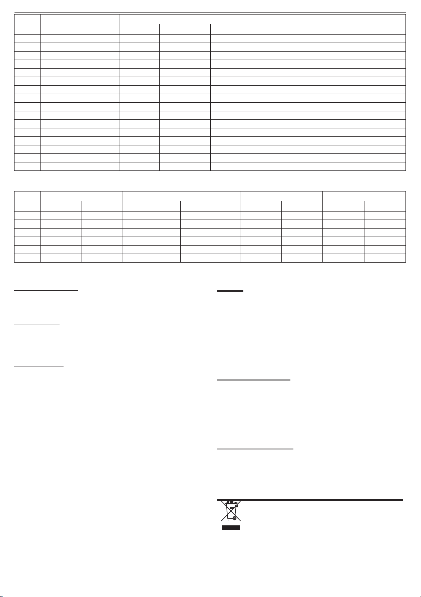
Device Name Tone Description
Mode Pattern Frequency (Hz) Rate
1 Duct Slow Whoop Sweep 500 to 1200 500 Hz rising to 1200 Hz over 3.5 s silence 0.5 s repeat
2 Sweep velocea7Hz Sweep 800 to 970 0.1428 s ramp 7 Hz
3 BS 1 Hz Sweep Sweep 800 to 970 1 Hz
4 2 Tone Alternating 660/880 500 ms per tone
5 Temporal 4 Intermittent 880 500 ms on 500 ms off x 4 followed by 1.5 s silence
6 Temporal 3 Intermittent 880 500 ms on 500 ms off x 3 followed by 1.5 s silence
7 March Time Beep Intermittent 880 500 ms on 500 ms off
8 Continuous 970 Continuous 970 Steady
9 Continuous 850 Continuous 850 Steady
10 DIN 1 Hz Sweep Sweep 1200 to 500 1200 Hz falling to 500 Hz over 1 s and repeat
11 Banshee LF Buzzer Sweep 800 to 950 120 Hz
12 3 Hz Banshee Fast Sweep Sweep 800 to 950 3 Hz
13 9 Hz Banshee Fast Sweep Sweep 800 to 950 9 Hz
14 Alternating Alternating 554/440 554 Hz for 100 ms and 440 Hz for 400 ms
15 Yodalarm Alternating 800/1000 250 ms for each frequency
16 Conventional Bell Continuous 1450 Steady
Tab. 1 Sounder Tones.
Continuous 850 Hz Duct Slow Whoop 500 Hz to 1200 Hz 7 Hz Fast Sweep Temporal 3 880 Hz
Angle 40 V 20 V 40 V 20 V 40 V 20 V 40 V 20 V
15° 84.0 83.0 85.4 84.4 84.2 83.4 81.2 79.7
45° 93.9 92.5 95.2 94.2 94.3 93.7 92.8 91.0
75° 96.3 95.1 97.7 96.3 97.3 96.0 95.0 94.3
105° 62.2 94.8 97.0 95.8 96.7 95.5 94.4 93.6
135° 93.1 92.1 94.0 93.3 93.9 93.2 92.0 90.9
165° 82.0 81.8 84.9 84.1 84.6 83.8 81.2 80.9
Tab. 2 Operational Performance – Maximum Volume dB(A).

ITALIANO
SIRENE CON E SENZA LAMPEGGIATORE ALIMENTATE DA LOOP SERIE FC410LP
INTRODUZIONE
La serie FC410LP di Sirene/Sirene con Lampeggiatore Indirizzabile Alimen-
tate da Loop sono progettate per essere pilotate da una centrale FireClass
attraverso il Loop indirizzabile. La serie FC410LP di Sirene/Sirene con
Lampeggiatore è composta da:
FC410LPSYR Sirena (uso interno) – rossa
FC410LPSYW Sirena (uso Interno) – bianca
FC410LPSY Sirena IP65 (uso esterno) – rossa
FC410LPAVR Sirena con Lampeggiatore (uso interno) – rossa
FC410LPAVW Sirena con Lampeggiatore (uso interno) – bianca
FC410LPAV Sirena con Lampeggiatore IP65 (uso esterno) – rossa
La sirena ha due impostazioni per il livello del volume: ‘Alto’ (103dB ±3) o
‘Basso’ (90dB ±3).
Il lampeggiatore ha due velocità di lampeggio: ‘Lampeggio Lento’ (1/2 Hz) o
‘Lampeggio veloce’ (1 Hz).
I dispositivi FC410LP sono sincronizzati, ma non lo sono con le altre sirene
(FC430SB/FC410SNM) e lampeggiatori (FC430SAB) FireClass.
Il primo lampeggio del Lampeggiatore è sincronizzato con l’inizio del tono.
I dispositivi della serie FC410LP hanno un isolatore a due porte integrato.
CARATTERISTICHE TECNICHE
Caratteristiche meccaniche
Dimensioni: vedere Fig.
Peso
Sirena Interna: 228 g
Sirena Esterna: 310 g
Sirena con Lampeggiatore Interna: 218 g
Sirena con Lampeggiatore Esterna: 300 g
Materiali
Sirene da Interno: ABS FR
Sirene da Esterno: ABS/PC FR
Colore: bianco 21-0302
rosso 21-0301
Requisiti di montaggio: scatolaBesada50o60mm,oavista.
Il fondo da interno ha due fori (nella parte inferiore) per passacavi. Il fondo
da esterno ha tre fori (nella parte inferiore e superiore) per passacavi.
Il corpo delle Sirene e delle Sirene con Lampeggiatore da interno, si
aggancia al fondo e può essere rimosso solo con l'uso di una chiave
speciale. Il corpo delle Sirene e delle Sirene con Lampeggiatore da esterno,
si fissa al fondo con 4 viti a brugola.
Caratteristiche Ambientali
Temperatura: Sirene da Interno Sirene da Esterno
di Funzionamento: -10°C ÷ +55°C -20°C ÷ +70°C
di Stoccaggio: -25°C ÷ +70°C -25°C ÷ +70°C
Umidità: fino a 95% UR (senza condensa)
Pressione: la pressione sonora è misurata per una pressione
atmosferica di 1000 mBar.
Vibrazione: conforme ai requisiti della EN 54-3.
Corrosione: supera il test di corrosione SO2della EN 54-3.
Compatibilità
Elettromagnetica: i dispositivi della serie FC410LP sono conformi alle
seguenti norme:
famiglia di prodotto standard EN50130-4 rispetto
alle Perturbazioni Dirette, Immunità Irradiata,
Scarica Elettrostatica, Transitorie Rapide e Alta
Energia Lenta.
EN 61000-6-3 per le Emissioni.
Grado IP: Sirene da Interno Sirene da Esterno
IP21C (EN 60529) IP65 (IP33CperlaEN54-3:2007)
Prestazioni Sonore: volume alto volume basso
SPL @ 1m: 103 dB ±3 90 dB ±3
Dispersione Sonora
Orizzontale: >90% su 90° (±45° dall'asse)
Montato a Palo: >80% su 360° (dall'asse)
Caratteristiche
Lampeggio:
Potenza Lampeggio/Intensità in Uscita: sull'asse minimo 2 candela,
distribuzione spaziale 60°@ 1.5cd
Velocità Lampeggio: lampeggio veloce 1Hz o
lampeggio lento 1/2Hz
Sincronizzazione: massimo 30ms in 30 minuti
Caratteristiche elettriche
Voltaggio Loop Indirizzabile: 20-40Vcc
Carico sul Loop (DC)
A riposo: 450µA
Allarme:
Sirena: Basso Volume 3,4mA
Sirena: Alto Volume 8,5mA
Sirena + Lampeggiatore: lampeggio Lento + Basso Volume 6,5mA
Sirena + Lampeggiatore: lampeggio Veloce + Basso Volume 7,6mA
Sirena + Lampeggiatore: lampeggio Lento + Alto Volume 11,1mA
Sirena + Lampeggiatore: lampeggio Veloce + Alto Volume 13mA
Isolatore
Massimo Voltaggio sul Loop: 40 Vcc
Minimo Voltaggio sul Loop: 19 Vcc
Massima Corrente Continua
Nominale (Isolatore Chiuso): 2A
Massima Corrente
Commutata Nominale (s/c): 2A
Massima Corrente di
dispersione (Isolatore Aperto): 6mA nella zona
(10mA nell' isolatore)
Massima Impedenza di serie
(Isolatore Chiuso): 0,25W
Soglia di commutazione isolatore
(TransizionedaChiusoadAperto): 19V o sotto
Soglia di commutazione isolatore
(Transizione da Aperto a Chiuso): 3,3V da s/c
Suoni Sirene
La tabella 1 mostra i toni disponibili, selezionabili nel Programma Software.
(Espandibile a 32 toni, uso futuro).
Suoni Approvati
Nella tabella 2 sono mostrate le specifiche dei toni approvati LPCB.
Identificazione delle parti
Vedere le figure 1, 2, 3, 4,5e6.
1Porta di programmazione 6Sirena/lampeggiatore da
interno
2Centrale FireClass 7Sirena/lampeggiatore da
esterno
3801HL LED Indicatore remoto 8Posizione dei fori per boccole
/raccordi
4Sirena da interno 9Posizione dei fori per boccole
/raccordi superiori e inferiori
5Sirena da esterno
Istruzioni di Installazione Doc. versione 2.0 16 Marzo 2012 5
FireClass Sirene con e senza lampeggiatore alimentate da loop serie FC410LP

Impostazione Indirizzo
L'indirizzo di fabbrica delle Sirene serie FC410LP è 255, questo deve es-
sere impostato all'indirizzo di loop del dispositivo tramite lo strumento per
la programmazione dei dispositivi indirizzabili FC490ST. L'indirizzo della
sirena può essere programmato prima dell'installazione usando la porta di
programmazione interna (vedere Fig.3).
+Nota: questo dispositivo impegna un solo indirizzo del loop.
Configurazione della serie FC410LP
Nel programma software FireClass Console sono configurati il Tono Sirena
(Modalità Dispositivo), il volume di uscita della sirena (Sensibilità) e la velo-
cità di lampeggio del lampeggiatore (Modalità Dispositivo).
Controllo Guasti
Sia la sirena che il lampeggiatore sono monitorati. Per ulteriori informazioni
sull'applicazione di queste funzioni, fare riferimento alle istruzioni tecniche
della centrale e alle indicazioni fornite con le apparecchiature.
Utilizzo Isolatore
L'isolatore integrato serve come dispositivo di protezione contro i corto cir-
cuiti. Opera isolando il tratto di linea che contiene il corto circuito dai disposi-
tivi sulla linea e dal resto della linea (vedere fig. 4). Il funzionamento ottimale
richiede che la linea sia collegata come un Loop, in modo che una sezione di
linea con un corto circuito tra una coppia di dispositivi isolatori (compresi i di-
spositivi FireClass della serie FC410LP) può essere isolata. Per consentire
l'uso dell'isolatore in un circuito loop, la corrente deve circolare in entrambe
le direzioni (dal Loop IN al Loop OUT o dal Loop OUT al Loop IN). In caso di
un corto circuito, l'isolatore di linea continua ad alimentare i propri dispositivi
FireClass della serie FC410LP Sirena o Sirena-Lampeggiatore, a condizio-
ne che il Loop IN o il Loop OUT rimanga intatto. Quando avviene un corto
circuito, gli isolatori adiacenti isoleranno entrambi i lati del Loop dal dispositi-
vo/cavo difettoso. Il funzionamento dell'interfaccia Loop FireClass denota
che ci sono effettivamente 2 modalità operative per l'isolatore integrato.
1) Quando per primo viene alimentato il Loop, se una sezione della linea
mostra una bassa impedenza (con una resistenza equivalente di <400W),
l'isolatore limiterà l'alimentazione a quella sezione di linea fino a quando il
guasto non verrà eliminato.
2) Se avviene un corto circuito sulla linea quando il Loop è già alimentato,
nella maggior parte dei casi la protezione interna della centrale
commuta prima dell'isolatore di linea. Viene quindi tolta tensione alla
linea da parte della centrale, al ripristino, i dispositivi isolatori isoleranno
la sezione a bassa impedenza della linea.
COLLEGAMENTI
I cavi devono essere selezionati in base alle caratteristiche di progetto ed in
conformità alle specifiche richieste dalle norme applicabili. I cavi devono
essere collegati come mostrato in figura 5 rispettando la corretta polarità.
La sezione massima del cavo collegabile ad ogni morsetto è di 2,5 mm2.
+La sezione và calcolata in base alle caratteristiche del cavo e del carico.
+Adeguati pressacavi devono essere utilizzati con il dispositivo esterno
per mantenere il grado IP65.
INFORMAZIONI PER GLI ORDINI
FC410LPSYR Sirena (uso interno) – rossa
FC410LPSYW Sirena (uso Interno) – bianca
FC410LPSY Sirena IP65 (uso esterno) – rossa
FC410LPAVR Sirena con Lampeggiatore (uso interno) – rossa
FC410LPAVW Sirena con Lampeggiatore (uso interno) – bianca
FC410LPAV Sirena con Lampeggiatore IP65 (uso esterno) – rossa
INFORMAZIONI SUL RICICLAGGIO
Si consiglia ai clienti di smaltire i dispositivi usati (centrali, rilevatori, sirene, accessori
elettronici, ecc.) nel rispetto dell'ambiente. Metodi potenziali comprendono il riutilizzo
di parti o di prodotti interi e il riciclaggio di prodotti, componenti e/o materiali.
DIRETTIVA RIFIUTI DI APPARECCHIATURE ELETTRICHE ED
ELETTRONICHE (RAEE - WEEE)
Nell'Unione Europea, questa etichetta indica che questo pro-
dotto NON deve essere smaltito insieme ai rifiuti domestici.
Deve essere depositato in un impianto adeguato che sia in
grado di eseguire operazioni di recupero e riciclaggio.
Il costruttore si riserva il diritto di modificare le specifiche tecniche di questo
prodotto senza preavviso.
6 Istruzioni di Installazione Doc. versione 2.0 16 Marzo 2012
Sirene con e senza lampeggiatore alimentate da loop serie FC410LP FireClass
Modalità Nome Descrizione Toni
Dispositivo Modello Frequenza (Hz) Ritmo
1 Olandese Whoop Lento Sweep 500 a 1200 500 Hz aumenta a 1200 Hz sopra i 3,5 s silenzio di 0,5 s, ripetere
2 Sweep Velocea7Hz Sweep 800 a 970 0.1428 s rampa 7 Hz
3 BS Sweep 1 Hz Sweep 800 a 970 1 Hz
4 Tono 2 Alternato 660/880 500 ms per tono
5 Temporale 4 Intermittente 880 500 ms on 500 ms off x 4 seguito da 1,5 s di silenzio
6 Temporale 3 Intermittente 880 500 ms on 500 ms off x 3 seguito da 1,5 s di silenzio
7 Suono a tempo di marcia Intermittente 880 500 ms on 500 ms off
8 Continuo 970 Continuo 970 Costante
9 Continuo 850 Continuo 850 Costante
10 DIN Sweep 1 Hz Sweep 1200 a 500 1200 Hz scende a 500 Hz sopra 1 s, ripetere
11 Banshee LF Buzzer Sweep 800 a 950 120 Hz
12 Banshee Sweep Veloce 3 Hz Sweep 800 a 950 3 Hz
13 Banshee Sweep Veloce 9 Hz Sweep 800 a 950 9 Hz
14 Alternato Alternato 554/440 554 Hz per 100 ms e 440 Hz per 400 ms
15 Yodalarm Alternato 800/1000 250 ms per ogni frequenza
16 Sirena convenzionale Continuo 1450 Costante
Tab. 1 Toni Sirena.
Angolo Continuo 850 Hz OlandeseWhoop Lento 500 Hz a 1200 Hz Sweep Veloce 7 Hz Temporale 3 880 Hz
40 V 20 V 40 V 20 V 40 V 20 V 40 V 20 V
15° 84,0 83,0 85,4 84,4 84,2 83,4 81,2 79,7
45° 93,9 92,5 95,2 94,2 94,3 93,7 92,8 91,0
75° 96,3 95,1 97,7 96,3 97,3 96,0 95,0 94,3
105° 62,2 94,8 97,0 95,8 96,7 95,5 94,4 93,6
135° 93,1 92,1 94,0 93,3 93,9 93,2 92,0 90,9
165° 82,0 81,8 84,9 84,1 84,6 83,8 81,2 80,9
Tab. 2 Prestazioni di funzionamento – Volume Massimo dB(A).

Fig. 1 Sirenenmodul FC410LPSY.
Sounder FC410LPSY.
Sirena FC410LPSY.
Fig. 2 Sirenenmodul mit Blinklicht FC410LPAV, IP65.
Sounder with Beacon FC410LPAV, IP65.
Sirena con lampeggiatore FC410LPAV, IP65.
Fig. 3 Programmieranschluss.
FC410LP Series Programming Port.
Porta di Programmazione della serie FC410LP.
MONITOR
MONITOR
LOOP
IN
+VE
-VE
LOOP
OUT
+VE
-VE
FIRECLASS
FC410LP
Fig. 4 Simplified Isolator Diagram.
Diagramma semplificato dell'Isolatore.
LOOP LOOP
SCREEN
+VE -VE
R
L
L1
L2
R
L
L1
L2
IN
OUT
OUT
IN
IN
OUT
Fig. 5 Anschlussschema.
Simplified Wiring Diagram.
Diagramma semplificato dei collegamenti.
Thorn Security Ltd
Dunhams Lane
Letchworth SG6 1BE
UK
0832
Installation Instructions: 120.515.052
0832-CPD-0571
EN 54-3:2001 + A1:2002
EN 54-17:2005
Addressable loop powered
Type A sounder for use in fire
detection and alarm systems
for buildings
FC410LPSYR
FC410LPSYW
0832-CPD-0572
EN 54-3:2001 + A1:2002
EN 54-17:2005
Addressable loop powered
Type B sounder for use in fire
detection and alarm systems
for buildings
FC410LPSY
0832-CPD-0573
EN 54-3:2001 + A1:2002
EN 54-17:2005
Addressable loop powered
Type A sounder beacon for
use in fire detection and
alarm systems for buildings
FC410LPAVR
FC410LPAVW
0832-CPD-0574
EN 54-3:2001 + A1:2002
EN 54-17:2005
Addressable loop powered
Type B sounder beacon for
use in fire detection and
alarm systems for buildings
FC410LPAV
07

120.515.052 Doc. version 2.0 Sheet 1 16.March 12 – Subject to change without notice. ISTISBL3FC410LPS 2.0 160312 V10
60
50
50
60
108
108
96
50
50
62
110
110
105
50
50
105
106
91
62
50
50
110
110
100
Fig. 6 Außen- und Befestigungsmaße.
Sounder and Sounder-Beacon - Overall and Fixing Dimensions.
Sirena e Sirena-Lampeggiatore - Dimensioni Generali e per il Fissaggio.
©FireClass
Via Gabbiano 22, Z. Ind. S. Scolastica
64013 Corropoli (TE), Italy
Hillcrest Business Park Cinderbank Dudley West Midlands
DY2 9AP United Kingdom
www.fireclass.co.uk
This manual suits for next models
6
Table of contents
Languages:
Other FireClass Marine Equipment manuals


Popular Marine Equipment manuals by other brands

Syqwest
Syqwest HydroBox Installation, operation and maintenance

Furuno
Furuno FI-301 Operator's manual

Orbit
Orbit OceanTRx7 Technical notes

KVH Industries
KVH Industries TracPhone V7-HTS quick start guide

Beijer Electronics
Beijer Electronics X2 control installation manual

Ocean Signal
Ocean Signal EPIRB2 user manual


