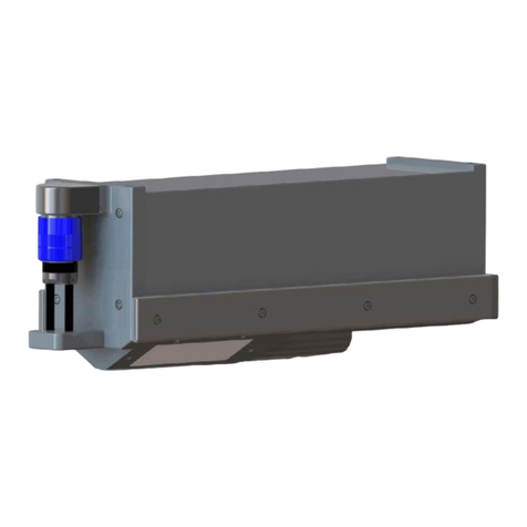
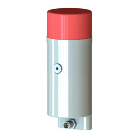
IMAGENEX 853 User manual

853 ES with Data Logger
445-076 JANUARY 2011-REVISED MAY 2017
Specifications subject to
IMAGENEX MODEL 853
SCIENTIFIC ECHO SOUNDER with DATA LOGGER
APPLICATIONS: FEATURES:
•Seaglider Installation •Programmable
•ROV, AUV & UUV •High performance
•Offshore Oil & Gas •Low power
•Surveying •Simple set-up and installation
•Scientific Research •Digital telemetry
•Fisheries Research •25, 50 or 100 m operation
•Compact size
•Communication format available to user
•USB Data download
Copyright ©2011 - 2019
change without notice www.imagenex.com Imagenex Technology Corp.

853 ES with Data Logger 2
445-076 www.imagenex.com
HARDWARE NS:SPECIFICATIO
FREQUENCY 120 kHz or Optional 300 kHz
TRANSDUCER Conical
TRANSDUCER BEAM WIDTH 10°
TRANSDUCER
SOURCE LEVEL B re 1 μPa @ 1 m (nominal)210 d
TRANSDUCER
RECEIVE SENSITIVITY -180 dB re 1 V/μPa (nominal)
RECEIVE BANDWIDTH 10 kHz
PULSE LENGTH 100 μs
MAXIMUM INPUT LEVELS B Gain: 35 mVRMSwith 20 d
with 40 dB Gain: 3.5 mVRMS
NOISE FLOOR VRMSwith 40 dB Gain: -96 dB re 1
RANGE BINS 200
DATA STORAGE ays before Download200 D
MIN. DETECTABLE RANGE 0.5 m
MAX. DETECTABLE RANGE 100 m
MAX. OPERATING DEPTH 1000 m
MAX. CABLE LENGTH 15 m (RS-232), 3 m (USB)
TELEMETRY/
PROGRAMMING INTERFACE 15.2 kbps (or as ordered)RS-232 Serial Interface @ 1
DOWNLOAD INTERFACE USB
CONNECTORS Impulse IEW55-1004-BCR / IEW55-1006-BCR
POWER SUPPLY e only)9 – 32 VDC at less than 0.25 Watts (Glider mod
TEMPERATURE -5 to +35 °C (operational)
-40 to +50 °C (storage)
DIMENSIONS See drawing
WEIGHT: In Air
In Water 0.55 kg (1.2 lbs)
~ 1 kg (2.2 lbs)
~
MATERIALS 6061-T6 Aluminum, PVC
FINISH Hard Anodize
SOFTWARE ONS: Programming/Download/Viewing
SPECIFICATI program: Win853.exe
WINDOWS™OPERATING SYSTEM Windows™XP, Vista, 7, 8, 10
MODES Normal (interrogate to ping)
Glider (one ping every 4 seconds)
Stand Alone (one ping per second)
RANGE SCALES 25 m, 50 m, 100 m
FILE FORMAT (filename).853
RECOMMENDED ER 4
sk
resolution
MINIMUM COMPUT
REQUIREMENTS:
2 GHz Pentium
256 MB RAM
20 GB Hard Di
1024 x 768 screen

ORDERING
INFORMATION:
1000 m UNIT Standard 853-000-140
300 kHz Option -049
Product and company names listed are trademarks or trade names of their respective companies.
853 ES with Data Logger 3
445-076 www.imagenex.com

16JUL15
Model 853 Serial Interface Specification Page 1 of 13
IMAGENEX TECHNOLOGY CORP.
MODEL 853 SCIENTIFIC ECHO SOUNDER WITH DATA LOGGER
SERIAL INTERFACE SPECIFICATION (v1.03)
OVERVIEW
The Model 853 Scientific Echo Sounder is a self contained, programmable digital echo
sounder with built in flash memory data storage. Programmable parameters include
operating mode, acoustic range scale, receiver gain, dive number, dive type and ping
timestamp. The unit is powered from 24VDC and is programmed using an RS-232 serial
communications port connected to the power/data connector. Recorded echo sounder data
can be downloaded from the internal SD flash memory card via the self powered USB
connector.
The 853 has three operating modes, “Normal”, “Glider” and “Stand Alone”:
In Normal mode, the echo sounder pings when requested by the serial interface. The
settings for each ping are based on the current programmable range and gain settings. The
ping rate is dependent on the interrogation rate of the serial interface.
In Glider mode, the programmable settings for range and gain are used, in addition, the
echo data can be sampled periodically via the serial interface. Echo data from each ping is
stored to the internal flash memory. The ping rate is once every four seconds.
In Stand Alone mode, the echo sounder runs unattended using the programmable range
and gain settings. Echo data is stored on a ping by ping basis to the internal flash
memory. The ping rate is once per second.
The Switch Data Command (described below) is used for programming the unit and
requesting echo data. To program the unit or request echo data, the Switch Data
Command string is sent via a serial command program at a baud rate of 9600 bps, No
Parity, 8 Data Bits and 1 Stop Bit (other baud rates are available).
When the Switch Data command is accepted, the 853 responds with a 256 byte IKX
Return Data packet or an 18 byte ILX Return Data packet. A message type of IKX must
be selected to change any of the programmable settings.

16JUL15
Model 853 Serial Interface Specification Page 2 of 13
OPERATION
On power-up, the echo sounder defaults to Normal mode and waits for a Switch Data
Command from the serial interface. If a Glider or Stand Alone mode command is sent,
the unit will ping immediately then write the 256 byte IKX ping return data to a file on
the SD card (see filename details below). It will continue to ping once every four seconds
(Glider mode) or once per second (Stand Alone mode). Successive Glider mode or Stand
Alone mode pings are appended to the file until a new filename is issued. Sending a
Normal mode command tells the unit to stop recording.
New for version 1.03:
The files are now stored in a sub-directory named "ES853" on the SD card with a
maximum file limit of 65536.
New for version 1.02:
853 Echo Sounders are now available with the standard frequency of 120kHz or
with an optional frequency of 300kHz. Byte 11 of the 'IKX' Echo Sounder Return
Data packet reflects the configured frequency (0=120kHz, 1=300kHz).
Byte 5 of the Switch Data Comand is now reserved and must have a value of 0.
The file creation timestamps written to the SD card now contain the correct date
and time fields from the the Switch Data Command.

16JUL15
Model 853 Serial Interface Specification Page 3 of 13
New for version 1.01:
The filename is no longer an automatically generated sequential number.
It is now derived from the following two new fields (bytes 9-11) of the
Switch Data Command:
“Dive Number”
“Dive Type”
The filename takes the form:
ESnnnnnT.853, where:
nnnnn = Dive Number (1 to 32767)
T = Dive Type (A = descent, B = ascent)
Dive number must be incremented by the user to create new filenames.
A timestamp has been added to the ping header. The date and time must
be sent to the unit using the appropriate fields in the Switch Data Command.
The 853 will keep track of the time until the next command. Each ping header
in the file will contain a unique time.

16JUL15
Model 853 Serial Interface Specification Page 4 of 13
SWITCH DATA COMMAND
The 853 accepts up to 27 bytes of switch data from the serial interface and must see the
switch data header (2 bytes: 0xFE and 0x44 HEX) in order to process the switches. The
unit will stop accepting switch data when it sees the termination byte (0xFD HEX). The
termination byte must be present to process the switches.
Note: the Termination Byte is the only switch value allowed
to have a value of 0xFD. All other switches should be set
higher or lower than 0xFD (253 Decimal) so they are not
interpreted as a termination byte!
Byte #
Description
0 –7
0xFE
0x44
Head
ID
Range
Gain
Reserved
0
Pulse
Length
Mode
8 –15
Message
Type
Dive No.
HI
Dive No.
MID
Dive No.
LO
Day
Month
Year
HI
Year
LO
16 –23
Hours
Minutes
Seconds
MSec
HI
MSec
LO
Reserved
0
Reserved
0
Reserved
0
24 –26
Switch
Delay
Reserved
0
Term.
0xFD
BYTE DESCRIPTIONS
Note: All Byte values are shown in decimal unless noted with a '0x' (hexadecimal) prefix.
Byte 0 Switch Data Header (1st Byte)
Always 0xFE (254 decimal)
Byte 1 Switch Data Header (2nd Byte)
Always 0x44 (68 decimal)
Byte 2 Head ID
0x1D only (29 decimal)
Byte 3 Range
0 = 25 Meters for future use
1 = 50 Meters for future use
2 = 100 Meters
Byte 4 Gain
1 = 20dB
2 = 40dB

16JUL15
Model 853 Serial Interface Specification Page 5 of 13
SWITCH DATA COMMAND (con't)
Byte 5 Reserved
Always 0
Byte 6 Pulse Length
0 = 100 microseconds
Byte 7 Operating Mode
0 = Normal mode
Each ping requires a separate Switch Data Command to be sent. Ping rate
is dependent on the interrogation rate of the commanding program and the
acoustic range time of the ping. Echo data is not stored to the internal flash
memory in Normal mode.
1 = Glider mode
Ping rate is once every four seconds, ILX serial data can be sampled at any
time. Echo data is stored to the internal flash memory every ping.
2 = Stand Alone
For unattended echo sounder operation, ping rate is once per second. ILX
serial data can be sampled at anytime. Echo data is stored to the internal
flash memory every ping.
Byte 8 Message Type
0 = 256 byte standard ‘IKX’ return
1 = 18 byte sample ‘ILX’ return
Byte 9-11 Dive Number and Dive Type
Increment Dive Number to create a new file.
All pings are appended to the file until a new filename is created.
Filename: ESnnnnnT.853
Byte 9
Byte 10
Byte 11
7
6
5
4
3
2
1
0
7
6
5
4
3
2
1
0
7
6
5
4
3
2
1
0
0
T
0
0
0
0
HI
0
MID
0
LO
Dive Type
(T = 0 or 1)
Dive Number
(1 to 32767)
Dive Type (T):
0 = A = Descent
1 = B = Ascent
Dive Number (nnnnn):
1 to 32767

16JUL15
Model 853 Serial Interface Specification Page 6 of 13
SWITCH DATA COMMAND (con't)
Byte 9 = [(Dive Type & 0x01)<<6] | [(Dive Number & 0x00C000)>>14]
Byte 10 = (Dive Number & 0x003F80)>>7
Byte 11 = Dive Number & 0x00007F
Bytes 12 through 20 contain the interrogation timestamp. The 853 will add the 'ping' time
offset to this timestamp as well as automatically increment the time by 1 or 4 seconds
each ping depending on the mode (Stand Alone or Glider).
Byte 12 Day
1 to 31
Byte 13 Month
1 to 12
Byte 14-15 Year
2012 and higher
Byte 14
Byte 15
7
6
5
4
3
2
1
0
7
6
5
4
3
2
1
0
0
Year (HI)
0
Year (LO)
Byte 14 = (Year & 0x3F80)>>7
Byte 15 = Year & 0x7F
Byte 16 Hours
0 to 23
Byte 17 Minutes
0 to 59
Byte 18 Seconds
0 to 59
Byte 19-20 Milliseconds
0 to 999
Byte 19
Byte 20
7
6
5
4
3
2
1
0
7
6
5
4
3
2
1
0
0
Milliseconds (HI)
0
Milliseconds (LO)
Byte 19 = (Milliseconds & 0x3F80)>>7
Byte 20 = Milliseconds & 0x7F

16JUL15
Model 853 Serial Interface Specification Page 7 of 13
SWITCH DATA COMMAND (con't)
Byte 21-23 Reserved
Always 0
Byte 24 Switch Delay
The echo sounder can be commanded to pause (from 0 to 510 msec)
before sending its return data to allow the commanding program
enough time to setup for serial reception of the return data.
0 to 255 in 2 msec increments
Byte 24 = delay_in_milliseconds/2
Do not use a value of 253!
Byte 25 Reserved
Always 0
Byte 26 Termination Byte
The echo sounder will stop looking for Switch Data when it sees this byte.
Always 0xFD (253 decimal)

16JUL15
Model 853 Serial Interface Specification Page 8 of 13
RETURN DATA
After a Switch Data Command, the 853 replies with a serial return data packet. The
packet size depends on the value of “Message Type” (Byte 8 of the Switch Data
Command). The standard return (Message Type = 0) is a 256 byte “IKX” packet
consisting of a 55 byte header, 200 range bins of echo data and a termination byte value
of 0xFC. Each range bin contains a 7-Bit logarithmic value referenced to a 1 Volt peak-
peak signal, in the form 20*LOG(signal level/1V peak-peak). Signals from 1 microvolt to
1 volt peak-peak are represented, giving a span of 120dB (0 to -120dB).
Note: all numbers are negative but are stored as a positive value (i.e. -120dB is stored as
120)
Byte #
Header Description
0 to 9
ASCII
’I’
ASCII
’K’
ASCII
’X’
Head ID
0x1D
Serial
Status
Ping
Number
HI
Ping
Number
MID-HI
Ping
Number
MID-LO
Ping
Number
LO
Range
10 to 19
Gain
Frequency
Pulse
Length
Mode
Ping
Rate
HI
Ping
Rate
LO
Reserved
0
Reserved
0
Reserved
0
Dive No.
HI
20 to 29
Dive No.
MID
Dive No.
LO
Day
Month
Year
HI
Year
LO
Hours
Minutes
Seconds
MSec
HI
30 to 39
MSec
LO
Reserved
0
Reserved
0
Reserved
0
Reserved
0
Reserved
0
Reserved
0
Reserved
0
Reserved
0
Reserved
0
40 to 49
Reserved
0
Reserved
0
Reserved
0
Reserved
0
Reserved
0
Reserved
0
Reserved
0
Reserved
0
Reserved
0
Reserved
0
50 to 54
Reserved
0
Reserved
0
Reserved
0
Reserved
0
Reserved
0
Byte #
Echo Data Description
55 to 254
Logarithmic Echo Data
(200 range bins)
signal level = 10 ^ -(range bin value/20) volts peak-peak
Byte #
Termination Description
255
Terminator
0xFC
Note: in Glider and Stand-Alone modes, the 256 byte IKX data packet
is stored to the internal flash memory after each ping

16JUL15
Model 853 Serial Interface Specification Page 9 of 13
RETURN DATA (con’t)
IKX HEADER BYTE DESCRIPTION
Note: All Byte values are shown in decimal unless noted with a '0x' prefix.
N= total number of return bytes
Byte 0 - 2 Imagenex Return Data Header
ASCII ‘IKX’
Byte 3 Head ID
Always 0x1D
Byte 4 Serial Status
Bit 0 - 0
Bit 1 - 0
Bit 2 - 0
Bit 3 - 0
Bit 4 - 0
Bit 5 - 0
Bit 6 - 1 = Switches Accepted
Bit 7 - 1 = Character Overrun
Byte 5-8 Ping Number
Increments by one every ping
Byte 5
Byte 6
Byte 7
Byte 8
7
6 –0
7
6 –0
7
6 –0
7
6 –0
0
HI
0
MID-HI
0
MID-LO
0
LO
Ping Number
Ping Number = [(Byte 5 & 0x7F)<<21] | [(Byte 6 & 0x7F)<<14] |
[(Byte 7 & 0x7F)<<7] | (Byte 8 & 0x7F)
Byte 9 Range
0 = 25 Meters
1 = 50 Meters
2 = 100 Meters
Byte 10 Gain
1 = 20dB
2 = 40dB

16JUL15
Model 853 Serial Interface Specification Page 10 of 13
RETURN DATA (con’t)
Byte 11 Frequency
0 = 120kHz
1 = 300kHz
Byte 12 Pulse Length
0 = 100 microseconds
Byte 13 Mode
0 = Normal mode
1 = Glider mode
2 = Stand Alone mode
Byte 14-15 Ping Rate
Repetition rate in milliseconds
Byte 14
Byte 15
7
6
5
4
3
2
1
0
7
6
5
4
3
2
1
0
0
Ping Rate (HI)
0
Ping Rate (LO)
Ping Rate = [(Byte 14 & 0x7F)<<7] | (Byte 15 & 0x7F), in milliseconds
Byte 16-18 Reserved
Always 0
Byte 19-21 Dive Number and Dive Type
Byte 19
Byte 20
Byte 21
7
6
5
4
3
2
1
0
7
6
5
4
3
2
1
0
7
6
5
4
3
2
1
0
0
T
0
0
0
0
HI
0
MID
0
LO
Dive Type
(T = 0 or 1)
Dive Number
(1 to 32767)
Dive Type = (Byte 19 & 0x40)>>6
Dive Number = [(Byte 19 & 0x03)<<14] |
[(Byte 20 & 0x7F)<<7] |
(Byte 21 & 0x7F)
Bytes 22 through 30 contain the current ping timestamp:
Byte 22 Day
1 to 31

16JUL15
Model 853 Serial Interface Specification Page 11 of 13
RETURN DATA (con’t)
Byte 23 Month
1 to 12
Byte 24-25 Year
2012 and higher
Byte 24
Byte 25
7
6
5
4
3
2
1
0
7
6
5
4
3
2
1
0
0
Year (HI)
0
Year (LO)
Year = [(Byte 24 & 0x7F)<<7] | (Byte 25 & 0x7F)
Byte 26 Hours
0 to 23
Byte 27 Minutes
0 to 59
Byte 28 Seconds
0 to 59
Byte 29-30 Milliseconds
0 to 999
Byte 29
Byte 30
7
6
5
4
3
2
1
0
7
6
5
4
3
2
1
0
0
Milliseconds (HI)
0
Milliseconds (LO)
Milliseconds = [(Byte 29 & 0x7F)<<7] | (Byte 30 & 0x7F)
Byte 31-54 Reserved
Always 0
Byte 55-254 Logarithmic Echo Data
200 range bins
signal level = 10 ^ -(range bin value/20) volts peak-peak
Byte 255 Termination Byte
0xFC

16JUL15
Model 853 Serial Interface Specification Page 12 of 13
RETURN DATA (con’t)
The following is the description of the 18 byte ILX packet which is output in response to
a Switch Data Command string with Message Type = 1. This output contains 8 range bins
of echo data covering the first 40 meters in range, each range bin contains a 5m sample.
Byte #
Header Description
0 to 8
ASCII
’I’
ASCII
’L’
ASCII
’X’
Head ID
0x1D
Serial
Status
Ping
Number
HI
Ping
Number
MID-HI
Ping
Number
MID-LO
Ping
Number
LO
Byte #
Echo Data Description
9-16
Logarithmic Echo Data
(8 range bins)
signal level = 10 ^ -(range bin value/20) volts peak-peak
Byte #
Termination Description
17
Terminator
0xFC
ILX HEADER BYTE DESCRIPTION
Note: All Byte values are shown in decimal unless noted with a '0x' prefix.
N= total number of return bytes
Byte 0 - 2 Imagenex Return Data Header
ASCII ‘ILX’
Byte 3 Head ID
Always 0x1D
Byte 4 Serial Status
Bit 0 - 0
Bit 1 - 0
Bit 2 - 0
Bit 3 - 0
Bit 4 - 0
Bit 5 - 0
Bit 6 - 1 = Switches Accepted
Bit 7 - 1 = Character Overrun

16JUL15
Model 853 Serial Interface Specification Page 13 of 13
RETURN DATA (con’t)
Byte 5-8 Ping Number
Increments by one every ping
Byte 5
Byte 6
Byte 7
Byte 8
7
6 –0
7
6 –0
7
6 –0
7
6 –0
0
HI
0
MID-HI
0
MID-LO
0
LO
Ping Number
Ping Number = [(Byte 5 & 0x7F)<<21] | [(Byte 6 & 0x7F)<<14] |
[(Byte 7 & 0x7F)<<7] | (Byte 8 & 0x7F)
Byte 9-16 Logarithmic Echo Data
8 range bins
signal level = 10 ^ -(range bin value/20) volts peak-peak
Byte 17 Termination Byte
0xFC

Imagenex Technology Corp. ©2013
Model 853 Care Guide and Environmental Specification.doc Page 1 of 2
Imagenex Model 853 Care Guide and Environmental Specification
This document describes general care for the Imagenex Model 853 Scientific Echo Sounder with Data
Logger and its' operating environmental specifications including depth and temperature.
General Care and Usage
Model 853 Echo Sounders are designed to be operated in many types of operating environments. However
to prolong the life of the equipment, simple maintenance is required.
Routine Maintenance
Fresh Water Rinse After each immersion of the underwater unit, rinse the echo sounder
thoroughly in fresh water. This will prevent the accumulation of salt or
other contamination, and help prevent corrosion of the aluminum and /
or stainless steel parts.
Clean Transducer Face The black epoxy transducer face should be cleaned with a detergent
solution such as dishwashing liquid to remove any oil, grease, or other
deposits which may reduce the acoustic performance of the unit.
Clean and Lubricate Connectors The cables and connectors should be washed and coated with a thin
film of silicon grease to protect the rubber. The connectors should be
protected from prolonged exposure to sunlight, ozone, solvents,
hydrocarbon greases, and oils to avoid deterioration of the rubber.
Underwater Unit Storage After being thoroughly cleaned and dried, the underwater unit should
be stored in a dry, stable location to prevent moisture corrosion and
damage from impact.
Cable Storage The cables should be protected from prolonged exposure to sunlight,
ozone, solvents, hydrocarbon greases, and oils to avoid deterioration of
the rubber.
Do not use any solvents on the cables or underwater unit as they will compromise the physical
integrity of the echo sounder.
Service
There are no user serviceable components in the echo sounder and as such all repairs must be directed to:
Imagenex Technology Corp.
209-1875 Broadway Street
Port Coquitlam, BC, Canada
V3C 4Z1
Tel : (604)944-8248
Fax : (604)944-8249
web: www.imagenex.com
email: imagenex@shaw.ca

Imagenex Technology Corp. ©2013
Model 853 Care Guide and Environmental Specification.doc Page 2 of 2
Safety
Before each use, inspect the transducer face for impact damage. Inspect the connectors on both the echo
sounder and the cables for any damage such as bent or broken pins, or cuts in the cable. Ensure that the
mating connections are secure and that the locking sleeves are in place.
Operational Environmental Specification
While the Model 853 is designed to operate in a wide variety of environments, there are limitations.
Table 1 - Model 853 (853-000-140) Environmental Specification
Minimum
Maximum
Units
Temperature
-5
35
C
Depth
0
1000
m
Storage
-40
50
C
Salinity 1
0
40
ppt
1 The operation specification on Salinity is for acoustic properties only (i.e. the speed of sound in
the medium). Salinity has no effect on mechanical operations if the unit is thoroughly cleaned
after use.

1
234
5678
910
1
234
5678
910
A
B
C
D
E
F
G
H
A
B
C
D
E
F
G
H
Title:
Document Number: Rev
Date: Sheet of
853 Echo Sounder Cable Dra ing
853-200-283 01
March 20, 2012 1 1
IMAGENEX TECHNOLOGY CORP.
6
3
21
54
IE55-1206-CCP
Face Vie
1
IE55-1206-CCP
3
2
4
5
6
VIN - / RS232 COM
TX232
RX232
VIN +
21
43
IE55-1204-CCP
Face Vie
1
IE55-1204-CCP
3
2
4
VCC
Data +
GND
Data -
USB Type 'A'
1
3
2
4
WHT
BLK
RED
GRN
DB9 (F)
To RS232
Serial Port
3
2
5
Cat 5e.
(10ft)
VIN +
TX232
RX232
VIN - VIN -
VIN +
TX232
RX232
VIN +
VIN -
VIN +
BLK #18
RED #18
USB Data Cable
BRN
BRN / WHT
BLU
BLU / WHT
GRN / WHT
GRN
ORG
ORG / WHT
RED
WHT
GRN
BLK
Table of contents
Other IMAGENEX Marine Equipment manuals
Popular Marine Equipment manuals by other brands

Simrad
Simrad ER60 - REV B Operator's manual

Simrad
Simrad ES60 - REFERENCE MANUAL REV H Reference manual

Whale
Whale orca auto 1300 Installation and operation manual

Simrad
Simrad NSO-II installation manual

Raymarine
Raymarine ST70 Instrument operating guide

WÄRTSILÄ
WÄRTSILÄ ELAC LAZ 5200 operating instructions