auto maskin LT Series User manual
Publication P/N 1500119
User Manual
Marine Watch LT Series
LT-ONE Alarm Panel
LT-ACE Annunciator Panel

Table of contents
1 About this Manual 3
1.1 Intended Audience 3
1.2 Responsibilities 3
1.3 Revisions 3
2 Welcome to Marine Watch LT 4
2.1 Introduction 4
2.2 Minimum Installation 4
2.2.1 LT-ONE Alarm Panel 4
2.2.2 LT-ACE Annunciator Panel 4
2.3 Web Server 5
2.4 Hardware Connectivity and Sensors 5
2.5 Connector Kit 5
2.6 Connector Pin-reference 6
2.6.1 LT-ONE Alarm Panel 6
2.6.2 LT-ACE Annunciator Panel 7
2.6.3 Crimp Tool 7
2.7 Third-party Communication Interface 8
3 User Interface 9
3.1 Header Information 9
3.1.1 Change the Panel Name 9
3.2 Operator Interface 9
3.2.1 Buttons 10
3.2.2 Touch Screen 10
3.2.3 Buzzer 10
3.3 Menu 11
3.4 Alarm List 11
3.4.1 Alarm List Description 12
3.5 Alarm Pages 13
3.5.1 The Alarm Grid Page 13
Alarm Grid Description 14
4 Firmware Upgrade 14
5 LT-ONE Alarm Panel Configuration 15
5.1 Introduction 15
5.2 Load and Save Configuration 15
5.3 Configuration Steps 15
5.3.1 Channel Configuration 15
5.3.2 Assigning the Channel in a
Template 15
5.4 Login to the Panel 16
5.4.1 Connection and Login 16
5.5 Flexible I/O Configuration 16
5.6 Switch Channel Configuration 17
5.6.1 Configure an Alarm Channel 18
5.6.2 Configure a Warning Channel 19
5.7 Analog Channel Configuration 19
5.8 Pages and Templates 21
5.8.1 Choose a Template Page 21
5.8.2 Assign Channels in the Template
Page 22
6 LT-ACE Annunciator Panel Configuration
23
6.1 Connect to LT-ONE Alarm Panel 23
6.2 Network Address 23
6.3 Web Interface 24
Page 2 (24)

1 About this Manual
1.1 Intended Audience
This manual has been published primarily for professionals and qualified personnel. The
user of this material is assumed to have basic knowledge in marine systems and must be
able to carry out related electrical work.
Work on the low voltage circuit should only be carried out by qualified and experienced
personnel. Installation or work on the shore power equipment must only be carried out by
electricians authorized to work with such installations.
1.2 Responsibilities
It is the sole responsibility of the installer to ensure that the installation work is carried out
in a satisfactory manner, that it is operationally in good order, that the approved material and
accessories are used and that the installation meets all applicable rules and regulations.
Auto-Maskin continuously upgrades its products and reserves the right to make
changes and improvements without prior notice.
All information in this manual is based upon information at the time of printing. For updated
information, please contact your local distributor.
The crossed-out wheeled bin symbol indicates that the item should be
disposed of separately. The item should be handed in for recycling in
accordance with local environmental regulations for waste disposal.
By separating a marked item, you will help reduce the volume of waste
sent to incinerators or land-fill and minimize any potential negative impact
on human health and the environment.
1.3 Revisions
This User Manual is valid for the following firmware version of the Marine Watch LT Series,
LT-ONE Alarm Panel and LT-ACE Annunciator Panel.
Edition
Firmware Version
Release
Release
3.10 P6
March 2022
User Manual revision: 7 March 2022
Page 3 (24)

2 Marine Watch LT Series
2.1 Introduction
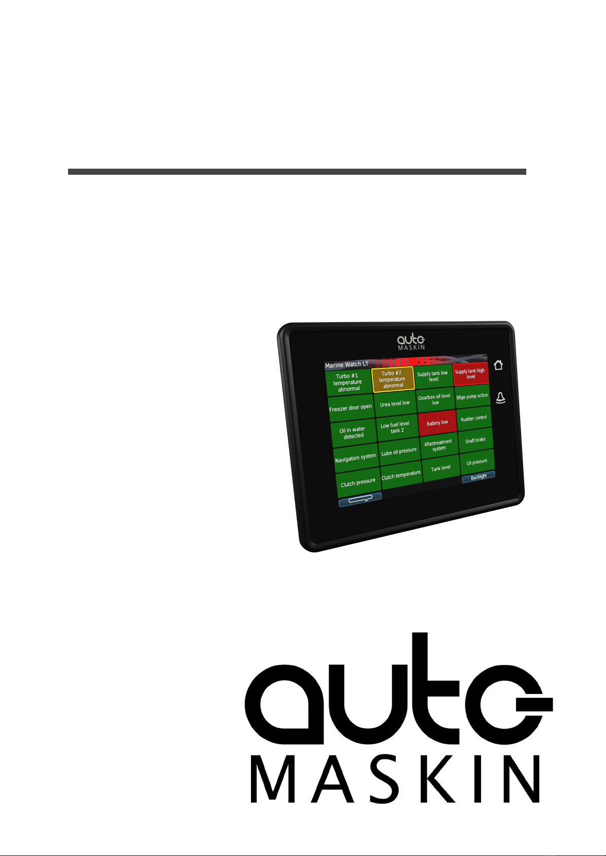
The Marine Watch LT Series is a compact yet powerful alarm system. The front panel is a
touch screen, and the main page typically displays a grid of maximum 20 rectangles. Each
rectangle represents the status of an alarm (or warning) channel.
In the event of a warning or an alarm, the corresponding rectangle indicates clearly with a
flashing behaviour, and the buzzer sounds. The event is also indicated in the standard Alarm
List, where it can be acknowledged.
The panel can be configured to display up to 9 pages. Each page layout is based on a
template, and each page can display any of the available templates.
All base I/O interfaces are built into the panel. See the datasheet for a complete overview.
The panel can also read data from a J1939 CAN bus.
Optional I/O expansion for hardwired signals can be added, typically in the form of
Auto-Maskin RIO units.
Multiple LT-ACE Annunciator Panels can be added in a standard Ethernet network.
2.2 Typical Installation
The typical Marine Watch LT installation consists of one LT-ONE Alarm Panel, and one or
several LT ACE Annunciator Panels. Signals are connected to the Alarm Panel either
hardwired, on the J1939 CAN bus or from one of the many supported RIO expansion I/O
units.
Additional LT-ACE Annunciator Panels can easily be added in a standard Ethernet network
at any time. Once connected, these Annunciator Panels configure themselves from the
LT-ONE Alarm Panel.
2.2.1 LT-ONE Alarm Panel
The Marine Watch LT-ONE Alarm Panel is
connected to all I/O.
2.2.2 LT-ACE Annunciator Panel
Any number of Marine Watch LT-ACE
Annunciator Panels can be connected in a
network.
The Annunciator Panels require no
manual configuration and are always in
sync with the configuration of the LT-ONE
Alarm Panel.
Page 4 (24)
2.3 Web Server
The Marine Watch LT-ONE Alarm Panel configuration is performed with the built-in web
server by logging in using the correct IP address. See the Configuration section for more
information.
Note! Configuration changes for the LT-ONE Alarm Panel automatically applies to all
networked and connected LT-ACE Annunciator Panels.
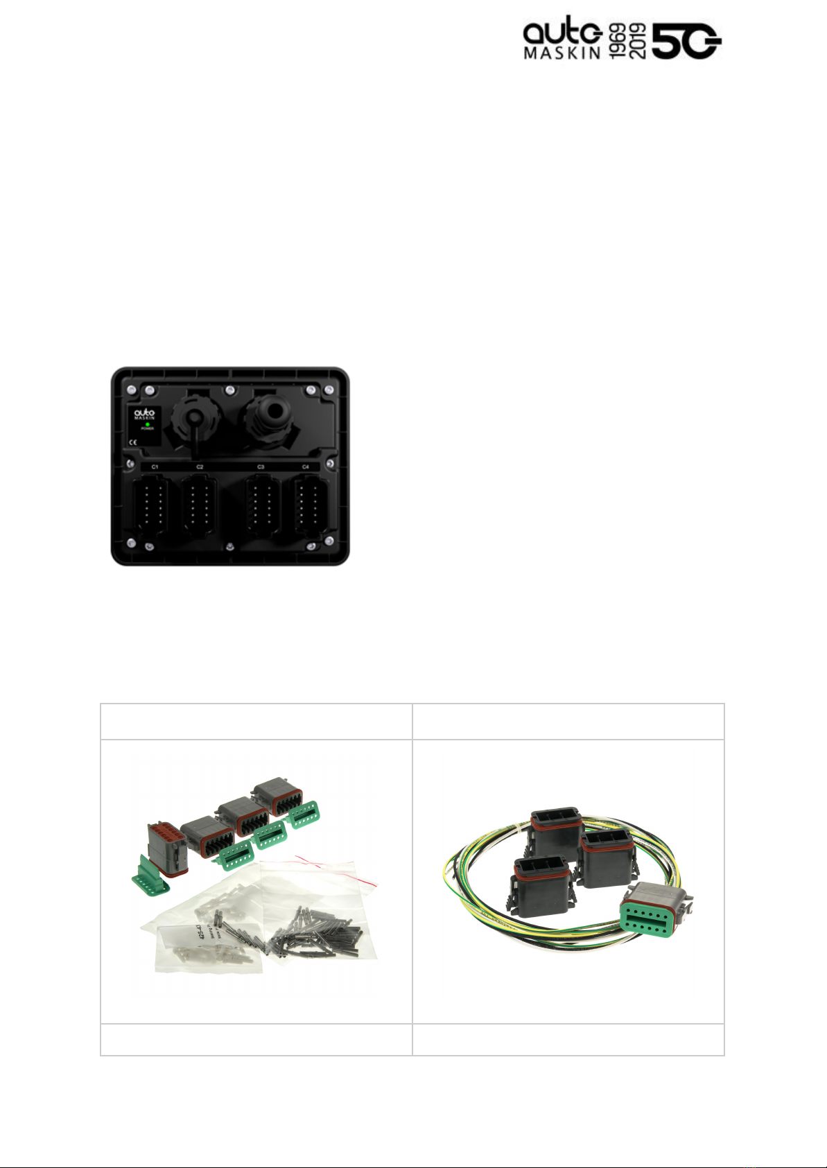
2.4 Hardware Connectivity and Sensors
The rear side of the Panel has the following interfaces.
Connectors C1 - C4
■ All I/O shall be interfaced to the
Deutsch™ DT connectors.
USB interface
■ Save and load configuration files
■ Upload new firmware
RJ45 Ethernet
■ Configure the Alarm Panel
■ Communicate on Ethernet
2.5 Connector Kit
Note that the Marine Watch LT panels do not include the four mating Deutsch™ connectors
and crimp pins. These are available in kits as follows.
LT-ONE Alarm Panel connector kit
LT-ACE Annunciator Panel connector kit
P/N 1006479
P/N 1006946
Page 5 (24)

2.6 Connector Pin-reference
Each of the four Deutsch™ DT-connectors has 12 pins and are referenced in the table
below.
Example: C1.11 = connector 1, pin 11
2.6.1 LT-ONE Alarm Panel
Power Supply
C1.11
+12/24 VDC supply
C1.12
0 V supply
C1.3
Ground connection1
RIO Link Interface
C1.5
Low
C1.6
High
J1939 CAN bus Interface
C1.7
CAN 1 high
C1.8
CAN 1 low
C1.9
CAN shield
C2.10
CAN 2 high (I/O #20 )
2
C2.11
CAN 2 low (I/O #21 )
3
Common Alarm/Warning Relay4
C2.1
NC
C2.2
Common
C2.3
NO
Relay #1
C2.4
NC
C2.5
Common
C2.6
NO
Relay #2
4The relay is activated when no active event
3The alternative function is binary input
2The alternative function is binary input
1Connected internally to C1.9 and C4.3
C2.7
NC
C2.8
Common
C2.9
NO
Magnetic Pickup
C4.1
A
C4.2
B (I/O #18 )
5
Modbus RTU RS-485
C4.3
Shield
C4.4
Low
C4.5
High
Thermistor
C4.6
Thermistor #1 A
C4.7
Thermistor #1 B
C4.8
Thermistor #1 C
C4.9
Thermistor #2 A
C4.10
Thermistor #2 B
C4.11
Thermistor #2 C
Flexible I/O
C1.1
I/O #1
C1.2
I/O #26
C1.4
I/O #3
C1.10
I/O #4
6Configurable as flexible I/O or as 0V
reference
5Configurable as flexible I/O or as 0V
reference
Page 6 (24)

C2.12
I/O #57
C3.1
I/O #6 / sensor power8
C3.2
I/O #7
C3.3
I/O #8
C3.4
I/O #9
C3.5
I/O #10
C3.6
I/O #11
C3.7
I/O #12
C3.8
I/O #13
C3.9
I/O #14
C3.10
I/O #15
C3.11
I/O #16
C3.12
I/O #17
C4.2
I/O #189
C4.12
I/O #19
2.6.2 LT-ACE Annunciator Panel
Power Supply
C1.11
+12/24 VDC supply
C1.12
0 V supply
C1.3
Ground connection
Switch Input
C1.1
Switch input #1
C1.2
Switch input #2
9Configurable as flexible I/O or as 0V
reference
8Configurable as flexible I/O or as supply for
0-5 V sensor
7Configurable as flexible I/O or as 0V
reference
C1.4
Switch input #3
Common Alarm/Warning Relay10
C2.1
NC
C2.2
Common
C2.3
NO
2.6.3 Crimp Tool
Use the correct crimp tool for the
connector’s pin- and wire assembly.
We recommend the Deutsch™
HDT-48-00.
10 The relay is activated when no active event
Page 7 (24)


3 User Interface
3.1 Header Information
The header consists of the following information.
■ The Panel name Marine Watch LT. The name can be changed in the configuration.
■ A common warning/alarm banner. The entire centre of the header is flashing for new
and unacknowledged events. It is not flashing if all events are acknowledged.
A new Warning is indicated with a yellow flashing banner, and a new alarm is indicated with
a red flashing banner. If there are warnings and alarms, then the alarm banner takes
precedence.
If the channels are acknowledged but still active, then the banner indicates without flashing.
Summarized:
Warning only
Alarm only
Warning and Alarm
New and
unacknowledged
Yellow banner,
flashing
Red banner,
flashing
Red banner,
flashing
Acknowledged
Yellow banner,
not flashing
Red banner,
not flashing
Red banner,
not flashing
3.1.1 Change the Panel Name
The default panel name is Marine Watch LT. It can be changed here.
3.2 Operator Interface
The operator interface consists of
■ Buttons
■ Touch screen, and
■ Buzzer
Page 9 (24)
3.2.1 Buttons
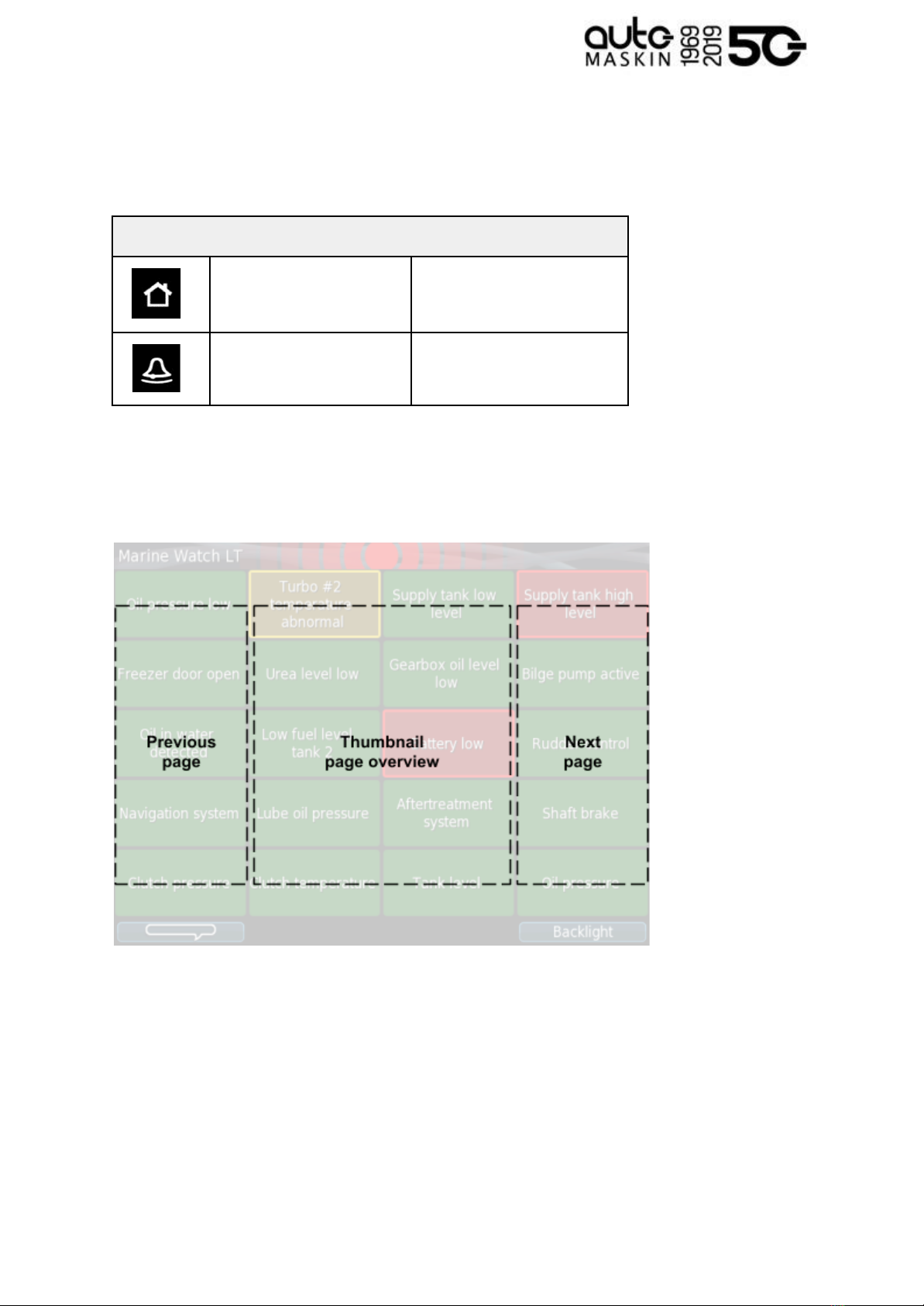
There are two physical buttons on the Marine Watch LT panel.
Operator Interface
Home Button
Toggle the view between
Alarm Pages and the Menu.
Alarm Button
Silence buzzer and show the
Alarm List.
3.2.2 Touch Screen
The touch screen is divided into three large touch navigation areas as follows.
If there is one page only, then pressing the Previous and Next page areas will have no effect.
3.2.3 Buzzer
The buzzer sounds for any new event, and is silenced when pressing the Alarm button (see
above).
Page 10 (24)
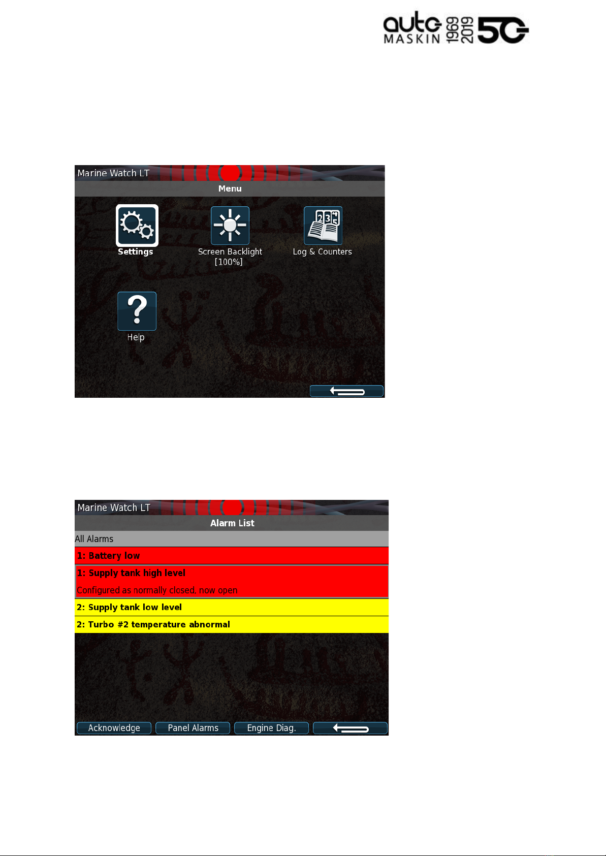
3.3 Menu
All operator settings, such as language selection, screen backlight, etc. is accomplished in
the built-in menu structure of the Marine Watch LT.
3.4 Alarm List
For the LT-ONE Alarm Panel, the Alarm List will show all alarms available. The LT-ACE
Annunciator Panel will show a combined Alarm List for all connected LT-ONE Alarm Panels.
Note! On the Marine Watch LT-ACE Annunciator Panels, the Alarm List will also show the
Page 11 (24)

Alarm Panel source. In order to acknowledge an alarm, the alarm need to be selected by the
operator and then acknowledged.
3.4.1 Alarm List Description
The events are colored differently depending on the status as below.
Alarm List
1: New active Alarm
Bold text, red background
1: Acknowledged active Alarm
Red background
1: Unacknowledged inactive Alarm
Bold red text, grey background
2: New active Warning
Bold text, yellow background
2: Acknowledged active Warning
Yellow background
2: Unacknowledged inactive Warning
Bold yellow text, gray background
The number prior to the event describes the severity; 1 for alarm and 2 for warning.
Page 12 (24)
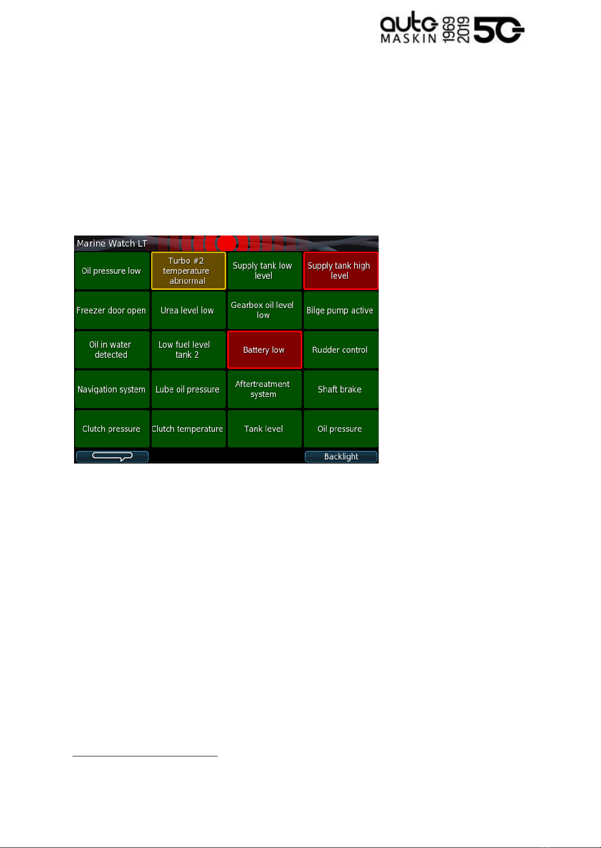
3.5 Alarm Pages
Depending on the configuration, the Marine Watch LT panel displays one or several (up to 9)
pages.
3.5.1 The Alarm Grid Page
Each rectangle represents the status of a binary/switch input channel, an analogue channel
or a J1939 CAN bus signal.
11
Each Alarm Grid page can display signal status for up to 20 channels. The rectangle can
hold up to three lines of text.
11 J1939 CAN bus configuration is not described in this manual
Page 13 (24)
Alarm Grid Description
The rectangles in the Alarm Grid Page can take the following forms.
Normal
Active,
unacknowledged
Flashing border
Active,
acknowledged
Inactive,
unacknowledged
Flashing border
4 Firmware Upgrade
A firmware upgrade can be accomplished using a USB memory stick or using the built-in
web server of the unit.
The latest released firmware can be downloaded from the Auto-Maskin web site.
Page 14 (24)

5 LT-ONE Alarm Panel Configuration
The configuration is solely required for the Marine Watch LT-ONE Alarm Panel.
Configuration changes are automatically applied to all networked LT-ACE Annunciator
Panels.
5.1 Introduction
This section covers the basic configuration of the binary/switch and analogue I/O-channels
of the Marine Watch LT-ONE Alarm Panel.
Note! The panel has sophisticated configuration options that far exceeds the use of the
panel as a basic alarm panel. This extended configuration is not typically used nor
necessary, and consequently is not covered in this manual.
For a complete configuration overview, see the 200E Series Configuration Manual on the
Auto-Maskin website.
5.2 Load and Save Configuration
The Marine Watch LT-ONE Alarm Panel can hold up to 50 configuration files.
The current configuration can be exported to either a USB memory stick or exported using
the web interface.
Likewise, any configuration can be uploaded to the Marine Watch LT-ONE Alarm Panel
using USB memory stick or the web interface.
Note! In order to apply a new configuration, the configuration need to be explicitly loaded.
5.3 Configuration Steps
There are two main steps in the configuration.
■ Channel configuration
■ Assigning the configured channel to a slot in a template
5.3.1 Channel Configuration
All channels – switches or analogue – shall be given a text description, a time delay, etc.
The Marine Watch LT supports flexible I/O, all I/O must be configured to the correct use; the
default use case is as Switch Input for all flexible I/O.
5.3.2 Assigning the Channel in a Template
The configured channel shall be assigned to a slot (a “location”) in a given template. See the
Template selection chapter.
Page 15 (24)

5.4 Login to the Panel
Before any configuration can be done one must log in to the webserver of the panel.
5.4.1 Connection and Login
Connect an Ethernet cable between a PC and the panel. In the URL-field of a web browser,
type the IP-address of the panel. The default IP address is 192.168.0.151.
Type the username and password as follows
■ Username: lt
■ Default password: 1234
Note! All units in a network must have a unique IP address. The IP address of the panel can
be changed using either the built-in web interface or using the panel menu.
5.5 Flexible I/O Configuration
The Marine Watch LT supports flexible I/O. A flexible I/O means the channel can be
configured to accept one of many different signal types.
Flexible I/O
Description
Switch Input
Regular switch input (0 / 24 V)
User Config Output
Configurable switch output (0 / 24 V)
4-20 mA Input
4 - 20 mA current input
Voltage Sensor Input12
0 - 32 V voltage input
To configure the channel, select home / lt-one / i/o configuration / flexible i/o / configure.
The image below is then displayed.
12 Prefer the 0V reference at pin C1.12
Page 16 (24)
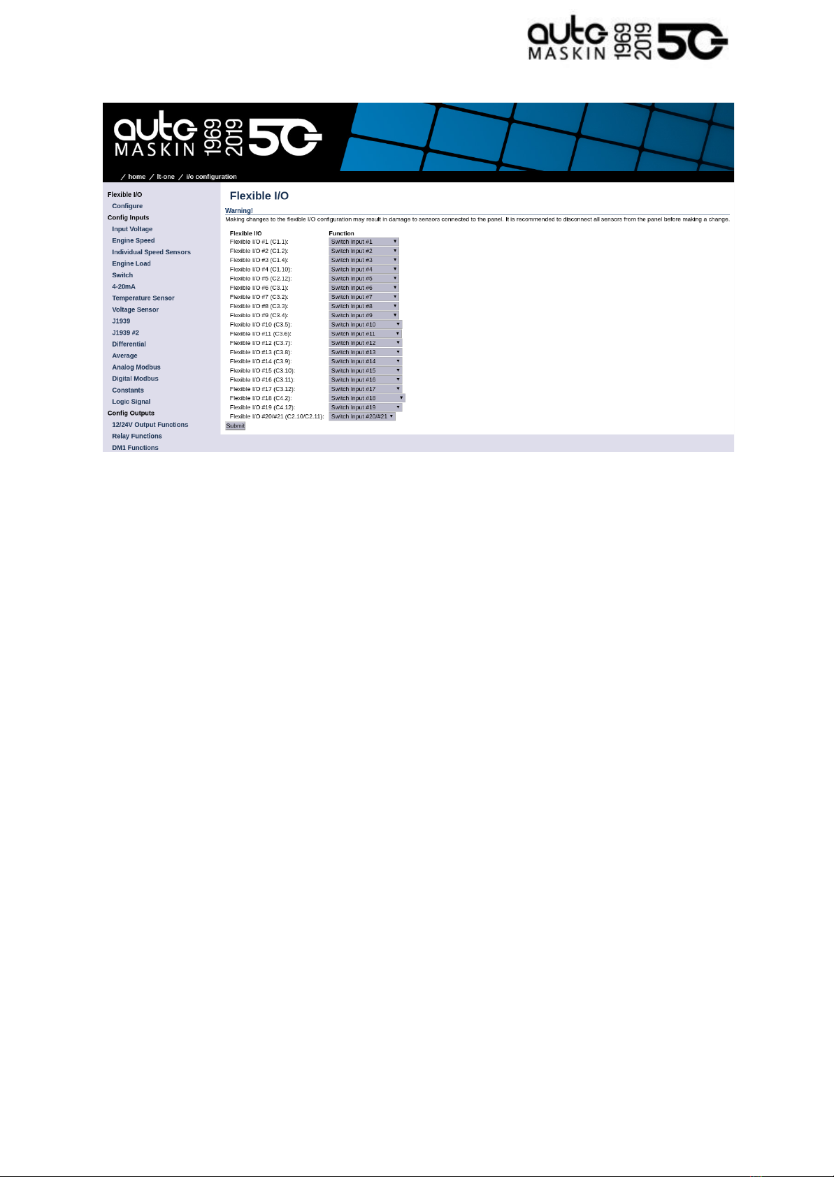
Note that the physical connector and pin reference (i.e. C1.4) for each I/O is given for each
channel.
Remember to press Submit to store the configuration.
5.6 Switch Channel Configuration
Select the menu item home / lt-one / i/o configuration / switch
The left margin lists 21 Switch Input channels. Select Switch Input #1.
The page should look similar to this:
Page 17 (24)

5.6.1 Configure an Alarm Channel
In this example, we are configuring Switch Channel #1 as an alarm channel. When the
event trigger, it will indicate in red.
In the Configure section from the above image, consider the following:
■assign custom name: This is where the channel is given a descriptive text.
○ Choose a language, then type the channel description. Finally, click the
Submit button.
○ In the left margin, select Switch Channel #1 item to return to the channel
configuration.
■Function: This shall be None. If any other function is selected here, then the
channel will not be used as an alarm channel.
■General: Channel Use shall be set to LT-ONE,RP,Event
■ Alarming:
○The Event shall be Alarm in this example.
○The Input State shall normally be Normally Closed (alarming when the switch
opens, or a wire breaks).
Page 18 (24)

○ The Delay Before Event [sec] is the time delay after the switch changes state
until the alarm activates. Typically a few seconds.
■ Finally, click the Submit button. The channel configuration is now stored in the panel.
5.6.2 Configure a Warning Channel
In this example, we are configuring Switch Channel #2 as a warning channel. When the
event trigger, it will indicate in yellow.
In the Configure section from the above image, consider the following:
■assign custom name: This is where the channel is given a descriptive text.
○ Choose a language, then type the channel description. Finally, click the
Submit button.
○ In the left margin, select Switch Channel #2 item to return to the channel
configuration.
■Function: This shall be None. If any other function is selected here, then the
channel will not be used as a warning channel.
■General: Channel Use shall be set to LT-ONE,RP,Event
■ Alarming:
○The Event shall be Warning in this example.
○The Input State shall normally be Normally Closed (warning when the switch
opens, or a wire breaks).
○ The Delay Before Event [sec] is the time delay after the switch changes state
until the warning activates. Typically a few seconds.
■ Finally, click the Submit button. The channel configuration is now stored in the panel.
5.7 Analog Channel Configuration
In this example, we are configuring Voltage Sensor #10 as a warning channel with a high
threshold limit of 50 %. When the event threshold is met, a yellow event will be raised.
Select the menu item home / lt-one / i/o configuration / voltage sensor
The left margin lists 19 Voltage Sensor Input channels. Select Voltage Sensor #10.
The page should now look similar to this:
Page 19 (24)
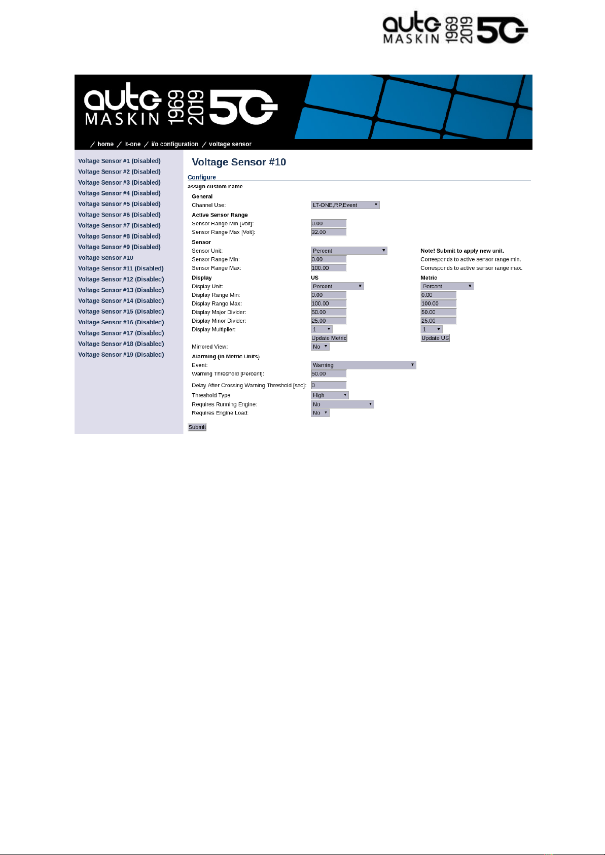
In this example, we are configuring the Voltage Sensor #10 as a warning channel with a
high threshold limit of 50 %. When the event threshold is met, a yellow event will be raised.
In the Configure section from the above image, consider the following:
■assign custom name: This is where the channel is given a descriptive text.
○ Choose a language, then type the channel description. Finally, click the
Submit button.
○ In the left margin, select the Voltage Sensor #10 item to return to the channel
configuration.
■General: Channel Use shall be set to LT-ONE,RP,Event
■ Active Sensor Range: The sensor range
■ Sensor:
○ Sensor Unit: Select the unit of the sensor
○ Sensor Range Min / Max: Select the minimum and maximum range of the
sensor
■ Display: This defines how the channel will be graphically represented
■ Alarming:
Page 20 (24)
This manual suits for next models
2
Table of contents
Other auto maskin Marine Equipment manuals

auto maskin
auto maskin 1006451 User manual

auto maskin
auto maskin Marine Watch S Series User manual

auto maskin
auto maskin Marine Pro 400 Series Instruction sheet

auto maskin
auto maskin Marine Pro DCU 410E User manual

auto maskin
auto maskin Marine Pro 400 Series User manual

auto maskin
auto maskin Marine Pro Series User manual

auto maskin
auto maskin Marine Pro 200 Series User manual

auto maskin
auto maskin Marine Pro 400 Series User manual

auto maskin
auto maskin Marine Pro 200E Series User manual

auto maskin
auto maskin Marine Pro 400 Series User manual


