DESCRIZIONE
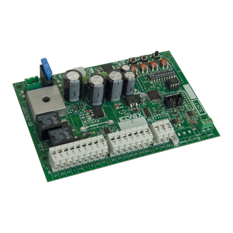
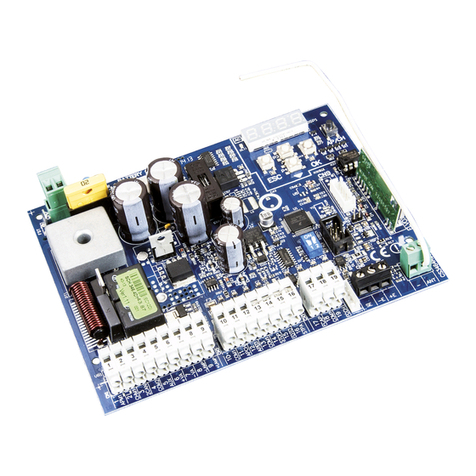
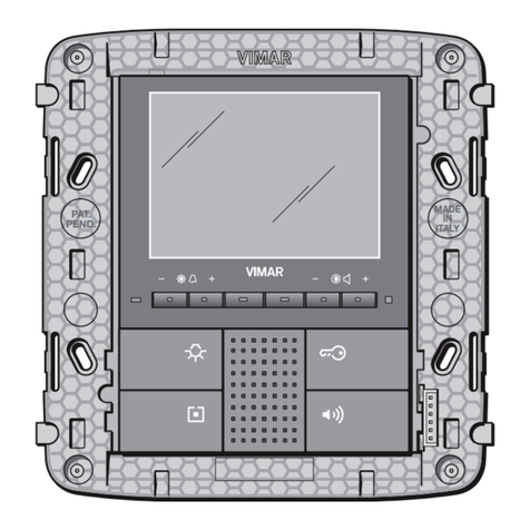
13C5, unità elettronica base per la composizione di un casellario postale
con 8 pulsanti di chiamata di tipo tradizionale.
Per l’espansione del numero di chiamate è necessaria l’installazione
dell’articolo 693P o dell’art. 693P/M.
La confezione comprende:
- Unità elettronica (art. 13C5)
- Morsettiera per il collegamento dell’unità elettronica all’impianto DUE
FILI PLUS
- Confezione di adesivi per il pannello audio video del casellario
- Viti per il fissaggio dell’unità elettronica e della morsettiera nel pannello
audio / video.
B2
B1
EXT+
EXT-
VLED
M
PA
CA
M
S+
S-
+12V
-L
SR
F2
F1
M
X
CN2 CN1
CN1) Connettore per unità elettronica.
CN2) Connettore per programmatore art. 950C
o interfaccia art. 692I/U o art. 692I.
B2) Bus 2 fili (montante).
B1) Bus 2 fili (montante).
EXT+) Alimentazione esterna (+ Art. 6923).
EXT-) Alimentazione esterna (- Art. 6923)
VLED)
Alimentazione LED per moduli supplemen-
tari.
X) Ingresso video (anima coassiale), per te-
lecamera esterna (solo con 2930)
M) Ingresso video (calza coassiale), per tele-
camera esterna (solo con 2930).
PA) Ingresso per sensore porta aperta (con
riferimento al morsetto M).
CA) Comando apriporta (con riferimento al
morsetto M).
M) Massa.
S+) Uscita serratura 12Vcc (+).
S-) Uscita serratura 12Vcc (-).
+12V) Uscita +12V (max 100 mA) con protezione
PTC.
-L) Pilotaggio telecamera esterna, uscita
open collector.
SR) Pilotaggio serratura tramite relè, uscita
open collector.
F2) Pilotaggio funzione F2 tramite relè, uscita
open collector.
F1) Pilotaggio funzione F1 tramite relè, uscita
open collector.
M) Massa.
)*
*L’unità elettronica fornisce un picco di corrente IT> 1A per 10ms
dopo il quale segue una corrente di mantenimento IM= 200mA per
tutta la durata del comando serratura (vedi tempo serratura).
A
B
C
A-B-C: Connettori modulo pulsanti supplementari Art. 693P/M.
I connettori A-B-C sono interscambiabili fra di loro
Per ottenere l’illuminazione dei cartellini portanome (scheda a LED art.
R264) è necessario eseguire un collegamento tra i morsetti +12V e V LED
della morsettiera in dotazione con l’unità elettronica art. 13C5
Fig. 1 - Morsettiera
DESCRIPTION
13C5, standard electronic panel for assembly of a post box with 8 con-
ventional pushbuttons. To expand the number of calls, installation of type
693P or type 693P/M is necessary.
The package includes:
- Electronic unit (type 13C5)
- Terminal block for connecting the electronic unit to the DUE FILI PLUS
system
- Stickers set to be applied on the audio-video panel of the post box.
- Screws for securing the electronic unit and terminal block inside the
audio-video panel.
B2
B1
EXT+
EXT-
VLED
M
PA
CA
M
S+
S-
+12V
-L
SR
F2
F1
M
X
CN2 CN1
CN1) Connector for electronic unit.
CN2) Connector for programmer Type 950C or
interface type 692I/U or tpe 692I.
B2) 2-wire bus (cable riser).
B1) 2-wire bus (cable riser).
EXT+) External power supply (+ Art. 6923).
EXT-) External power supply (- Art. 6923)
VLED)
LED power supply for additional modules.
X) Video input (coaxial core), for external
camera (only with 2930).
M) Video input (coaxial sheath) for external
camera (only with 2930).
PA) Input for door open sensor (with reference
to terminal M).
CA) Door open command (with reference to
terminal M).
M) Ground.
S+) 12Vdc lock output (+).
S-) 12Vdc lock output (-).
+12V) +12V output (max 100 mA) with PTC pro-
tection.
-L) External camera pilot, open collector
output.
SR) Lock pilot via relay, open collector output.
F2) F2 function pilot via relay, open collector
output.
F1) F1 function pilot via relay, open collector
output.
M) Ground.
)*
*The electronic unit supplies a current peak IT> 1A for 10ms, after that
an holding current IM= 200mA follows for the entire duration of the
lock command (see lock time).
A
B
C
A-B-C: Connectors for additional pushbutton module Type 693P/M
Connectors A-B-C are interchangeable
To get name-tag holder lighting (LED card type R264), it is necessary
to make a connection of electric cable between the +12V and V LED
terminals of the terminal block supplied with the electronic unit type 13C5.
Fig. 1 - Terminal block
CARATTERISTICHE TECNICHE
- Alimentazione attraverso i morsetti B1, B2.
- Alimentazione attraverso i morsetti Ext+, Ext- nei casi in cui c’è la ne-
cessità di alimentare l’unità elettronica tramite alimentatore supplemen-
tare.
- Uscita segnale video 16 dBm (con 2559)
- Assorbimento in Stand by 60 mA
- Assorbimento in comunicazione 260 mA
- Assorbimento in comunicazione e attivazione serratura 450 mA
- Tensione minima sui morsetti B1, B2 24 Vdc
- Temperatura di funzionamento: -10° C / +55° C.
TECHNICAL CHARACTERISTICS
- Power via terminals B1, B2
- Power via terminals Ext+, Ext- if the electronic unit needs to be powered
via an additional power supply.
- Video signal output 16 dBm (with 2559)
- Absorption in standby 60 mA
- Absorption in communication 260 mA
- Absorption in communication and lock activation 450 mA
- Minimum voltage on terminals B1, B2 24 Vdc
- Operating temperature: -10°C / +55°C.
NOTA: Per abilitare l’unità elettronica al funzionamento in “MODALITA’
ESTESA”, utilizzare l’interfaccia art. 692I/U collegata ad un PC con
installato il Software SaveProg/EVCom.
NOTE: To enable the electronic unit in “EXTENDED MODE”, use
interface art. 692I/U connected to a PC on which the SaveProg/EVCom
software has been installed.
The instruction manual is downloadable from the site www.
vimar.com
Il manuale istruzioni è scaricabile dal sito www.vimar.com
2
13C5
