REV. 5-7-14 Page 4
WARNING: Proper clearances from combustible materials must be maintained from all sides, top and bottom of this
appliance. Use the specications listed on page 3 for proper clearance to combustibles.
PREPARING A NON-COMBUSTIBLE STRUCTURE
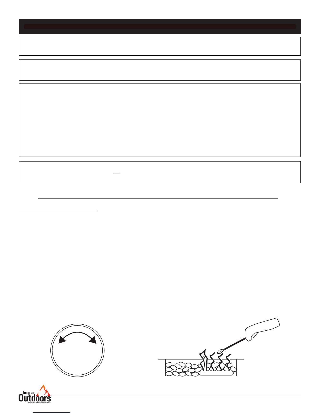
Install re pit on any level, outdoor non-combustible, at stable surface or a combustible oor according to the clearances
specied in this manual. NOTE: Do not place re pit directly on grass, dirt, or rocks this may prevent proper
ventilation (Fig. 3, pg. 5). Ensure proper water drainage is also incorporated into the re pit enclosure.
HARD PIPING TO FIRE PIT WITHOUT GAS PROXIMITY
NOTE: We recommend using 3/4” black iron pipe; however, please refer to the NFPA54 (National Fuel Gas Code) for
proper pipe sizing when exceeding 20-feet in length for re pits rated above 100,000 Btu’s.
1. Turn OFF gas supply system. NOTE: All gas connections (except for brass to brass) require the following. Clean pipe
threads using either a wire brush or steel wool. Apply pipe sealant to the ttings before making any connection.
BE CAREFUL! Ensure all gas connections are snug, but do not over tighten!
2. Extend the gas supply using minimum of ¾” black iron pipe or an approved exible gas line from existing house
supply. This can be accomplished by teeing off or tapping into a gas line connection. Install necessary pipe for the
distance required and then install a manual shut-off valve at the exterior house wall. If pipe is to pass through a foundation
or house wall, make sure to re-seal the area around the pipe with weather sealant.
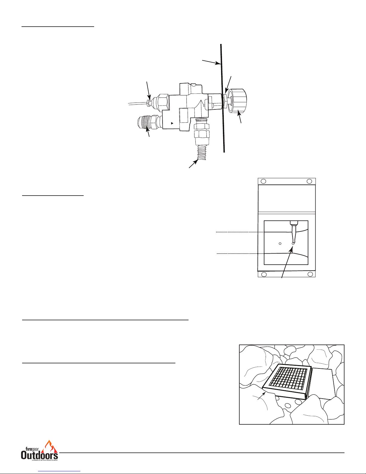
3. The primary gas shut-off (not supplied) will require a ½” Male ared tting to enable connection of the stainless steel
ex gas line supplied with the re pit (see gure 9 page 7).
IMPORTANT
Installation of Natural or LP gas should be done by a qualied installer, service agency or gas supplier.
The appliance and its manual shutoff valve must be disconnected from the gas supply piping system during any
pressure testing of the system at test pressure testing of the system at test pressures in excess of ½” psig (3.5kPa).
This appliance must be isolated from the gas supply piping system by closing its manual shutoff valve during any
pressure testing of the gas supply piping system at test pressures equal to or less than ½” psig (3.5kPa)
VENTILATION FOR NON-COMBUSTIBLE ENCLOSURE
Fire pits are subjected to many outdoor elements such as rain,
snow, wind, heat or cold. A minimum of 18 square inches of
cross ventilation (2 sides) is required to keep the
components in good working order. Use gure 3 as guide
to assist to incorporate proper ventilation.
Fire Pit
Enclousure
2”x3”
Fire Pit
Examples of Cross Ventilation
3 - 2”x3” Slots Per Side or
2- 1” x 9” Slots Per Side
Cross Flow Ventilation
(Min. 18 Sq. In. Per Side)
Figure 3. Cross Ventilation Example
TMS Burning Spur Fire pits