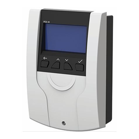
PAW FC3.10 Owner's manual

PAW GmbH & Co. KG
Böcklerstr. 11, 31789 Hameln - Germany
Phone: +49-5151-9856-0, Fax: +49-5151-9856-98
E-mail: [email protected], Web: www.paw.eu
2021/03 99E13331xx-mub-en - V07 1
Installation and Operation Instructions
Controller FC3.10
for DHW modules

1General Information
2 99E13331xx-mub-en - V07 2021/03
Item no. 99E13331xx-mub-en - Version V07 - Issued 2021/03
Translation of the original instructions
We reserve the right to make technical changes without notice!
Printed in Germany – Copyright by PAW GmbH & Co. KG
PAW GmbH & Co.KG
Böcklerstraße 11
31789 Hameln - Germany

1General Information
2021/03 99E13331xx-mub-en - V07 3
Contents
1General Information.........................................................................................................7
1.1 Scope of these instructions ..........................................................................................7
1.2 Designated use ............................................................................................................ 7
1.3 Target group ................................................................................................................ 7
2Safety instructions ...........................................................................................................8
3Mounting and installation [specialist] ................................................................................9
3.1 Installation of the controller........................................................................................... 9
3.2 Establishing the electrical connections ....................................................................... 11
4Product description and operation ..................................................................................13
4.1 View of the controller.................................................................................................. 13
4.2 Operating buttons / key combination .......................................................................... 13
4.3 Display ....................................................................................................................... 14
4.4 Symbols ..................................................................................................................... 14
5Commissioning [specialist].............................................................................................15
5.1 Language ................................................................................................................... 15
5.2 Controller mode.......................................................................................................... 15
5.3 Date ........................................................................................................................... 15
5.4 Time........................................................................................................................... 16
5.5 Automatic daylight saving time / standard time........................................................... 16
5.6 Scan Modbus ............................................................................................................. 16
5.7 Nominal temperature.................................................................................................. 16
5.8 Functions ................................................................................................................... 16
5.9 Finish with protocol .................................................................................................... 17
5.10 Finish without protocol................................................................................................ 17
6Menu settings................................................................................................................18
7Status ...........................................................................................................................21
7.1 Measured values........................................................................................................ 21

1General Information
4 99E13331xx-mub-en - V07 2021/03
7.2 Messages...................................................................................................................22
7.3 Service....................................................................................................................... 22
7.4 Controller ................................................................................................................... 22
8Hot water ......................................................................................................................23
9Functions ......................................................................................................................23
10 General settings ............................................................................................................24
10.1 Language ................................................................................................................... 24
10.2 Date ........................................................................................................................... 24
10.3 Time........................................................................................................................... 24
10.4 Synchronise date/time................................................................................................ 25
10.5 Auto daylight saving time ........................................................................................... 25
10.6 Commissioning* ......................................................................................................... 25
10.7 Software update ......................................................................................................... 25
10.8 Display ....................................................................................................................... 25
11 Internet module .............................................................................................................26
11.1 Registration................................................................................................................ 26
11.2 Set up the network ..................................................................................................... 26
11.3 Information ................................................................................................................. 26
12 USB..............................................................................................................................27
12.1 Eject memory ............................................................................................................. 27
12.2 Load settings.............................................................................................................. 27
12.3 Save settings.............................................................................................................. 27
12.4 Save alarms history.................................................................................................... 27
12.5 Save parameters history ............................................................................................ 27
12.6 Data logging interval................................................................................................... 28
12.7 Recording type ........................................................................................................... 28
12.8 Format drive............................................................................................................... 28
12.9 Properties................................................................................................................... 28
13 Auto / manual mode ......................................................................................................29

1General Information
2021/03 99E13331xx-mub-en - V07 5
14 User code .....................................................................................................................30
15 Advanced settings .........................................................................................................30
15.1 Min speed* ................................................................................................................. 30
16 Description of function ...................................................................................................31
16.1 Circulation .................................................................................................................. 31
16.2 Stratification (stratification of return) ........................................................................... 35
16.3 Modulating hot water temperature.............................................................................. 36
16.4 Comfort function......................................................................................................... 37
16.5 Disinfection ................................................................................................................ 38
16.6 Alarm relay................................................................................................................. 39
16.7 Parallel relay .............................................................................................................. 40
16.8 Hygienic flush/protection against blocking .................................................................. 41
16.9 Buffer storage* ........................................................................................................... 41
16.10 Reheating* ................................................................................................................. 42
17 Installation of the cascade controller...............................................................................42
17.1 Installation.................................................................................................................. 43
17.2 Initial commissioning of the cascade controller........................................................... 47
17.3 Extension of a single controller to a cascade network ................................................ 48
18 Menu settings cascade ..................................................................................................49
19 Submenu
Cascade
at the client......................................................................................50
19.1 Cascade switchover points......................................................................................... 50
19.2 Switchover point ON* ................................................................................................. 50
19.3 Switchover point OFF* ............................................................................................... 50
19.4 Switchover delay*....................................................................................................... 51
19.5 Duration of standby module* ...................................................................................... 51
19.6 Synchronise*.............................................................................................................. 51
19.7 Debug*....................................................................................................................... 51
19.8 Information*................................................................................................................ 51
20 Submenus at the server.................................................................................................52

1General Information
6 99E13331xx-mub-en - V07 2021/03
20.1 Status......................................................................................................................... 52
20.2 General settings ......................................................................................................... 53
20.3 USB ........................................................................................................................... 53
20.4 Automatic / manual mode........................................................................................... 53
20.5 Advanced settings* .................................................................................................... 53
21 Functions in the cascade network ..................................................................................53
21.1 Circulation .................................................................................................................. 54
21.2 Stratification of return ................................................................................................. 55
21.3 Comfort function......................................................................................................... 55
21.4 Thermal disinfection ................................................................................................... 55
21.5 Alarm relay................................................................................................................. 56
21.6 Parallel relay .............................................................................................................. 56
21.7 Hygienic flush / protection against blocking ................................................................ 56
21.8 Buffer tank.................................................................................................................. 56
21.9 Reheating...................................................................................................................56
22 Technical data...............................................................................................................57
23 Error correction .............................................................................................................58
23.1 Error messages.......................................................................................................... 58
23.2 Troubleshooting ......................................................................................................... 60
23.3 Checking the VFS 2-40 flow sensor ........................................................................... 63
23.4 Checking the FlowSonic flow sensor .......................................................................... 64
24 Disposal........................................................................................................................66
25 Exclusion of liability .......................................................................................................66
26 Legal guarantee ............................................................................................................67

1General Information
2021/03 99E13331xx-mub-en - V07 7
1General Information
1.1 Scope of these instructions
These instructions describe the function, installation and commissioning of the DHW controller
FC3.10. The chapters called [specialist] are intended for specialists only.
For further components external of the module, such as valves, please follow the instructions of
the respective manufacturer.
1.2 Designated use
The domestic hot water controller, subsequently referred to as the
controller
, is an
independently installed electronic temperature controller for on-surface installation. The
maintenance-free controller is exclusively intended for the controlling and monitoring of a PAW
domestic hot water module. Improper usage of the controller excludes any liability claims.
Only use PAW accessories with the controller.
The packaging materials are made of recyclable materials and can be disposed of with
recyclable materials.
This product complies with the relevant directives and is therefore labelled with the CE mark.
The Declaration of Conformity is available upon request, please contact the manufacturer.
1.3 Target group
The target audience of this manual are technical professionals who:
•have the knowledge of terminology and the skills necessary for setting up and
operating domestic hot water modules.
•have the necessary professional training, knowledge and experience as well
as the knowledge of the relevant regulations, in order to evaluate the following
work and to detect potential dangers:
– Installation of electrical devices
– Assembly and connection of data lines
– Assembly and connection of power supply lines.
Carefully read these instructions before installation and commissioning. Save
these instructions in the vicinity of the installation for future reference.

2Safety instructions
8 99E13331xx-mub-en - V07 2021/03
2Safety instructions
The installation and commissioning as well as the connection of electrical components require
technical knowledge commensurate with a recognised vocational qualification as a fitter for
plumbing, heating and air conditioning technology, or a profession requiring a comparable level
of knowledge [specialist].
The following must be observed during installation and commissioning:
•relevant local and national regulations
•accident prevention regulations of the professional association
•instructions and safety instructions mentioned in these instructions
CAUTION
Personal injury and damage to property!
The controller must only be used in domestic hot water modules.
The domestic hot water module can be damaged by improper operation of
the device. The device must not be connected to the power supply if:
the body is open or damaged.
cables are damaged.
This document is part of the product. Install and use the device only after having read
and understood this document. Please observe all safety instructions. Please contact
an additional expert if uncertainties occur.
The measures described in this document may only be carried out by qualified technical
professionals.
Factory labels and markings must never be modified, removed or rendered unreadable.
Observe the prescribed operating conditions. For more information, see the section
Technical
data.
This device is not intended for:
•Children
•Persons with restricted physical, sensory or mental capacities
•Persons without sufficient experience or knowledge unless they are instructed in the use
of the device, and initially supervised, by a person responsible for their safety.

3Mounting and installation [specialist]
2021/03 99E13331xx-mub-en - V07 9
3Mounting and installation [specialist]
3.1 Installation of the controller
NOTICE
The following section describes only the installation of the controller.
Follow the instructions of each respective manufacturer when installing external components
(valves etc.)
Do not put the controller into operation in case of any visible damage.
1. temperature sensors
S1-S4 (Pt1000)
2. flow sensors
(VFS/US)
3. outputs PWM
4. modbus (RS 485)
5. RS 232
6. outputs 230 V
7. supply
8. position of the jumper
9. fuse
WARNING
Risk of death by electrocution!
Disconnect the controller from the power supply before opening the
body.
Make sure that the power supply cannot be unintentionally switched on
when the body is open.

3Mounting and installation [specialist]
10 99E13331xx-mub-en - V07 2021/03
Inputs FriwaMini:
Terminal
Individual operation mode / Cascade operation mode
S1, ꞱFlow temperature, primary (T-VL)
S2, ꞱOptional: Storage tank temperature (T-SP), ext. circulation temperature,
ext. stratification temperature
S3, ꞱOptional: Storage tank temperature (T-SP), ext. circulation temperature,
ext. stratification temperature
S4, ꞱCold water temperature, secondary (T-CW)
VFS/US1 Domestic hot water temperature (T-DHW) and flow rate, secondary
Inputs FriwaMidi/Maxi/Mega:
Terminal
Individual operation mode / Cascade operation mode
S1, ꞱFlow temperature, primary (T-VL)
S2, ꞱDomestic hot water temperature, secondary (T-DHW)
S3, ꞱOptional: Storage tank temperature (T-SP), ext. circulation temperature,
ext. stratification temperature
S4, ꞱCold water temperature, secondary (T-CW)
VFS/US1 Flow rate, secondary
VFS/US2 (for Friwa Mega): flow rate, secondary
Outputs:
Terminal
Individual operation
Cascade operation mode
R1 Optional: alarm relay, error relay,
reheating, stratification
Cascade valve
R2 Optional: stratification, alarm
relay, error relay, reheating
Stratification
(Connection at server 1)
R3 Primary- / secondary pump Primary- / secondary pump
PWM 1 Primary pump Primary pump
PWM 2 Secondary pump (circulation) Secondary pump
(circulation at the client)

3Mounting and installation [specialist]
2021/03 99E13331xx-mub-en - V07 11
3.2 Establishing the electrical connections
WARNING
Risk to life and limb due to electric shock!
Make sure that the following conditions are met when performing the work
described in this section:
All cables leading to the controller must be disconnected from the power
supply and it must be ensured that they cannot be unintentionally
reconnected during installation.
The protective earth conductors (PE) from the mains cable and pump
and valve cables must be connected to the protective earth conductor
terminal block.
All cables must be laid so that persons cannot stand on them or trip over
them.
The cables must meet the requirements listed in the
Technical data
section.
The local power supply must match the specifications on the type plate
of the controller.
The power supply cable is to be connected to the mains power as
follows:
-using a plug connected to a wall mains socket or
-via an isolating mechanism allowing complete isolation in the case of
permanent wiring.
The power supply cable must be laid in conformance to all applicable
legal guidelines and regulations of the local electricity supplier.
ATTENTION
Danger of damage and malfunction!
Connect only components that do not overload the controller inputs and outputs; more
information is provided on the type plate and in the
Technical data
section.

3Mounting and installation [specialist]
12 99E13331xx-mub-en - V07 2021/03
NOTICE
Any connection polarity may be used for the 1 – 4 signal inputs and outputs.
Only type Pt1000 temperature sensors may be used.
Lay the sensor cables at least 100 mm away from any power supply cables.
Use shielded sensor cables when inductive sources are present, e.g. high-voltage
lines, radio transmitters, microwave devices.
ATTENTION
Danger of damage and malfunction!
When using a circulation pump, especially with the FriwaMega, the power consumption of the
pumps connected to the controller must absolutely be observed and it has to be checked
whether they are compatible with the controller. In some cases, the circulation pump directly
has to be supplied by the mains connection. The speed is controlled via the PWM signal.

4Product description and operation
2021/03 99E13331xx-mub-en - V07 13
4Product description and operation
4.1 View of the controller
4.2 Operating buttons / key combination
Button
Description
Back:
goes back to the next higher level or back to the system
overview
Upwards:
navigates upwards in the menu, increases adjustment
values
Downwards:
navigates downwards in the menu, decreases
adjustment values
Confirm:
opens the main menu, goes to the next lower level, confirms
set values, activates functions
Key combination
Description
Standby on
Back
and
confirm
- keep button pressed
Standby off
Back
- keep button pressed for 5 s
Factory settings
Confirm
- keep button pressed for 30 s
Software update
Upwards
and
downwards
- keep button pressed for 5 s (USB flash
drive with firmware version connected)
USB service
interface (below
the front panel)
Operating buttons
Display with
hydraulic scheme

4Product description and operation
14 99E13331xx-mub-en - V07 2021/03
4.3 Display
4.4 Symbols
Symbol
Description
Three-way valve with flow direction
Check box (activated/deactivated)
Disinfection active
Error message
Manual mode
Pump
Storage tank
Thermometer
Heat exchanger
Modulating hot water temperature active
Water withdrawal point
USB record active
Hot water
temperature
(T-DHW)
Flow temperature
(T-VL)
Flow rate (VFS V)
Speed of the primary
pump (PWM 1)
Cold water
temperature (T-CW)
Speed of the
circulation pump
(PWM 2)
Remaining time of
disinfection
Time with day of
the week

5Commissioning [specialist]
2021/03 99E13331xx-mub-en - V07 15
5Commissioning [specialist]
DANGER
Risk to life and limb due to electric shock!
Be sure to perform all the measures listed in the
Mounting and
installation
section before starting the first commissioning.
When the controller is connected for the first time, the message "Please carry out the first start-
up" is shown on the display.
After confirming with "Yes", the commissioning menu is displayed where you can successively
make the desired general settings.
5.1 Language
LANGUAGE
Deutsch (DE)
Polski (PL)
English (ENG)
Français (FR)
Sets the desired menu language.
5.2 Controller mode
CONTROLLER M O D E
Single controller
Client (ID1)
Server 1 (ID2)
Server 2 (ID3)
Sets the available type of controller.
The menu item
Single controller
should be selected if you
want to put into operation only one domestic hot water
module. If you connect multiple domestic hot water
modules (2 - 4 modules) hydraulically in parallel, these
controllers are called cascading.
The controllers are connected via a bus line with each other and are called
client
or
server
.
5.3 Date
SET DATE
17 – 03 – 2020
Day
Sets the current date.
First set the day, the month and finally the year.

5Commissioning [specialist]
16 99E13331xx-mub-en - V07 2021/03
5.4 Time
SET TIME
09 : 16
Hour
Sets the current time.
First set the hours, then the minutes.
5.5 Automatic daylight saving time / standard time
Activates/deactivates the automatic daylight saving time / standard time.
When the controller is delivered, this item is activated.
5.6 Scan Modbus
SCAN MODBUS
STATUS
Server 1
OK
Server 2
---
Server 3
---
IO-MODUL
---
MB3.10
---
The identification of the domestic hot water modules
which are operated in the cascade mode is made via the
menu item
Scan Modbus.
The dot marks which controller type is searched at the
moment.
5.7 Nominal temperature
NOMINAL TEMPERATURE
60 °C
60 °C
MIN : 35 MAX : 75
Sets the desired nominal temperature of the hot water.
5.8 Functions
Activates/deactivates the functions and further, corresponding settings.
When the domestic hot water module is delivered, as well as after a reset to factory settings
(see chapter 4.2), all functions are deactivated apart from
Over temperature switch off.
You will find detailed information on this in chapter 16.

5Commissioning [specialist]
2021/03 99E13331xx-mub-en - V07 17
5.9 Finish with protocol
Saves the commissioning with creating a protocol. For this, an external memory (USB flash
drive) must be connected to the service interface / USB port. This interface can only be
accessed after removal of the front panel, see chapter 4.1.
5.10 Finish without protocol
Completes the commissioning without a further saving on an external USB flash drive.
The settings made during the commissioning can be changed at any time in the corresponding
submenus.
After the commissioning is completed, the controller is ready for use.
Parameters
Meaning
Adjustment range
Factory setting
Language Selects the menu language German, Polish,
English, French,
Spanish, Italian
German
Controller mode Sets the type of controller Single controller,
client, server 1,
server 2, server 3,
IO-module,
deactivated
Single controller
Date Sets the date - -
Time Sets the time - -
Auto. Daylight
saving time /
standard time
Activates the automatic
change to daylight saving
time /standard time
Yes, No Yes
Scan Modbus Identifies the modules - -
Nominal
temperature
Sets the hot water nominal
temperature
35 ... 75 °C 60 °C
Functions Submenu of the functions - -
Finish with protocol Saves with protocol - -
Finish without
protocol
Saves without protocol - -

6Menu settings
18 99E13331xx-mub-en - V07 2021/03
6Menu settings
By pressing the operating button ( ), the menu of the controller FC3.10 opens.
The menu bar contains multiple submenus in which you can find or modify various settings.
The available menu items of the first three levels are shown as a menu tree and will be
explained in detail in the following chapters.

6Menu settings
2021/03 99E13331xx-mub-en - V07 19
Menu
Status
Measured values
Messages
Service
Controller
Hot water
D.H.W. set temperature
D.H.W. set temperature min*
D.H.W. set temperature max*
Functions
Circulation
Stratification of return
Modulating hot water temperature
Comfort function
Disinfection
Alarm relay
Parallel relay
Hygienic flush/protection
against blocking
Buffer storage*
Reheating*
General settings
Language
Date
Time
Synchronise date/time
Auto daylight saving time
Commissioning*
Software update
Display

6Menu settings
20 99E13331xx-mub-en - V07 2021/03
*Settings only visible with installer code (see chapter "User code").
Menu
Internet module
Registration
DHCP
IP address
Netmask
Gateway
DNS address
Information
USB
Eject memory
Load settings
Save settings
Save alarmshistory
Save parameters history
Data logging interval
Recording type
Format drive
Properties
Auto / Manual mode
Automatic mode
Sensor simulation
Relay 1
Relay 2
Relay 3
PWM 1
PWM 2
User code
Advanced settings* Min speed*
Other manuals for FC3.10
2
Table of contents
Other PAW Controllers manuals
Popular Controllers manuals by other brands

Minolta
Minolta IC-205 installation manual

Compit
Compit SOLARCOMP 951 Installation and operating instructions

Savant
Savant SmartControl 25 Quick reference guide

Mitsubishi
Mitsubishi MELSEC FX3U-4DA installation manual

National Instruments
National Instruments sbRIO-9637 user manual

Altronix
Altronix T2RM7CK1 installation guide