First Sales UVPC-12 User manual
First Sales, LLC
12630 US Highway 33 N
Churubusco, IN 46723
Phone (260) 693-1972 Fax (260) 693-0602
UVPC-12 and UVPC-20 Instructions 190726.docx
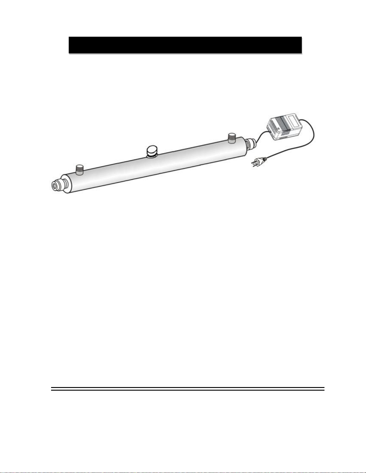
ULTRA VIOLET LIGHT
WATER STERILIZER
Please read these instructions completely before installing this unit.
UVPC-12 and UVPC-20

1
Never plug in UVlamp when itis outside the stainless steel chamber.
1. Water mayneed to be treated prior to entering the sterilizer. Water must be free of color and turbidity.
Turbidityand color will shield bacteria from the UV rays. A 5 micron sediment cartridge filter is
recommended to precede the UV. Water hardness should be 5 grains per gallon or less and the iron
concentration below0.3 ppm. Ideally, it should be soft and iron free.
2. All water treatment equipment (except reverse osmosis systems) should be installed before the
sterilizer.
3. A non-switched, 115 volt GFI protected electrical outlet is needed near the unit.
4. It is recommended that the unit be installed horizontally with adequate room on one side to remove the
quartz sleeve and bulb (approximately 37”).
5. Install only in an area that will maintain an ambient temperature between 36°F and 104°F.
6. Maximum operating pressure is 100 psi.
7. Connect to plumbing system while complying to all state and local regulations.
ITEM #
PART #
DESCRIPTION
1
UVPC-PG135
Water Proof Cord Strain Relief
2
UVPC-A02
Aluminum Nut
3
UVPC-4P80
Lamp Socket and Wire
4
UVPC-LAMP
Germicidal Lamp, 12 gpm, 9,000 hour
UVPC-LAMP-20
Germicidal Lamp, 20 gpm, 9,000 hour
5
UVPC-OR
O-Ring
6
UVPC-QS
QuartzSleeve
7
UVPC-ST635890
Stainless Steel Chamber, UVPC-12
UVPC-B6
Stainless Steel Chamber, UVPC-20
8
UVPC-1002
Mounting Clip for UVPC-12
UVPC-CLIP-20
Mounting Clip for UVPC-20
9
UVPC-BALL
Ballast, 115v, 12 gpm unit
UVPC-BALL-20
Ballast, 115v, 20 gpm unit
10
UVPC-GLO PLUG
UV Lamp indicator (Glow Plug)
Not
Shown
CV7A106D-12
External Flow Control, UVPC-12
CV7A106D
External Flow Control, UVPC-20
Pre-installation Instructions
Components
FIGURE 1

2
WARNING: NEVER PLUG IN UV LAMP WHEN IT IS OUTSIDE THE STAINLESS STEEL
CHAMBER. NEVER LOOK DIRECTLY AT ILLUMINATED UV LAMP
CAUTION: QUARTZ SLEEVE AND LAMP ARE EXTREMELY FRAGILE AND EASILY
DAMAGED…BE VERY CAREFUL WHEN HANDLING, INSTALLING AND REPLACING
THE SLEEVE AND LAMP. ALWAYS REPLACE THE QUARTZ SLEEVE WHEN
REPLACING THE LAMP.
1. Using mounting clips provided, mount the stainless steel chamber (Item 7) inthe desired
location. It isrecommended that the chamber be mounted horizontally to prevent dropping
the quartz sleeve and UV lamp during assembly. Ensure there is a minimum of 37” on one
side of the stainless steel chamber for installation and future replacement of the quartz
sleeve and UV lamp.
2. Install the flow control (12 gpm, UVPC-12 or 20 gpm, UVPC-20) on the connection that you
have designated asthe inlet of the unit. The unit itself is not directional regarding flow.
3. Connect inlet (with flow control) and outlet of the stainless steel chamber to the plumbing.
4. Avoid touching the sides ofthequartz sleeve and lamp. Handle only the ends. Gloves are
recommended to prevent getting oil from your hands on thequartz sleeve and UV lamp.
5. Remove aluminum nuts from both ends of the stainless steel chamber (Item 2).
6. Carefully insert the quartz sleeve (Item 6) into one end of the stainless steel chamber (Item
7) so that it exits the other end. Make sure equal lengths of quarts sleeve protrude from
each end.
7. Place an o-ring (item 5) on each end of the quartz sleeve where it enters the stainless steel
chamber.
8. Replace the aluminum nuts (item 2) on each end of the chamber. The nut without the plastic
end cover is for the end with the electrical cord. The nuts should be only hand tight.
9. Carefully slide the lamp through aluminum nut on one end of the chamber.
10. Ensure the power cord is NOT plugged in and connect the lamp to the lamp socket on the
wiring harness.
11. Screw the water proof cord strain relief (Item 1) into the aluminum nut.
12. Turn on water supply and check for leaks. Repair if necessary.
13. Plug the ballast (Item 9) into GFI (ground fault interrupt) protected electrical outlet.
14. Run water through the unit for 5 minutes prior touse.
15. If your unit has a maintenance timing device, attach the timer to the chamber. Strap and
screws are provided. Push the reset buttonto start the timer. The timer indicates when
lamp and quartzsleeve replacement is required.
If the plumbing system has been previously exposed to water that is known to have
bacterial contamination, the entire plumbing system will require disinfection once the
UV light is installed and in operation.
Installation

3
Replace the quartz sleeve and germicidal lamp annually.
1. Disconnect electrical power.
2. Turn off water supply and relieve pressurefrom system.
3. Unscrew power cord strain relief and slide the lamp out to disconnect the wiring.
4. Carefully remove lamp from chamber.
5. Unscrew both aluminum nuts and carefully remove the quartz sleeve. Retain the existing
O-rings for re-use or replace with new O-rings (item 5).
6. See installation procedure to install new quartz sleeve and lamp.
7. If timing device is used, press and hold buttonto reset timer.
Dimensions
UVPC-12
UVPC-20
(A) Distance Between Inlet and Outlet
31.5”
31.5”
(B) Chamber Diameter
2.5”
4.8”
(C) Total Height
4.3”
5.6”
(D) Overall Length
37”
38”
Maximum Flow Rate
12 GPM
20 GPM
Minimum UV Dose @ maximum flow rate
(at end of recommended bulb life)
16+ mJ/cm2
30+ mJ/cm2
UVWavelength 254 nanometers (nm)
UV Lamp Life 9,000 hours (1 year)
FeedWater Quality
Hardness <5 gpg
Iron <0.3 ppm
Manganese <0.05 ppm
Turbidity <5 NTU
Color None
Maintenance
Specifications

4
This UV system is guaranteed against any manufacturing defects that are due to faulty material
or workmanship during the warranty period. This warranty does not include damage to the
product resulting from accident, neglect, misuse, misapplication, alteration, installation or
operation contrary to printed instructions, or damage caused by freezing, fire, flood, or Acts of
God. For a period of two years from the original date of installation, or 30 months from
manufacture, whichever occurs first, we will repair or replace, at our discretion, any part found to
be defective. Purchaser is responsible for any shipping cost to our facility and any local labor
charges.
Stainless Steel Chamber
Aluminum Nuts
Ballast
Lamp Socket and Lead Wire
Strain Relief Fitting
GENERAL CONDITIONS –Should a defect or malfunction occur, contact the dealer that you
purchased the product from. If you are unable to contact the dealer, contact First Sales, LLC. @
(260)693-1972. We will require a full description of the problem, model number, date of
purchase, and selling dealer’s business name and address.
We assume no warranty liability in connection with this UV system other than specified herein.
This warranty is in lieu of all other warranties, expressed or implied, including warranties of
fitness for a particular purpose. We do not authorize any person or representative to assume for
us any other obligations on the sale of this UV system.
Two Year Limited Warranty
This manual suits for next models
1
Table of contents


