Hermle Z 307 User manual

HERMLE Z 307
User Manual


CONTENTS
© Hermle Labortechnik GmbH Z307_V1.22_eng I
1. PRODUCT DESCRIPTION ..........................................................................................................1
1.1 Safety Instructions..............................................................................................................................................................1
1.2 Intended Purpose................................................................................................................................................................1
1.3 Brief Description..................................................................................................................................................................1
1.4 Delivery Package.................................................................................................................................................................1
1.5 Installation of the Centrifuge............................................................................................................................................2
1.5.1 Unpacking the Centrifuge................................................................................................................................................2
1.5.2 Space Requirements........................................................................................................................................................2
1.5.3 Installation..........................................................................................................................................................................2
1.6 Signs and Indications of the Centrifuge.......................................................................................................................3
1.6.1 General...............................................................................................................................................................................3
1.6.2 Product Nameplate (Example)........................................................................................................................................3
1.6.3 Warning and Information Signs......................................................................................................................................4
1.6.4 Danger, Precautions and Warranty................................................................................................................................4
1.6.5 Following Rules Must Strictly be Adhered To:.............................................................................................................5
1.6.6 Warranty.............................................................................................................................................................................5
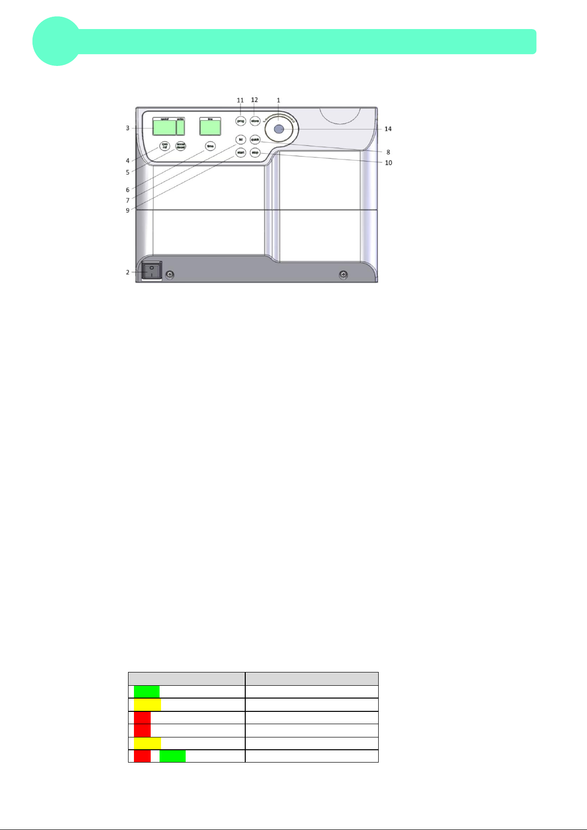
1.7 Operating and Display Elements....................................................................................................................................6
1.7.1 LED light............................................................................................................................................................................6
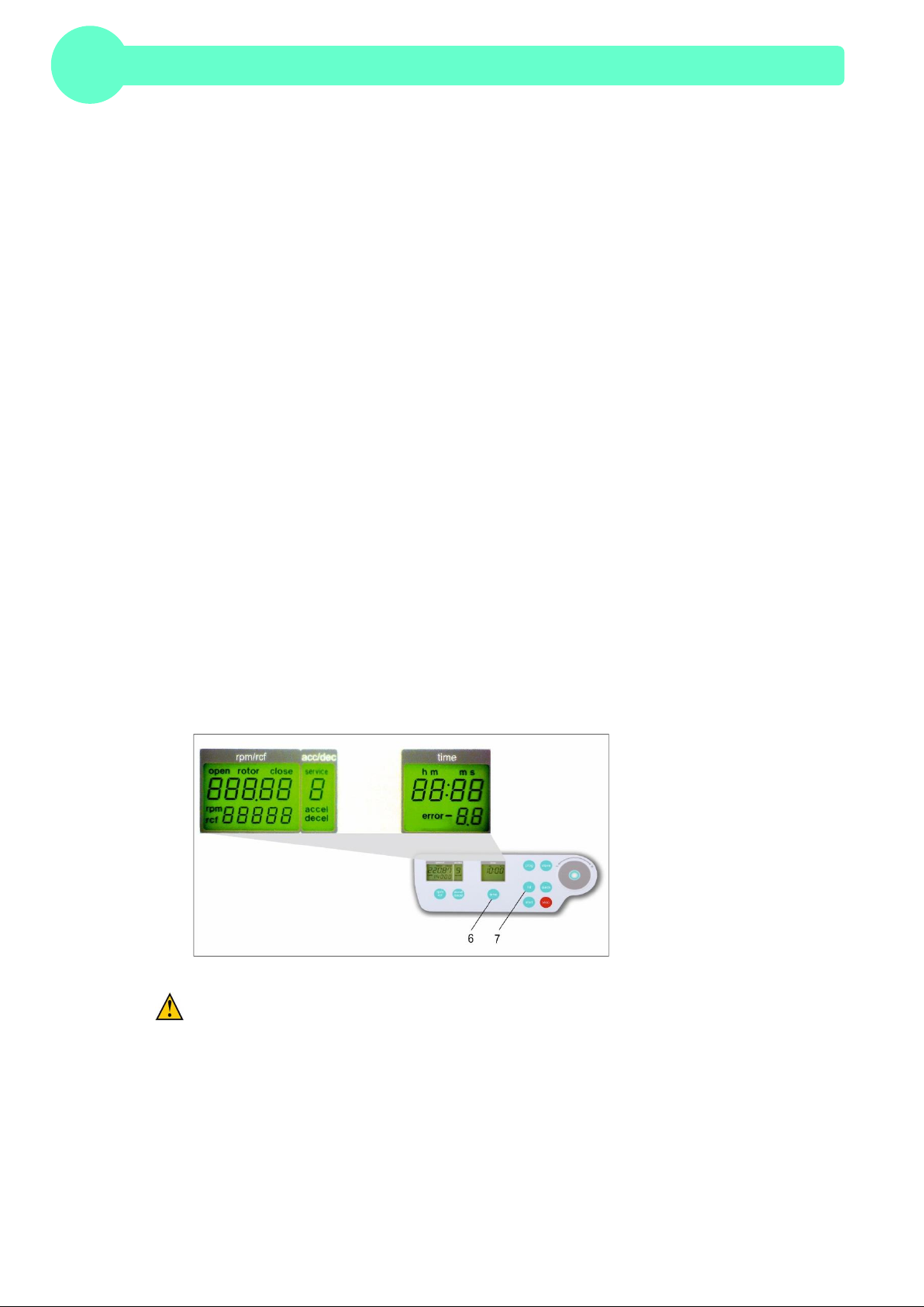
1.7.2 LCD-Display.......................................................................................................................................................................7
1.8 Basic Adjustments..............................................................................................................................................................8
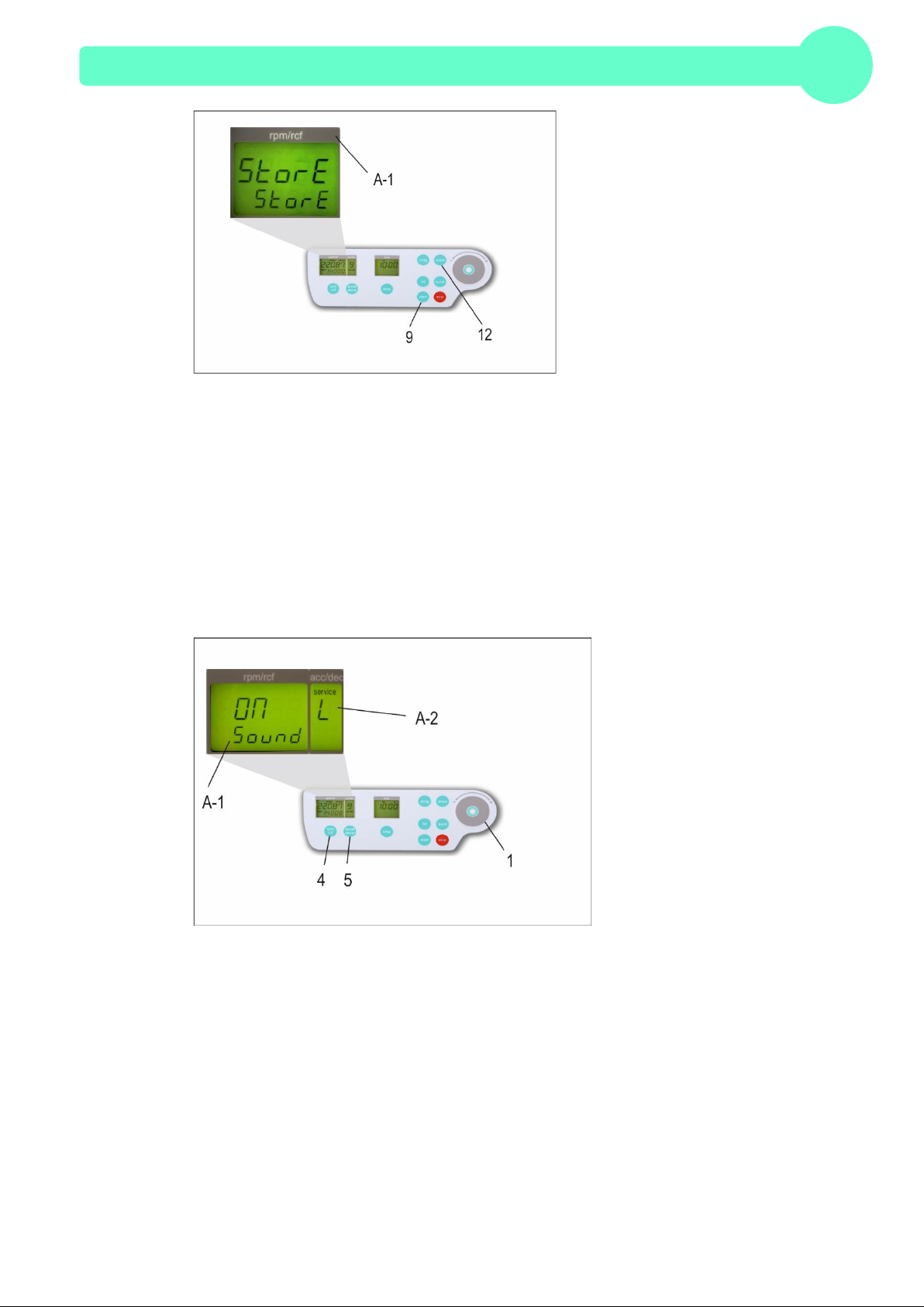
1.8.1 Access to the Mode: "Standard settings"......................................................................................................................8
1.8.2 Sound Signal Turn On / Off.............................................................................................................................................9
1.8.3 Volume Pre-Selection of Sound Signal.........................................................................................................................9
1.8.4 Song Selection - End of Run........................................................................................................................................ 10
1.8.5 Keyboard Sound Turn On / Off....................................................................................................................................10
1.8.6 Setting of the standby turn-off time............................................................................................................................. 11
1.8.7 Retrieving Operating Data............................................................................................................................................12
2. OPERATION............................................................................................................................... 13
2.1 Mounting and Loading the Angle Rotor..................................................................................................................... 13
2.1.1 Installation of Rotors......................................................................................................................................................13
2.1.2 Loading Angle Rotors....................................................................................................................................................13
2.1.3 Loading Swing Out Rotors............................................................................................................................................ 14
2.1.4 Loading and Overloading of Rotors............................................................................................................................ 15
2.1.5 Removing the Rotor....................................................................................................................................................... 15
2.2 Lid......................................................................................................................................................................................... 16
2.2.1 Lid Release..................................................................................................................................................................... 16
2.2.2 Lid Lock........................................................................................................................................................................... 16
2.3 Pre-Selection..................................................................................................................................................................... 17
2.3.1 Pre-Selection of Speed / RCF-Value.......................................................................................................................... 17
2.3.2 Pre-Selection of Running Time....................................................................................................................................17
2.3.3 Pre-Selection of Brake Intensity and Acceleration..................................................................................................18
2.4 Radius Correction ............................................................................................................................................................ 19
2.5 Program............................................................................................................................................................................... 19

CONTENTS
II Z307_V1.22_eng © Hermle Labortechnik GmbH
2.5.1 Storage of Programs..................................................................................................................................................... 19
2.5.2 Recall of Stored Programs...........................................................................................................................................20
2.5.3 Leaving Program Mode.................................................................................................................................................20
2.6 Starting and Stopping the Centrifuge......................................................................................................................... 21
2.6.1 Starting the Centrifuge.................................................................................................................................................. 21
2.6.2 The "STOP" Key............................................................................................................................................................. 21
2.7 Imbalance Detection........................................................................................................................................................ 22
2.8 Timer Function.................................................................................................................................................................. 22
3. Maintenance.............................................................................................................................. 24
3.1 Maintenance and Cleaning ............................................................................................................................................ 24
3.1.1 General Care:.................................................................................................................................................................24
3.1.2 Cleaning and Disinfecting of the Unit ......................................................................................................................... 25
3.1.3 Cleaning and Disinfecting of the Rotor....................................................................................................................... 25
3.1.4 Disinfection of Aluminum Rotors.................................................................................................................................25
3.1.5 Disinfection of PP-Rotors.............................................................................................................................................. 25
3.1.6 Glass Breakage.............................................................................................................................................................. 26
3.2 Lifetime of Rotors, Round and Rectangular Buckets, Accessories................................................................... 26
4. Trouble Shooting...................................................................................................................... 27
4.1 Error Messages: Problem / Solution........................................................................................................................... 27
4.2 Survey of Possible Error Messages and Solutions ................................................................................................ 27
4.2.1 Lid Release during Power Failure (Emergency Lid Release)................................................................................. 27
4.2.2 Description of the Error Message System................................................................................................................. 28
4.2.3 Procedure while error 14.............................................................................................................................................. 28
4.2.4 Procedure while error 38.............................................................................................................................................. 29
5. Receipt of Centrifuges for Repair ......................................................................................... 30
6. TRANSPORT, STORAGE AND DISPOSAL........................................................................... 31
6.1 Transport............................................................................................................................................................................ 31
6.2 Storage................................................................................................................................................................................ 31
6.3 Disposal.............................................................................................................................................................................. 31
7. APPENDIX......................................................................................................................................I
EC - Conformity Declaration.....................................................................................................................................................II
Table 1: Technical Data............................................................................................................................................................III
Table 2: Abbreviations............................................................................................................................................................. IV
Table 3: Permissible Net Weight............................................................................................................................................ IV
Table 4: Max. Speed and RCF-Values for Permissible Rotors.......................................................................................... V
Table 5: Acceleration and Deceleration Times..................................................................................................................... V
Table 6: Error Messages......................................................................................................................................................... VI
Table 7: Radius Correction.................................................................................................................................................... VII
Table 7(Part 2): Radius Correction...................................................................................................................................... VIII
Redemption Form / Decontamination Certificate................................................................................................................ IX

CONTENTS
© Hermle Labortechnik GmbH Z307_V1.22_eng III


PRODUCT DESCRIPTION
© Hermle Labortechnik GmbH Z307_V1.22_eng 1
1. PRODUCT DESCRIPTION
1.1 Safety Instructions
This symbol indicates safety instructions and points of potential dangerous situations. Before using
the centrifuge for the first time, please read the operating manual.
Failure to follow these instructions can result in personal injury and/or propertydamage.
Intended use includes:the observation of all instructions, in the instruction manual, and administering
inspection and maintenance.
1.2 Intended Purpose
This Hermle centrifuge was designed only for the separation of materials or mixtures with different
densities,specifically for the preparation and processing ofsamples,from the human body,in context
of an in-vitro-diagnostic use, to allow the use of in-vitro-diagnostic in accordance to its' intended
purpose. The designated device and its' accessories listed, in the technical documentation, are in
compliance with the Regulation (EU) 2017/746 of the European Parliament and of the Council of 5
April 2017 on in-vitro-diagnostic medical devices.
Hermle Centrifuges are intended exclusivelyfor indoor use and for the use of qualified personnel.
Only Hermle original rotors and accessories should be used.Any other use or intended use is strictly
prohibited.For any resulting damage,the company,Hermle Labortechnik,is not liable.
1.3 Brief Description
The unittype Z 307, is a non-refrigerated universal centrifuge,which we offer in two voltage variations
230Vor 120V.
The centrifuge can be used with swing-outrotors and angle rotors.
All parameters are accessible via buttons,and selected with a control field. All pre-selected and current
valueswill be shown,permanently,on the LCD-Display.
The centrifuge is powered by a Maintenance-Free Induction Motor.
Detailed technical data are in “Table 1: Technical Data" (see APPENDIX P.III).
1.4 Delivery Package
•1 Centrifuge Z 307
•1 Operating Manual Z 307
•1 Rotor Key
•1 Power Cord
Rotor(s) / Accessories will be packaged separately.

PRODUCT DESCRIPTION
2Z307_V1.22_eng © Hermle Labortechnik GmbH
1.5 Installation of the Centrifuge
1.5.1 Unpacking the Centrifuge
Model Z 307 is supplied in a carton. Remove the strap retainer, open the carton, and remove the
padding. Lift the centrifuge on both sides (see Figure 1) with an appropriate number of helpers and
place it on the laboratorytable.
Attention! Do not lift the centrifuge from under the lid or bythe front panel!
Figure 1
The instruction manual must be kept with the centrifuge, at all times!
1.5.2 Space Requirements
The centrifuge should be installed on an even, solid surface, if possible on a laboratorycabinet/ table
or some other solid vibration free surface.
During centrifugation, the centrifuge must be placed in a way, that there is a minimum space of
30 cm/11.81in on eachside of the unit, according to EN 61010-2-020 standards.
Do not place the centrifuge next to a window or a heater where itcould be disposed to excessive heat,
as the performanceof the unit is based on an ambienttemperatureof 23°C/73.4°F.
1.5.3 Installation
Follow These Steps:
•Check whether the power supply corresponds with the one specified on the manufacturer's rating
label, mounted on the rear panel.
•The power connection for the centrifuge requires a separate one-site protection,with 16 A (Type K)
•In case of emergency,there must be an emergencyswitch off installed outside of the room, in order
to disconnectthe powersupply from the unit.
•Connectthe centrifuge, with the mains.
(The socket for the power cord must be easy to reach, respectivelyeasyto disconnect).
•Switch on, by using the mains power switch (I).
•Open the lid, by using the button LID.
• Removethe transport securing device of the motor.

PRODUCT DESCRIPTION
© Hermle Labortechnik GmbH Z307_V1.22_eng 3
1.6 Signs and Indications of the Centrifuge
1.6.1 General
Direction of Rotation –clockwise rotation for the rotor drive
Reference for Loading Rotors
1.6.2 Product Nameplate (Example)
CompanyAddress:
Hermle Labortechnik GmbH, Siemensstr. 25, D-78564 Wehingen
In-Vitro-Diagnostic Medical Device
TYPE:
Type Designation of the Product
REF:
Order No. of the Product
SN:
Serial No. of the Product
Manufacturer
Date of Manufacture
MAX. Drehzahl:
Max. Speed Allowed ofthe Unit
KIN. EN.:
Max. Kinetic Energy with Corresponding Rotor
U/I/f:
Allowable Voltage / Max. Current / Frequency
P:
Electrical Input Power
Operating Manual Indication
Labeling,StandardsandGuidelines
RoHSConformity
UK-ConformityAssessed

PRODUCT DESCRIPTION
4Z307_V1.22_eng © Hermle Labortechnik GmbH
Instructions for Disposal, (see Chapter 6.3, P. 31)
1.6.3 Warning and Information Signs
Four carriers must be used at all times on four places swing out
rotors or damage will occur to the centrifuge. Such damage will
not be covered under the product warranty
Attention! Check the fastening of the rotor nut before each run
Take off mains plug before opening the housing or the emergency
release
Power Input
Biohazard Warning
1.6.4 Danger,Precautions andWarranty
This device may only be operatedby a trained professional.Carefully, read the operating
manualand be familiar with the functions of the device.
To protect people and the environment,the following precautions must be taken:
•During centrifugation, the presence of people and the arrangement of hazardous materials is
strictly prohibited, within 30 cm/12 in around the centrifuge, according to the regulations of
EN 61010-2-020.
•The HERMLE Z 307, is "non-explosion proof" and must not be operated in explosion-
endangered areas or locations. Centrifugation of flammable, explosive, radioactive, or such
substances, which chemically react with high energy, is strictly prohibited. If used in such
environment,this is at the users own expense.
•Never spin toxic or pathogenicmaterial withoutadequate safety precautions,i.e.centrifugation
of buckets / tubes with or without defective hermetic sealing,is strictly prohibited. The user is
obliged to perform appropriate disinfection procedures, in case dangerous substances have
contaminated the centrifuge and/or its' accessories.When centrifuging infectious substances,
alwayspay attention to the General LaboratoryPrecautions. If necessary, contact your safety
officer!
•It is prohibited to run the centrifuge, with rotors not manufactured for this unit.
•Under no circumstances open the lid of the centrifuge, while the rotor is still running or rotating
with a speed of > 2m/s

PRODUCT DESCRIPTION
© Hermle Labortechnik GmbH Z307_V1.22_eng 5
1.6.5 Following Rules Must Strictly be Adhered To:
•Do not operate the centrifuge if not installed correctly.
•Do not operate the centrifuge when dismounted (e.g. without housing).
•Do not run the centrifuge, if mechanical or electrical assembly groups have been tampered
with, by unauthorized personnel.
•Do not use accessories such as rotors and buckets, that are not approved by HERMLE
Labortechnik GmbH,exceptcommercially available centrifuge tubes,made of glass or plastic.
•Do not spin extremely corrosive substances, as they may cause material damages and impair
mechanical resistance.
•Do not operate the centrifuge with rotors or buckets, that show any signs of corrosion or
mechanical damage.
The manufactureris responsible for safety and reliability, ofthe centrifuge, only if:
•The unit is operated in accordance to this instruction manual.
•Modifications, repairs or other adjustments are performed by HERMLE-authorized personnel
and the electrical installation of the related location corresponds to the IEC-regulations.
1.6.6 Warranty
The centrifuge hasbeen subjected to thorough testing and quality control. In the unlikelycase of any
manufacturing faults occurring,the centrifuge and rotors are covered by warranty, for a period of two
years,from date of delivery.Thiswarranty becomes invalid in anycase of mishandling,damage and/or
negligence and further in any case of usage of inappropriate spare parts and / or accessories or
unauthorized modification ofthe unit.
Technical modification rights are reserved, by the manufacturer, in regards to technical
improvement!

PRODUCT DESCRIPTION
6Z307_V1.22_eng © Hermle Labortechnik GmbH
1.7 Operating and Display Elements
Figure 2
1controlfiled Run Parameters
20-I Power Switch
3LCD Control Panel Display
4rpm/rcf Speed/g-force
5 accel/decel Acceleration / Deceleration Intensity
6time Centrifugation Time
7 lid Lid Release
8quick Short Running
9start Start Centrifugation
10 stop Stop Centrifugation
11 prog Retrieving Programs
12 store ProgramStore
13 --
12 LED light Showsthe status of the centrifuge
1.7.1 LED light
The LED light indicates the current operation state of the centrifuge. The following table shows all
operating states.
Color of LED light
Operating state
Green
Run complete, lid is closed
Yellow
Lid opened,no sleep mode
Red flashing fast
Error message
Red flashing slow
Centrifuge runs
Yellow flashing slow
Sleep mode
Red –Green flashing slow
Standard settings menu

PRODUCT DESCRIPTION
© Hermle Labortechnik GmbH Z307_V1.22_eng 7
1.7.2 LCD-Display
The following picture shows the individual elements ofthe LCD-display.
Figure 3
DisplayFields:
A-1 DisplayField –"rpm/rcf"
A-2 DisplayField –"acc/dec"
A-3 DisplayField –"time"
Messages/Logos of the Display Fields:
M1 "close" M8 "decel"
M2 "open" M9 "radius"
M3 "rotor" M10 "program"
M4 Rotor-No. M11 "error"
M5 "rpm" M12 "service"
M6 "rcf" M13 h m s
M7 "accel"
Indication:
After switching on the centrifuge, the display, "rpm/rcf"(A-1) shows the loading status, the current
software version and finally the model type (e.g. Z 36 HK).
Figure 4

PRODUCT DESCRIPTION
8Z307_V1.22_eng © Hermle Labortechnik GmbH
1.8 Basic Adjustments
1.8.1 Access to the Mode: "Standard settings"
At commissioning ofthe centrifuge, you have the optionsto make the following basicchanges:
-Acoustic Signal Turn on / off
-Volume Pre-Selection of Sound Signal
-Song Selection of Sound Signal "end of run"
-Keyboard Sound Turn on / off
-Setting of the standby turn-off time
The following operating data can be retrieved in this menu:
-Number of starts
-Operating hours of centrifuge
-Operating hours of motor
-Software version centrifuge
-Software version frequencyconverter
-Error list
-Function of the imbalance sensor
-Operation of keyboard
-Hardware version
-Serial number of the control board
-Number of rotor starts of the mounted rotor
-Number of operating hours of the mounted rotor
-Update touch control panel (only for service engineers)
Open the centrifuge lid and shut off the main switch. Now switch on again the main switch. For
approximately 3 seconds the software version and the model type will be shown in the display (see
Figure 4). Press during this time the keys “time“ (6) and “lid“ (7) simultaneously.Asa result, a display
test is administeredfor approx. 3 seconds. All possible indications will appear at the same time (see
Figure 5). The LED lightis flashing alternately with green and red color.
Figure 5
Attention:
-The normal program mode can be changed back again by switching offthe centrifuge,for a short
period!
-All changed settings must be confirmed by the key “store” (12) or “start” (9). A confirmation
screen will appear with the word, “store”, in the display “rpm/rcf” (A-1), - Only then the pre-
selections are valid (see Figure 6).

PRODUCT DESCRIPTION
© Hermle Labortechnik GmbH Z307_V1.22_eng 9
Figure 6
1.8.2 Sound Signal Turn On / Off
Proceed as illustrated,underpoint 1.8.1, to enter this programmode,press the key; "accel/decel"(5).
In the display,"accel/decel"(A-2) flashesthe word, "service". Selectthe letter, "L" withthe control field
(1). As a result,appearing in the display "rpm/rcf" (4), are the words,"On Sound". By pressing the key,
"rpm/rcf" (4), the word "On" flashes, and the sound can be switched off withthe control field (1), (see
Figure 7).
After the settings have been stored by user, the normal program mode can be changed back again by
switching off the centrifuge,for a short period.
Figure 7
1.8.3 Volume Pre-Selection of Sound Signal
Proceed as illustrated,under point 1.8.1, to enter this programmode, pressthe key "accel/decel"(5).
In the display, "accel/decel" (A-2), flashes the word, "service". Select the letter, "U" with the control
field (1). As a result, appearing in the display, "rpm/rcf" (A-1), are the words, "Vol=0- 9/Sound". By
pressing the key, "rpm/rcf" (4), the desired volume can be adjusted between 0 (low) and 9 (loud),with
the control field (1), (see Figure 8).
After the settings have been stored by user, the normal programmode can be changed backagain by
switching off the centrifuge,for a short period.
1
7

PRODUCT DESCRIPTION
10 Z307_V1.22_eng © Hermle Labortechnik GmbH
Figure 8
1.8.4 Song Selection - End of Run
Proceed as illustrated,underpoint 1.8.1, to enter this programmode,press the key, "accel/decel"(5).
In the display, "accel/decel" (A-2) flashes the word, "service". Select the letter, "G" with the control
field (1). Asa result, appearing in the display,"rpm/rcf" (A-1), the word " SonGo/Sound".Afterpressing
the key „rpm/rcf“ (4), select a song with the control field (1), (see Figure 9).
After the settings have been stored by user, the normal programmode can be changed back again by
switching off the centrifuge,for a short period.
Figure 9
1.8.5 Keyboard Sound Turn On / Off
Proceed as illustrated,underpoint 1.8.1, to enter this programmode,press the key, "accel/decel"(5).
In the display;"accel/decel"(A-2) flashesthe word, "service". Selectthe letter, "b" withthe control field
(1). As a result, appearing in the display, "rpm/rcf" (A-1), the word "ON/BEEP". By pressing the key,
"rpm/rcf" (4), the keyboard sound (On) or (Off) can be turned on, with the control field (1), (see Figure
10).
After the settings have been stored by user, the normal programmode can be changed back again by
switching off the centrifuge,for a short period.
9
8

PRODUCT DESCRIPTION
© Hermle Labortechnik GmbH Z307_V1.22_eng 11
Figure 10
1.8.6 Setting of the standby turn-off time
After not using the centrifuge for 5 minutes, the centrifuge automaticallyfalls into the standby mode.
The display is switching off and the LED lightis flashing slowlywith yellow color.By pressing any key,
the centrifuge will be reactivated. The sleep mode can be deactivated or set in the range between 1 –
60 minutes.
Proceed as illustrated,underpoint 1.8.1, to enter this programmode,press the key, "accel/decel"(5).
In the display, "accel/decel"(A-2) flashesthe word, "service". Select the letter "I" with the control field
(1). As a result, appearing in the display, "rpm/rcf" (A-1), the word "Stby" (see Figure 11 ) . After
pressing the key „rpm/rcf“, the standby mode can be turned off or pre-set to the needed value by
turning the control field (1).
After the settings have been stored by user, the normal programmode can be changed back again by
switching off the centrifuge,for a short period.
Figure 11

PRODUCT DESCRIPTION
12 Z307_V1.22_eng © Hermle Labortechnik GmbH
1.8.7 Retrieving Operating Data
In the function, "Basic Adjustments", retrieving the operating data of the centrifuge is an available
option. Please proceed as illustrated, under point 1.8.1, to enter this program mode, press the key,
"accel/decel"(5). In the display,"accel/decel"(A-2) flashes the word, "service".
With the control filed (1), the following information can be retrieved:
A = Number of starts of the centrifuge
H = Operating hours of the centrifuge
h = Operating hours of the motor
S = Software version centrifuge
r = Software versionsfrequency converter
E = List of previouserrormessage
F = Function of the imbalance sensor
P = Operation of keyboard
d = Hardware version
y = Serial number and manufacturing year of the control board
N = Number of rotor starts of the mountedrotor
o = Number of operating hours of the mounted rotor
n = Update touch control panel (only for service engineers)
The list of the last 99 error messages can be reviewed by pressing the key, "rpm/rcf" (4) and scroll
through, with the control field (1) (see Figure 12). The respective error codes appear in the display,
"rpm/rcf" (A-1). Please refer to Table 5: "Error Messages“, (see APPENDIX P.IX).
Switch off the centrifuge,to returnto the normal programmode.
Figure 12
While retrieving the number of rotor starts and operating hours of the mounted rotor, as a result,
appearing in the display “rpm/rcf” (A-1), the word “r-StA” respectively “r-hou”(see Figure 13).
Figure 13

OPERATION
© Hermle Labortechnik GmbH Z307_V1.22_eng 13
2. OPERATION
2.1 Mounting and Loadingthe Angle Rotor
2.1.1 Installation of Rotors
Clean the drive shaft and the connection surface of the rotor with a clean, grease-free piece of cloth.
Place the rotor onto the drive shaft, (see Figure 14).Please be sure that the rotor is fully installed onto
the motor shaft.
Figure 14 Figure 15
Hold the rotor with one hand and secure the rotor to the shaft, by turning the fixing nut clockwise.
Tighten the fixing nut with the provided Allen key, (see Figure 15 and Figure 16).
Figure 16
ATTENTION: For safety,always ensure that the rotor fixing screwis tightened before eachrun
(see Figure 15).
2.1.2 Loading Angle Rotors
Rotorsmust be loadedsymmetrically and with equal weight,(see Figure 17 and 18).The adapter may
onlybe loaded with the appropriate vessels.The weight differences between the filled vessels should
be kept as low as possible. Therefore,we recommend to weigh with a balance.This reduces the wear
of drive and the acoustic operating noise.
Each rotor indicateswhat the maximumcapacity is per hole.

OPERATION
14 Z307_V1.22_eng © Hermle Labortechnik GmbH
Attention:
For safety reasons, all places on certain rotors must be occupied with equal weight during
centrifugation (See Figure 18).
Figure 17 WRONG Figure 18 RIGHT
Regardlessof the centrifuge model,this appliesto the following angularrotors:
221.51 (4 x 500 ml)
221.21 (6 x 250 ml)
220.78 (6 x 85 ml)
221.18 (6 x 85 ml)
221.20 (4 x 85 ml)
2.1.3 Loading Swing Out Rotors
Loading of the buckets respectively adapter must be done in accordance to Figure 20.
It is allowed to operate e.g. a 4-place-rotor with 2 loaded buckets only. The loaded buckets must be
opposite of each other. Make sure that the unloaded buckets are placed inside the rotor, (see Figure
20).
In principle, swing out rotors cannot be removed during operation, until allbuckets or adapter
are placed inside the rotor.
The bolts of the rotor must be greased with the HERMLE Rotorgrease (Order No. 38-5656).The
sample tubes have to be filled evenly, by eye, and set into the drillings or tube adapter. The weight
difference of the loaded buckets should not exceed 1.0 g.
ATTENTION!
Swing out rotors may only be operated, if all locations are filled in with either 4 buckets or 4
microtitercarriers –do not mix up buckets and microtitercarriers!
Table of contents
Other Hermle Laboratory Equipment manuals

Hermle
Hermle Z 326 Original operating manual

Hermle
Hermle Z 207 H User manual

Hermle
Hermle Z 326 User manual

Hermle
Hermle Z 216 M User manual

Hermle
Hermle Z 400 K Operating instructions

Hermle
Hermle Z 206 A User manual

Hermle
Hermle Z 446 K User manual

Hermle
Hermle Z300 User manual

Hermle
Hermle Z 206 A User manual

Hermle
Hermle OLEUM User manual

Hermle
Hermle Z 130 M User manual

Hermle
Hermle Z 216 MK User manual

Hermle
Hermle Z 207 M User manual

Hermle
Hermle Z 287 A User manual

Hermle
Hermle Z 167 M User manual

Hermle
Hermle Z 327 K User manual

Hermle
Hermle ZK 496 User manual

Hermle
Hermle Sieva-3 User manual

Hermle
Hermle UWF 902 H User manual

Hermle
Hermle Z 207 MK User manual