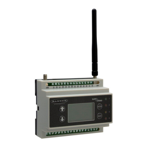
Fischer Panda iControl3 User manual

Panda iControl3_eng.R01 20.10.22
Panda iControl3
Operating Manual
Open-loop and closed-loop control system for Fischer Panda generators

Fischer Panda GmbH
Otto-Hahn-Str. 40
D-33104 Paderborn
Germany
Tel.
Fax.
Hotline
Email
Web
:
:
:
:
:
+49 (0)5254 9202-0
+49 (0)5254 9202-550
+49 (0)5254 9202-767
www.fischerpanda.de
Current revision status
Hardware
Created by
Fischer Panda GmbH - Head of Technical Documentation
Otto-Hahn-Str. 40
33104 Paderborn - Germany
Phone: +49 (0) 5254-9202-0
E-mail: [email protected]
web: www.fischerpanda.de
Copyright
Reproduction and modification of the manual is permitted only after agreement with the manufacturer!
Fischer Panda GmbH, 33104 Paderborn, reserves all rights regarding text and graphics in this document. Details
are given to the best of our knowledge. No liability is accepted for correctness. Please note: technical modifications
aimed at improving the product may be implemented without prior notice. Therefore, it must be ensured prior to
installation that the pictures, diagrams and related material are applicable to the genset supplied. In case of doubt,
verify upon delivery that documentation and equipment match.
Document
Current: Panda iControl3_eng.R01_20.10.22
Replaces: Panda iControl3_eng.R00_08.06.22
Revision Page
R01: Submenu „Service“ moved to the separate document.
Generator Revision Modification Strike Plate Date Upgrade

20.10.22 Inhalt/Contents Seite/Page 1
Inhalt / Contents
Panda iControl3............................................................................................................................................ ....... 1
Current revision status................................................................................................................................ ....... 2
Hardware....................................................................................................................................................... ....... 2
2 Safety instructions for the Panda iControl3......................................................................................... ....... 3
2.1 Personnel........................................................................................................................................ ...... 3
2.2 Safety instructions .......................................................................................................................... ...... 3
3 General operation ................................................................................................................................... ....... 5
3.1 The Panda iControl3 panel ............................................................................................................. ...... 5
3.2 Starting preparation / Checks (daily) .............................................................................................. ...... 6
3.2.1 Marine version ................................................................................................................ ...... 6
3.2.2 Vehicle version ............................................................................................................... ...... 6
3.3 Operation ........................................................................................................................................ ...... 7
3.3.1 Switching the controller on and off ................................................................................. ...... 7
3.3.2 Default display screen .................................................................................................... ...... 8
3.3.3 Operating modes ............................................................................................................ ...... 9
3.3.3.1 Stand-by mode................................................................................................. ...... 9
3.3.3.2 Start-up mode .................................................................................................. ...... 9
3.3.3.3 Override mode ................................................................................................. .... 10
3.3.3.4 Operation mode ............................................................................................... .... 11
3.3.3.5 Panda i-Generator with electro-magnet Clutch (optional)................................ .... 12
3.3.3.6 Stop mode........................................................................................................ ..... 13
3.3.3.7 Autostart mode................................................................................................. .... 13
3.4 Set-up menu .................................................................................................................................. ..... 14
3.4.1 Submenu »Panel« .......................................................................................................... ..... 15
3.4.1.1 Setting the backlight (»Backlight« and »Dimtime«).......................................... .... 15
3.4.1.2 Setting the language (»Language«)................................................................. .... 17
3.4.1.3 Selecting the unit for temperature value outputs (»Units«).............................. ..... 18
3.4.1.4 Setting the network ID...................................................................................... .... 18
3.4.2 Submenu »Generator« ................................................................................................... ..... 19
3.4.2.1 Priming the fuel system (»Prime fuel«) ............................................................ ..... 20
3.4.2.2 Resetting the service interval (»Service«)........................................................ .... 20
3.4.2.3 Activating/deactivating the autostart function (»Autostart«)............................. .... 21
3.4.3 Submenu »Save« ........................................................................................................... ..... 23
3.5 iControl3 Emergency Stop ............................................................................................................. ..... 24
4 Installation ............................................................................................................................................... ..... 25
4.1 Personnel........................................................................................................................................ .... 25
4.1.1 Hazard warnings for installation ..................................................................................... .... 25
4.2 Disposal of the components ........................................................................................................... .... 26
4.2.1 Panda iControl3 panel with installation housing ............................................................. .... 27
4.2.2 Connectors and switches on the Panda iControl3 panel ................................................ .... 27
4.2.2.1 Terminal assignment of the 5-pin Phoenix socket ........................................... ..... 28
4.2.2.2 Terminal assignment of the automatic start socket.......................................... .... 28
4.2.2.3 Terminal assignment Fischer Panda CAN-Bus 2............................................. .... 28
4.2.2.4 Function of the double DIP Switch................................................................... ..... 29
4.3 Dimensions Panda iControl3 panel ............................................................................................... ..... 30
4.4 Wiring of the Panda iControl3 control unit ...................................................................................... .... 31
4.4.1 Terminal assignment of the 42-pin socket ...................................................................... ..... 32
4.5 Dimensions Panda iControl3 control unit ....................................................................................... ..... 33

Seite/Page 2 Inhalt/Contents 20.10.22
Inhalt / Contents
4.6 Master and Slave Panels ............................................................................................................... ..... 34
4.7 Start-up .......................................................................................................................................... ..... 35
5 Maintenance ............................................................................................................................................ ..... 37
5.1 Maintenance of the iControl3 controller .......................................................................................... .... 37
5.1.1 Cleaning the iControl3 controller .................................................................................... .... 37
5.2 Maintenance of the iControl3 remote control panel ........................................................................ .... 37
5.2.1 Cleaning the iControl3 controller .................................................................................... .... 37
6 Warnings and error messages............................................................................................................... ..... 39
6.1 Warnings......................................................................................................................................... .... 39
6.1.1 Examples of warnings on the display: ............................................................................ .... 39
6.1.2 Warning messages ......................................................................................................... ..... 40
6.2 Faults .............................................................................................................................................. .... 40
6.2.1 Error messages .............................................................................................................. ..... 41
6.2.2 Warning and fault thresholds .......................................................................................... .... 42
6.2.3 Bus errors ....................................................................................................................... .... 44
7 Annex ....................................................................................................................................................... ..... 45
7.1 Technical data................................................................................................................................. .... 45
7.1.1 Technical data for iControl3 control unit ......................................................................... .... 45
7.1.2 Technical data for iControl3 remote control panel .......................................................... .... 45
7.2 CO2 balance derived from the emission measuring cycle for engines in accordance with 2016/1628 EC
46

Safety instructions for the Panda iControl3
20.10.22 Kapitel/Chapter 2: Safety instructions for the Panda iControl3 - Seite/Page 3
2. Safety instructions for the Panda iControl3
2.1 Personnel
The settings described here can be performed by the operator unless highlighted differently.
The installation should be implemented by specially trained technical personnel or by authorised workshops (Fischer
Panda Service Points), only.
2.2 Safety instructions
Note!Ensure compliance with the safety instructions in the
Fischer Panda genset manual.
If these instructions are not on hand, they can be requested
from Fischer Panda GmbH, 33104 Paderborn, Germany.
Warning! Automatic start-upAn external signal may trigger an automatic start-up.
Warning!The generator must not be operated with the cover
removed.
If the generator is being installed without a sound insulation
capsule, it must be ensured that all rotating parts (belt pulley,
belts etc.) are covered and protected so that there is no
danger to life and body!
If a sound insulation capsule will be produced at the place of
installation, then well-placed signs must show that the
generator can only be switched on with the capsule closed.
All service, maintenance, or repair work may only be carried
out when the unit is not running.
Warning! Electric voltageElectric voltage - DANGER TO LIFE!
Electric voltages of more than 60V are potentially lethal in
any situation. The rules of the respective regional authority
must be adhered to for installation and maintenance.
For safety reasons, only an electrician may carry out the
installation of the electrical connections of the generator.
Warning!Disconnect battery before working on the generator
The battery must always be disconnected (first the negative
terminal, then the positive terminal) if work on the generator
or electrical system is to be carried out, so that the generator
cannot be unintentionally started.
This applies in particular to systems with an automatic start-
up function. The automatic start-up function shall be
deactivated before starting work.

Safety instructions for the Panda iControl3
Seite/Page 4 - Kapitel/Chapter 2: Safety instructions for the Panda iControl3 20.10.22
The flooding valve must be closed. (For PMS version only.)
Note!Also observe the safety instructions for the other
components of your system.

General operation
20.10.22 Kapitel/Chapter 3: General operation - Seite/Page 5
3. General operation
3.1 The Panda iControl3 panel
The "Panda iControl3 panel" control panel is the control and display unit for the Panda iControl3 control system and
represents the interface between the user and the Panda iControl3 controller. The integrated display serves to
present the most important data of the system as well as warnings and error messages.
The control panel is equipped with four buttons for operating the Panda iControl3 controller:
Fig. 3.1-1: Panda iControl3 panel
01 03
02 04
1. on/off button: Switching the Panda iControl3 controller on and off.
2. start/stop button: Starting and stopping the generator, confirming values in selection menus (Enter key).
3. Cursor-up button: Switching between display screens (up), counting values up in selection menus.
4. Cursor-down button: Switching between display screens (down), counting values down in selection menus.

General operation
Seite/Page 6 - Kapitel/Chapter 3: General operation 20.10.22
3.2 Starting preparation / Checks (daily)
3.2.1 Marine version
1. Oil level control (ideal level: 2/3 MAX).
The level should be about 2/3 of the maximum level of a cold engine.
Further, if installed, the oil level of the oil-cooled bearing must be controlled before each start - see sediment bowl
at generator front cover!.
2. State of cooling water.
The external expansion tank should be filled up to 1/3 of the maximum in a cold state. It is very important that a
large expansion area remains above the cooling water level.
3. Check if sea cock for cooling water intake is open.
For safety reasons, the sea cock must be closed after the generator has been switched off. It should be re-
opened before starting the generator.
4. Check raw water filter.
The raw water filter must be regularly checked and cleaned. The impeller fatigue increases, if residual affects the
raw water intake.
5. Visual inspection.
Control fixing bolts, check hose connectors for leakages, control electrical connections.
6. Switch off the load.
The generator should only be started without load.
7. Open fuel valve, if installed.
8. Close battery main switch (on).
3.2.2 Vehicle version
1. Oil level control (ideal level: 2/3 MAX).
The level should be about 2/3 of the maximum level of a cold engine.
Further, if installed, the oil level of the oil-cooled bearing must be controlled before each start - see sediment bowl
at generator front cover!.
2. State of cooling water.
The external expansion tank should be filled up to 1/3 of the maximum in a cold state. It is very important that a
large expansion area remains above the cooling water level.
3. Visual inspection.
Control fixing bolts, check hose connectors for leakages, control electrical connections.
4. Switch off the load.
The generator should only be started without load.
5. Open fuel valve, if installed.
Close battery main switch (on).

General operation
20.10.22 Kapitel/Chapter 3: General operation - Seite/Page 7
3.3 Operation
3.3.1 Switching the controller on and off
The Panda iControl3 controller is switched on and off by briefly pressing the on/off button on the Panda iControl3
panel.
Fig. 3.3.1-1: .Panda iControl3 boot-up and start screenAfter boot-up, on the start screen information about the
hardware and software release of panel and controller
are displayed.
Fig. 3.3.1-2: Hardware release, software release and revision of the iControl3 panel
Fig. 3.3.1-3: Hardware release, software release and set generator type of the iControl3 control board

General operation
Seite/Page 8 - Kapitel/Chapter 3: General operation 20.10.22
Note!Example for the control board:
Hardware version: C:3 -> iControl3 control board
Software version: 4 -> Release 4 of the iControl3 software,
compatible with iControl3 panel
Generator type: 7 -> Panda 15000i 230 V / 50 Hz PMS
3.3.2 Default display screen
Five seconds after the controller is switched on, the display will change to the default display screen. On the default
display screen, you will find information on the battery voltage, operating hours of the generator, temperatures of
cylinder head, exhaust manifold, and winding, RPM, and the oil pressure status. Also, a bar graph display at the right
hand edge of the display shows the utilisation of the generator in percent.
Data output on the default display screen:
• Battery voltage (supply voltage)
• Status field for operating modes (stand-by, pre-heat, starting, override, running, autostart, stopping)
• Operating hours of the generator
• Oil pressure status
• Cylinder head temperature
• Temperature of exhaust manifold
• Winding temperature
• Speed/RPM
• Utilisation in percent
Fig. 3.3.2-1: Default display screen
04
05
01 02 03
06
07
01. Starter Battery voltage [V]
02. Generator status
03. Oil pressure status [Ok / fault]
04. Utilisation [%]
05. Generator speed [rpm]
06. Temperatures [°C] (Engine, Exhaust and Winding)
07. Operating hours [h]

General operation
20.10.22 Kapitel/Chapter 3: General operation - Seite/Page 9
Note!The Display shows the iControl3 board input voltage.
At generator systems with 12 V starter system this voltage is
equal to the starter battery voltage.
At generator systems with 24 V starter system the starter
battery voltage can not be displayed.
3.3.3 Operating modes
The Panda iControl3 controller offers different operating modes.
3.3.3.1 Stand-by mode
After the controller is switched on with the on/off button, the system is in stand-by mode. This is indicated by the
output "Standby" in the status field in the top right corner of the default display screen.
In this operating mode, the system can be switched off with the on/off button, and the generator can be started up
with the start/stop button. With the cursor buttons, the service information screen can be accessed.
Fig. 3.3.3.1-1: Service information screen
The total operating hours of the generator are given on the default display screen and on the service information
screen. By actuating the cursor-up button in stand-by mode, the service screen can be accessed.
This screen is marked with a screwdriver/spanner symbol. Here, the time until the next service and the average load
in percent are given. By actuating the cursor-up or cursor-down button, you can return to the default screen.
Note!With the dynamic operation hours the service interval can be
raised up to 30 % (200 h max.). Make sure that the dynamic
operation hours are not reset accidently between the service
interval, see “Resetting the service interval (»Service«)”
on page 20.
In the set-up menu of the controller, you can reset the service interval after performing maintenance, see “Set-up
menu” on page 14.
3.3.3.2 Start-up mode
The start-up mode represents the transition from stand-by mode to operation mode, i.e., generator operation. By
actuating the start/stop button in stand-by mode, you can initiate the start-up process of the generator.
The pre-heating is the first step. During this stage, the status field at the top right of the default display screen shows
the word "Preheat".

General operation
Seite/Page 10 - Kapitel/Chapter 3: General operation 20.10.22
Fig. 3.3.3.2-1: Default display screen during pre-heatingThe pre-heating is always implemented for a duration of
10 seconds, regardless of the cylinder head temperature.
In temperatures below 0°C, the pre-heating time is always 40
seconds.
Fig. 3.3.3.2-2: Default display screen during start-up After pre-heating, the starter is initiated, accompanied by
the text output "Starting" in the status field of the default
display screen.
Note!The controller will only perform one starting attempt. If
the generator could not be started, the text output
"Starting fails" informs you of the failure of the generator
starting attempt.
Fig. 3.3.3.2-3: Error message »Starting fails«Acknowledging the message with the start/stop button on the
Panda iControl3 panel will return the system to stand-by
mode.
Attention!If there is difficulty in starting - close the seacock (Panda
Marine Generators only)
If the generator engine does not start immediately and further start attempts are necessary, then the seacock MUST
be closed (i.e. for ventilating the fuel lines ect.) The cooling water impeller pump turns automatically and draws coo-
ling water as long as the motor is turning. If the diesel motor is running, the cooling water is blown out by the exhaust
system gases. The cooling water cannot be pressed through the exhaust as long as the diesel motor does not run at
sufficient speed. This leads to severe motor damage.
Open the sea valve as soon as the generator is started.
3.3.3.3 Override mode
The override mode follows directly after the successful start-up of the generator. In this mode, no fault analysis is
performed. The duration of the override mode is 10 seconds. The status indicator on the display reads "Override".

General operation
20.10.22 Kapitel/Chapter 3: General operation - Seite/Page 11
Fig. 3.3.3.3-1: Default display screen in override mode
3.3.3.4 Operation mode
Operation mode signifies the operating mode in which the generator is running and all operating data are within their
normal range. The status field of the default display screen shows "Running".
Fig. 3.3.3.4-1: Default display screen in operation modeIn operation mode, the electrical load is given on the
right hand side of the default display screen and in the
inverter screen as a bar graph. The bar graph merely
provides a guide value for the load of the generator and
gives the values as a percentage.
Fig. 3.3.3.4-2: Second screen in operating mode
Display screen for single phase generators
Fig. 3.3.3.4-3: Inverter screen in operation mode (single phase)With the single phase i-series generators, there is an
additional screen in operation mode for the inverter data.
This screen provides the current inverter output voltage,
current and the inverter temperature.
You can access the inverter screen by actuating the cursor-
down button while in operation mode.

General operation
Seite/Page 12 - Kapitel/Chapter 3: General operation 20.10.22
Display screen for 3-phase generators
Fig. 3.3.3.4-4: Inverter screen in operation mode (3-phase)With the 3-phase i-series generators, there is an additional
screen in operation mode for the inverter data. This screen
provides the latest inverter output voltage of the single
phases with the matching conductor current and the circuit
board temperature. The inverter will be switched off at a
circuit board temperature of 75 °C.
You can access the inverter screen by actuating the cursor-
down button while in operation mode.
3.3.3.5 Panda i-Generator with electro-magnet Clutch (optional)
Attention!During the activation of the electro-magnetic clutch, the
iControl3 raise the generator speed to maximum.
After the clutch is released, the generator speed will drop to
normal.

General operation
20.10.22 Kapitel/Chapter 3: General operation - Seite/Page 13
3.3.3.6 Stop mode
By activating the start/stop button in operation mode, i.e., while the generator is running, you will stop the generator.
After stopping the generator, the system will return to stand-by mode. The display status field reads „Stopping“.
With marine generators and a cylinder head temperature greater than 70 °C (for example after a long time running
with high load) the iControl3 starts a stopping delay timer. The Display shows „Cooldown“ in the status field.
This does not exist with vehicle generators, since the fan cannot work during cooldown.
During this time the iControl3 system will shut of the PMGi and run the engine at idle speed. During the delay time
an automatic start request will be ignored.
After the delay time, the generator will be stopped automatically.
You can interrupt the delay time by pressing the start/stop button. (Not recommend by Fischer Panda. The Engine
may overheat)
Attention!Never use an emergency stop switch for a regular stop
of the generator.
The engine may overheat and can be damaged/destroyed
Note! Manual start in autostart modeIf the generator is manually started up and stopped while in
automatic start-up mode, it will switch to stand-by mode for
safety reasons.
If necessary, the autostart mode must be reactivated.
3.3.3.7 Autostart mode
The Panda iControl3 panel is equipped with an autostart function. A jumper between pin 6 (AS) and pin 7 (AS) of the
Phoenix jack of the control panel starts up the generator with a delay of 5 seconds when the autostart function is
active. Removing the jumper will stop the generator - also with a delay of 5 seconds.
The autostart function must be activated in the set-up menu. To activate the autostart function, see “Activating/
deactivating the autostart function (»Autostart«)” on page 21.
Fig. 3.3.3.7-1: Default display screen in autostart modeThe display status field reading "Autostart" indicates
that the autostart function is active, or, if it reads
"Standby", this means that the autostart function was
deactivated.
Warning! Automatic start-upThe autostart function will remain active even after the
controller is switched off and on again with the on/off
button. If the autostart function is no longer required, the
function must be deactivated, see “Activating/
deactivating the autostart function (»Autostart«)” on
page 21.
Note! Manual start in autostart modeIf the generator is manually started up and stopped while
in automatic start-up mode, it will switch to stand-by
mode for safety reasons.
If necessary, the autostart mode must be reactivated.

General operation
Seite/Page 14 - Kapitel/Chapter 3: General operation 20.10.22
3.4 Set-up menu
In the set-up menu, a series of parameters concerning panel, generator and service topics can be modified directly
using the control panel.
The set-up menu consists of 3 submenus and an option to save changes.
Fig. 3.4-1: Submenus of the set-up menu
Fig. 3.4-2: Versions are being displayed on the start screent
Calling up the set-up menu:
1. Switch on the iControl3 system using the on/off button.
2. Press the cursor-up button while the hardware/software
versions are being displayed on the start screen.
The start page of the set-up menu is displayed with its submenus:
Fig. 3.4-3: Start page of the set-up menu• Panel
• Generator
• Service
• Save
The submenus are explained in the following chapters.
Note!The submenu »Service« is blocked and can only be
accessed by trained personnel and Fischer Panda
employees.
Note!In all submenus, set the desired values using the cursor
buttons, then confirm your settings with the start/stop button.
After setting all parameters, you can exit the set-up menu with the menu item "Save". In doing so, all settings
entered in the sub-menus Backlight 1, Backlight 2, Dimtime, Language, Units and Network ID are saved.
After saving the changes, the iControl3 restarts and the start screen is displayed. After that all changes will take
effect.
Menu item Settings range for
Panel Parameters concerning the iControl3 panel
Generator Parameters concerning the generator control iControl3
Service Parameters concerning service topics
Save Saving the values and restarting the iControl3

General operation
20.10.22 Kapitel/Chapter 3: General operation - Seite/Page 15
3.4.1 Submenu »Panel«
Fig. 3.4.1-1: Set-up menu, highlighted *Panel*Calling up the submenu »Panel«:
• Select *Panel* and confirm with the start/stop button.
Fig. 3.4.1-2: Submenu »Panel« highlighted *Backlight 1*With the cursor-up and cursor-down buttons, you can
navigate through the menu. The currently selected menu
item is marked with two asterisks (*), e. g. *Backlight 1*.
Fig. 3.4.1-3: Submenu »Panel«, highlighted *Back*Set-up submenu »Panel« with item highlighted: *Back*
Note!The start/stop button is used to confirm the selected item in
the set-up menu. Confirming the row marked with the *
accesses the selected submenu.
Fig. 3.4.1-4: Items of the submenu »Panel«
3.4.1.1 Setting the backlight (»Backlight« and »Dimtime«)
The brightness of the display backlight of the Panda iControl3 panel can be varied from 0 to 100 % in 1 % steps.
Also, the display can be dimmed with a timer if no button is actuated on the control panel for a parameter is able
Menu item Settings range for
Backlight 1 Setting the brightness value for the standard backlighting to 0-100 %
Backlight 2 Setting the brightness value for the dimmed backlighting to 0-100 %
Dimtime (dimming time) Time until the display switches to dimmed mode, 0-255 s (corresponds to 0-4 min), 0= lighting is always dimmed
Language Language selection (English, German and French available)
Units Switches the display between °C and °F
Network Settings for the network ID of the panel
Back Exiting the set-up submenu »Panel«

General operation
Seite/Page 16 - Kapitel/Chapter 3: General operation 20.10.22
period. To adjust the default brightness and the dimmed brightness, the set-up submenu »Panel« offers the items
"Backlight 1" (default brightness) and "Backlight 2" (dimmed brightness). These service menu screens are
highlighted with the light bulb symbol:
Fig. 3.4.1.1-1: Submenu »Panel«, highlighted *Backlight 1*• Select *Backlight 1* and confirm with the start/stop button.
• Enter the value for the backlight. Values between 0 and
100 % are possible.
Fig. 3.4.1-2: Screen for setting the brightness of the display backlight
Note!Setting the value for the dimmed brightness (Backlight 2)
works in the same way.
01
04
03
01. Increase the value (Cursor-up button) [%]
02. Decrease the value (Cursor-down button) [%]
03. Set value [%]
04. Confirm the set value (start/stop button)
02

General operation
20.10.22 Kapitel/Chapter 3: General operation - Seite/Page 17
Fig. 3.4.1.1-3: Submenu »Panel«, highlighted *Dimtime*The period after which the backlight switches to the dimmed
level can be specified with the menu item "Dimtime".
• Select *Dimtime* and confirm with the start/stop button.
Fig. 3.4.1.1-4: Screen for setting the dimtime• Enter the value for the dimtime. Values between 0 and
255 s are possible.
3.4.1.2 Setting the language (»Language«)
Fig. 3.4.1.2-1: Submenu »Panel«, highlighted *Language*• Select *Language* and confirm with the start/stop button.
Fig. 3.4.1.2-2: Selected language, highlighted *English*Settings options:
• English
• German (Not yet available. Planned in the future)
• French (Not yet available. Planned in the future)

General operation
Seite/Page 18 - Kapitel/Chapter 3: General operation 20.10.22
3.4.1.3 Selecting the unit for temperature value outputs (»Units«)
Temperature values can be displayed in degrees Celsius [°C] or in degrees Fahrenheit [°F].
Fig. 3.4.1.3-1: Submenu »Panel«, highlighted *Units*• Select *Units* and confirm with the start/stop button.
Fig. 3.4.1.3-2: Selected unit, highlighted *Celsius*Settings options:
*Celsius*: Output of all temperatures in degrees Celsius [°C]
*Fahrenheit*: Output of all temperatures in degrees Fahren-
heit [°F]
3.4.1.4 Setting the network ID
Stop! Network ID must not be modifiedSettings in this area must only be entered by Fischer
Panda associates and Fischer Panda service points.
Changing the network ID can result in malfunction.
Fig. 3.4.1.4-1: Submenu »Panel«, highlighted *Network*• Select *Network* and confirm with the start/stop button.
Fig. 3.4.1.4-2: Screen for setting the network ID• Enter the network ID.
Table of contents
Other Fischer Panda Controllers manuals
