After entering changes, it is recommended to step through the menu options until the option donE is displayed to exit the menu
mode; the menu will display donE.
NOTE: Changes made in the Menu will be saved when the menu is exited.
Table 3: Menu Mode Options Specifications
Display Menu Description
Ch Channel The Channel Number menu allows the user to change the channel by
using the up or down button. The channel number must be set to the
same channel number as the Primary Transmitter or other Satellite
Transmitter broadcast channel.
tESt Test The Test menu allows the user to hear audible beeps with a valid
time/date reception. This will occur 5 seconds after the test menu is
selected. It will continue to be in this mode until the menu button is
pressed again, leaving the menu mode and returning to normal mode.
LtU Last Time Update The Last Time Update menu allows the user to see the last time
update, time and date (cycles every second). This will occur 5 seconds
after last time update menu is selected. The unit will remain in this
mode for a minute, wherein it will time out and return to the menu
mode.
Soft Software Revision: The Software Revision menu allows the user to see the software revi-
sion on the unit. This will occur 5 seconds after last time update
menu is selected. The unit will remain in this mode for a minute,
wherein it will time out and return to the menu mode.
dst Daylight Saving Time Calendar The Daylight Saving Time Calendar menu allows the user to see the
current Daylight Saving Time calender in use. This will occur 5
seconds after last time update menu is selected. The unit will remain
in this mode for a minute, wherein it will time out and return to the
menu mode.
donE Done The Done menu allows the user to exit the menu mode. This will
occur 5 seconds after the done menu is selected returning to the
normal mode saving all settings.
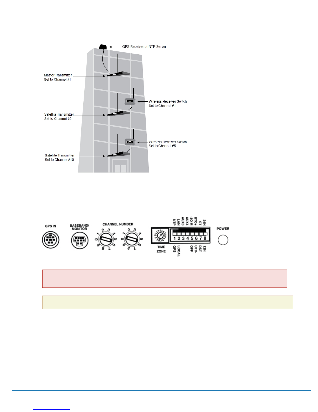
Internal Dip Switch Configuration - Time and Channel Scan Settings
The Receiver Switch has an internal dip switch panel that sets the configuration for the time/date display, automatic British Summer
Time, and automatic channel scanning.
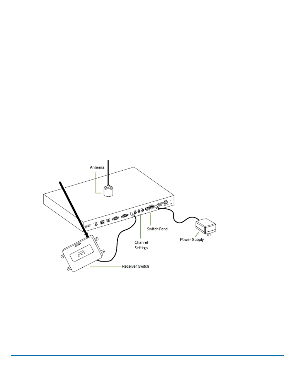
To access the dip switch panel, remove the unit's large cover. Remove the switch cover by removing the two Phillip head screws,
located in the upper leftt and lower right of the unit. The dip switch panel is located on the top of the unit; identified by the blue
switch panel.
CAUTION: Except when setting the Dip Switch Options, the unit cover should remain closed and secure at all times.
Table 4: Dip Switch Option Specifications
Switch Sets ON Position OFF Position
2Time/Date displays only the
time.
displays current time for 8 seconds and the
date for 2 seconds.
312/24 Hour displays the time in
24 hour format.
displays the time in 12 hour format.
4RF Channel Scan enable the scan and
look for a suitable
channel.
disable the scan and only look on the selected
channel for time/date/event info.
Primex Wireless Satellite Installation & User Guide 10
Configure and Install Satellite Transmitter Internal Dip Switch Configuration - Time and Channel Scan Settings