10
7
9
8
10
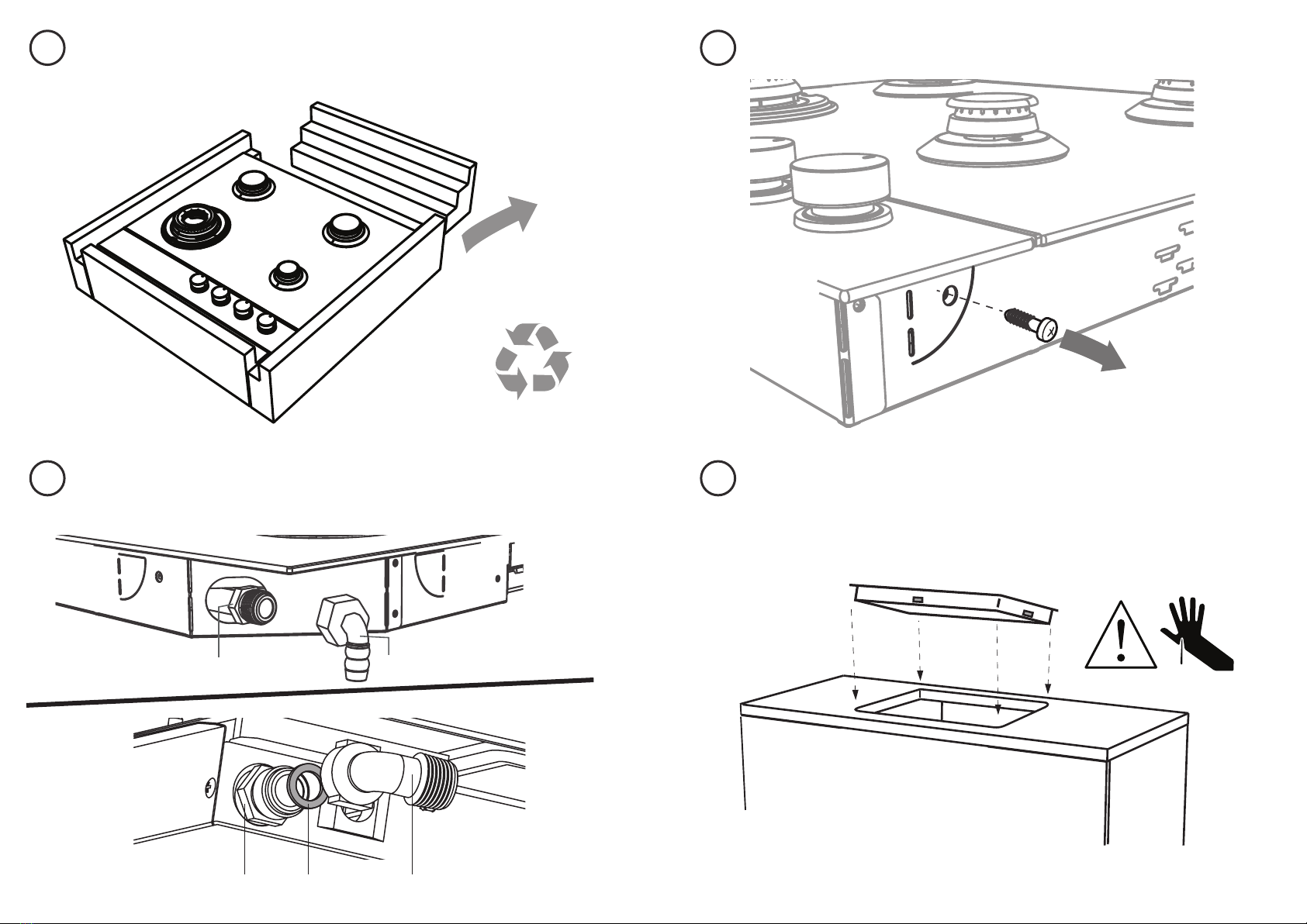
DISCARD PACKAGING
FIT THE ELBOW AND WASHER
REMOVE THE TWO TRANSIT SCREWS
LOWER GENTLY INTO THE CUTOUT
GAS
ON
GAS
ON
PTFE
⁄”NPT
500 mm
50 mm
1
2
500 mm
25 mm
25 mm
500 mm
NG
NG LPG
LPG
20-50 mm
½“ BSP ½“ BSP
x 4
1
1
2
2
16-20mm 20-30mm
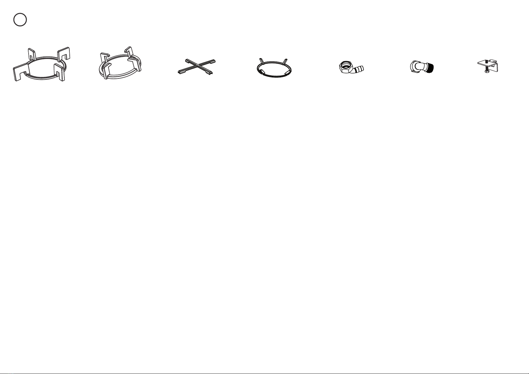
Fibre washer
Floating nut Elbow (½”BSP external thread)
LPG test point adaptor (if using LPG)
min
S
A
R
min
A
F
S
REAR CLAMPS FRONT CLAMPS
40 mm
40 mm
30 mm
30 mm
30 mm
30 mm
Foam Tape
Adhesive side
Fibre washer
Floating nut Elbow (½”BSP external thread)
NG Models
ALL Models
Make sure the connection point will be accessible with the cooktop installed.
To enable the gas supply to be readily shut o by the customer, make sure the connection
is tted with an isolating valve close to the cooktop.
Make sure to t the supplied
washer and regulator.
Adjust to obtain a test point
pressure of 1 kPa with the two
semi-rapid burners operating at
highest setting.
Ensure the hose is long enough to allow for removal of cooktop for servicing.
Make sure the connector is located as shown in step 3 CLEARANCE DIMENSIONS.
The hose assembly must be AS/NZS 1869 Class B or D certied, with an Rp ½”(ISO 71) female thread connection.
The hose assembly must be as short as practicable and comply with relevant AS 5601/NZS 5261 requirements.
The hose must not be kinked, subjected to abrasion or permanently deformed.
The hose must not be near or in contact with any hot surfaces
(e.g. base of metal hotlplate, ue, or chassis of underbench oven etc.)
If connecting the gas with a exible hose:
LPG Models
check all connections
Make sure to t the supplied
washer and test point adaptor.
Make sure the supply pressure
is regulated to 2.75 kPa, with
the two semi-rapid burners
operating at highest setting.
Washer Washer
yellow tiplifting o
good ame
Arrow
x 4
x 4
30-40mm 40mm+
Recycle responsibly
GAS
ON
GAS
ON
PTFE
⁄”NPT
500 mm
50 mm
1
2
500 mm
25 mm
25 mm
500 mm
NG
NG LPG
LPG
20-50 mm
½“ BSP ½“ BSP
x 4
1
1
2
2
16-20mm 20-30mm
Fibre washer
Floating nut Elbow (½”BSP external thread)
LPG test point adaptor (if using LPG)
min
S
A
R
min
A
F
S
REAR CLAMPS FRONT CLAMPS
40 mm
40 mm
30 mm
30 mm
30 mm
30 mm
Foam Tape
Adhesive side
Fibre washer
Floating nut Elbow (½”BSP external thread)
NG Models
ALL Models
Make sure the connection point will be accessible with the cooktop installed.
To enable the gas supply to be readily shut o by the customer, make sure the connection
is tted with an isolating valve close to the cooktop.
Make sure to t the supplied
washer and regulator.
Adjust to obtain a test point
pressure of 1 kPa with the two
semi-rapid burners operating at
highest setting.
Ensure the hose is long enough to allow for removal of cooktop for servicing.
Make sure the connector is located as shown in step 3 CLEARANCE DIMENSIONS.
The hose assembly must be AS/NZS 1869 Class B or D certied, with an Rp ½”(ISO 71) female thread connection.
The hose assembly must be as short as practicable and comply with relevant AS 5601/NZS 5261 requirements.
The hose must not be kinked, subjected to abrasion or permanently deformed.
The hose must not be near or in contact with any hot surfaces
(e.g. base of metal hotlplate, ue, or chassis of underbench oven etc.)
If connecting the gas with a exible hose:
LPG Models
check all connections
Make sure to t the supplied
washer and test point adaptor.
Make sure the supply pressure
is regulated to 2.75 kPa, with
the two semi-rapid burners
operating at highest setting.
Washer Washer
yellow tiplifting o
good ame
Arrow
x 4
x 4
30-40mm 40mm+
Repeat on the other side
GAS
ON
GAS
ON
PTFE
⁄”NPT
500 mm
50 mm
1
2
500 mm
25 mm
25 mm
500 mm
NG
NG LPG
LPG
20-50 mm
½“ BSP ½“ BSP
x 4
1
1
2
2
16-20mm 20-30mm
Fibre washer
Floating nut Elbow (½”BSP external thread)
LPG test point adaptor (if using LPG)
min
S
A
R
min
A
F
S
REAR CLAMPS FRONT CLAMPS
40 mm
40 mm
30 mm
30 mm
30 mm
30 mm
Foam Tape
Adhesive side
Fibre washer
Floating nut Elbow (½”BSP external thread)
NG Models
ALL Models
Make sure the connection point will be accessible with the cooktop installed.
To enable the gas supply to be readily shut o by the customer, make sure the connection
is tted with an isolating valve close to the cooktop.
Make sure to t the supplied
washer and regulator.
Adjust to obtain a test point
pressure of 1 kPa with the two
semi-rapid burners operating at
highest setting.
Ensure the hose is long enough to allow for removal of cooktop for servicing.
Make sure the connector is located as shown in step 3 CLEARANCE DIMENSIONS.
The hose assembly must be AS/NZS 1869 Class B or D certied, with an Rp ½”(ISO 71) female thread connection.
The hose assembly must be as short as practicable and comply with relevant AS 5601/NZS 5261 requirements.
The hose must not be kinked, subjected to abrasion or permanently deformed.
The hose must not be near or in contact with any hot surfaces
(e.g. base of metal hotlplate, ue, or chassis of underbench oven etc.)
If connecting the gas with a exible hose:
LPG Models
check all connections
Make sure to t the supplied
washer and test point adaptor.
Make sure the supply pressure
is regulated to 2.75 kPa, with
the two semi-rapid burners
operating at highest setting.
Washer Washer
yellow tiplifting o
good ame
Arrow
x 4
x 4
30-40mm 40mm+
Floating nut Elbow (1/2” BSP thread) & Washer
GAS
ON
GAS
ON
PTFE
⁄”NPT
500 mm
50 mm
1
2
500 mm
25 mm
25 mm
500 mm
NG
NG LPG
LPG
20-50 mm
½“ BSP ½“ BSP
x 4
1
1
2
2
16-20mm 20-30mm
Fibre washer
Floating nut Elbow (½”BSP external thread)
LPG test point adaptor (if using LPG)
min
S
A
R
min
A
F
S
REAR CLAMPS FRONT CLAMPS
40 mm
40 mm
30 mm
30 mm
30 mm
30 mm
Foam Tape
Adhesive side
Fibre washer
Floating nut Elbow (½”BSP external thread)
NG Models
ALL Models
Make sure the connection point will be accessible with the cooktop installed.
To enable the gas supply to be readily shut o by the customer, make sure the connection
is tted with an isolating valve close to the cooktop.
Make sure to t the supplied
washer and regulator.
Adjust to obtain a test point
pressure of 1 kPa with the two
semi-rapid burners operating at
highest setting.
Ensure the hose is long enough to allow for removal of cooktop for servicing.
Make sure the connector is located as shown in step 3 CLEARANCE DIMENSIONS.
The hose assembly must be AS/NZS 1869 Class B or D certied, with an Rp ½”(ISO 71) female thread connection.
The hose assembly must be as short as practicable and comply with relevant AS 5601/NZS 5261 requirements.
The hose must not be kinked, subjected to abrasion or permanently deformed.
The hose must not be near or in contact with any hot surfaces
(e.g. base of metal hotlplate, ue, or chassis of underbench oven etc.)
If connecting the gas with a exible hose:
LPG Models
check all connections
Make sure to t the supplied
washer and test point adaptor.
Make sure the supply pressure
is regulated to 2.75 kPa, with
the two semi-rapid burners
operating at highest setting.
Washer Washer
yellow tiplifting o
good ame
Arrow
x 4
x 4
30-40mm 40mm+
Model may vary from illustrations shown
Floating nut Fibre washer Elbow (1/2” BSP external thread)
HONG KONG
SINGAPORE
GAS
ON
GAS
ON
PTFE
⁄”NPT
500 mm
50 mm
1
2
500 mm
25 mm
25 mm
500 mm
NG
NG LPG
LPG
20-50 mm
½“ BSP ½“ BSP
x 4
1
1
2
2
16-20mm 20-30mm
Fibre washer
Floating nut Elbow (½”BSP external thread)
LPG test point adaptor (if using LPG)
min
S
A
R
min
A
F
S
REAR CLAMPS FRONT CLAMPS
40 mm
40 mm
30 mm
30 mm
30 mm
30 mm
Foam Tape
Adhesive side
Fibre washer
Floating nut Elbow (½”BSP external thread)
NG Models
ALL Models
Make sure the connection point will be accessible with the cooktop installed.
To enable the gas supply to be readily shut o by the customer, make sure the connection
is tted with an isolating valve close to the cooktop.
Make sure to t the supplied
washer and regulator.
Adjust to obtain a test point
pressure of 1 kPa with the two
semi-rapid burners operating at
highest setting.
Ensure the hose is long enough to allow for removal of cooktop for servicing.
Make sure the connector is located as shown in step 3 CLEARANCE DIMENSIONS.
The hose assembly must be AS/NZS 1869 Class B or D certied, with an Rp ½”(ISO 71) female thread connection.
The hose assembly must be as short as practicable and comply with relevant AS 5601/NZS 5261 requirements.
The hose must not be kinked, subjected to abrasion or permanently deformed.
The hose must not be near or in contact with any hot surfaces
(e.g. base of metal hotlplate, ue, or chassis of underbench oven etc.)
If connecting the gas with a exible hose:
LPG Models
check all connections
Make sure to t the supplied
washer and test point adaptor.
Make sure the supply pressure
is regulated to 2.75 kPa, with
the two semi-rapid burners
operating at highest setting.
Washer Washer
yellow tiplifting o
good ame
Arrow
x 4
x 4
30-40mm 40mm+