manuals.online logo
Brands
  1. Home
  2. •
  3. Brands
  4. •
  5. Crestron
  6. •
  7. Conference System
  8. •
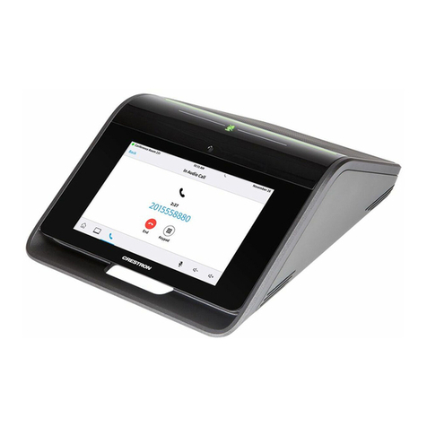
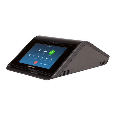
  9. Crestron Mercury CCS-UCA-SMK Dimensional drawing

Crestron Mercury CCS-UCA-SMK Dimensional drawing

Other Crestron Conference System manuals

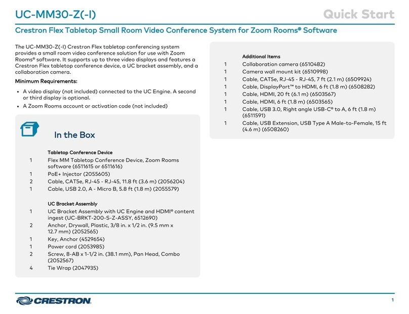
Crestron UC-M70-NC-Z User manual

Crestron

Crestron UC-M70-NC-Z User manual

Crestron UC-B31-T User manual

Crestron

Crestron UC-B31-T User manual

Crestron UC-2 User manual

Crestron

Crestron UC-2 User manual

Crestron UC-B160-Z User manual

Crestron

Crestron UC-B160-Z User manual

Crestron UC-MM30-TA User manual

Crestron

Crestron UC-MM30-TA User manual

Crestron UC-M70-U User manual

Crestron

Crestron UC-M70-U User manual

Crestron UC-MX150-Z User manual

Crestron

Crestron UC-MX150-Z User manual

Crestron UC-MX50-T User manual

Crestron

Crestron UC-MX50-T User manual

Crestron UC-BX30-T-WM User manual

Crestron

Crestron UC-BX30-T-WM User manual

Crestron UC-MM30-A-T User manual

Crestron

Crestron UC-MM30-A-T User manual

Crestron SR Owner's manual

Crestron

Crestron SR Owner's manual

Crestron Mercury CCS-UC-1 User manual

Crestron

Crestron Mercury CCS-UC-1 User manual

Crestron UC-BX31-T-WM-INDIA User manual

Crestron

Crestron UC-BX31-T-WM-INDIA User manual

Crestron UC-BRKT-100-SD-Z-ASSY User manual

Crestron

Crestron UC-BRKT-100-SD-Z-ASSY User manual

Crestron UC-FCMX Series User manual

Crestron

Crestron UC-FCMX Series User manual

Crestron UC-MX70-NC-Z User manual

Crestron

Crestron UC-MX70-NC-Z User manual

Crestron UC-SB1-CAM User manual

Crestron

Crestron UC-SB1-CAM User manual

Crestron UC-C100-T User manual

Crestron

Crestron UC-C100-T User manual

Crestron 4K DigitalMedia  DMPS3-4K-150-C Dimensional drawing

Crestron

Crestron 4K DigitalMedia DMPS3-4K-150-C Dimensional drawing

Crestron UC-C160-Z User manual

Crestron

Crestron UC-C160-Z User manual

Crestron UC-MMX30-Z User manual

Crestron

Crestron UC-MMX30-Z User manual

Crestron UC-C160-T User manual

Crestron

Crestron UC-C160-T User manual

Crestron UC-BX31-T-WM User manual

Crestron

Crestron UC-BX31-T-WM User manual

Crestron UC-M130-Z User manual

Crestron

Crestron UC-M130-Z User manual

Popular Conference System manuals by other brands

Jabbla Tellus 6 operating instructions

Jabbla

Jabbla Tellus 6 operating instructions

LY International Electronics H-9500 Series Installation and operating manual

LY International Electronics

LY International Electronics H-9500 Series Installation and operating manual

RADVision Scopia XT1000 user guide

RADVision

RADVision Scopia XT1000 user guide

AT&T MERLIN LEGEND Reference

AT&T

AT&T MERLIN LEGEND Reference

Polycom RealPresence Group Series setup sheet

Polycom

Polycom RealPresence Group Series setup sheet

ProSoft Technology AN-X4-AB-DHRIO user manual

ProSoft Technology

ProSoft Technology AN-X4-AB-DHRIO user manual

Sony PCS-I150 Operation guide

Sony

Sony PCS-I150 Operation guide

Middle Atlantic Products VTC Series instruction sheet

Middle Atlantic Products

Middle Atlantic Products VTC Series instruction sheet

AVT MAGIC AC1 Go Configuration guide

AVT

AVT MAGIC AC1 Go Configuration guide

Prentke Romich Company Vanguard Plus Setting up and using

Prentke Romich Company

Prentke Romich Company Vanguard Plus Setting up and using

Speakerbus iD 712 user guide

Speakerbus

Speakerbus iD 712 user guide

Trelleborg SafePilot CAT PRO user guide

Trelleborg

Trelleborg SafePilot CAT PRO user guide

Sennheiser ADN instruction manual

Sennheiser

Sennheiser ADN instruction manual

ADTRAN NetVanta 7100 Configuration guide

ADTRAN

ADTRAN NetVanta 7100 Configuration guide

AINA PTT Voice Responder quick guide

AINA

AINA PTT Voice Responder quick guide

Yamaha ProjectPhone PJP-100H owner's manual

Yamaha

Yamaha ProjectPhone PJP-100H owner's manual

vissonic VLI Series user manual

vissonic

vissonic VLI Series user manual

Panasonic KX-VC500 user manual

Panasonic

Panasonic KX-VC500 user manual

manuals.online logo
manuals.online logoBrands
  • About & Mission
  • Contact us
  • Privacy Policy
  • Terms and Conditions

Copyright 2025 Manuals.Online. All Rights Reserved.

DO GUIDE
CCS-UCA-SMK
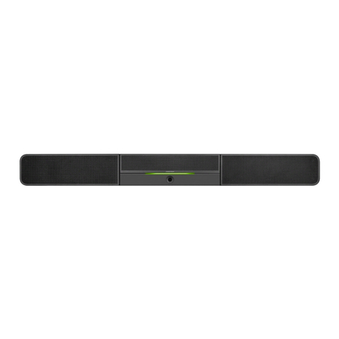
Swivel Mount Kit for Crestron Mercury™ Tabletop Conference System
DO Prepare the Mounting Location
NOTE: The mounting surface should have a thickness of 1" (25 mm) to 1-3/8" (34 mm).
The kit includes a template that is used to mark the location of the mounting hole on top of the mounting surface, and the location of the stop plate under the
mounting surface. When using the template, make sure the arrow on the template points toward the front edge of the mounting surface.
1. Secure the template to a mounting location that allows the full pivot of the device on the top of the mounting surface and a close mounting location for
accessories beneath the mounting surface.
2. Place 2" painters tape (not included) on the hole location and mark the hole on the tape.
3. Drill a 1-3/16" (30 mm) mounting hole in the marked location on the tape.
4. Relocate the template to the underside of the mounting surface and orient it so that the arrow on the template points toward the front edge of the table.
Verify that the template location of the stop plate permits the Crestron Mercury™ device to swivel.
DO Install the Cable Retention Bracket
NOTE: If a cable retention plate is already installed, it must be removed. For new installations, skip to step 3. Otherwise, follow this procedure:
1. Use two small at head screwdrivers to slowly pry off the existing retention plate.
2. Remove all adhesive residue from the surface.
3. Clean the surface with an alcohol wipe (not supplied).
4. Remove the paper liner from the back of the cable retention bracket.
5. Install the cable retention bracket as shown in the following diagram.
6. Press rmly on the cable retention bracket for approximately 30 seconds.
CAUTION: When turning over the device, place the device on a soft surface to avoid damage to the unit.
DO Connect the Device
1. Drill pilot holes with a 1/8" bit in the stop plate’s mounting location and attach the stop plate to the underside of the mounting surface with the six
included 8-8B x 1/2" screws.
2. Place the swivel tube plate on the mounting surface.
3. Route all cables that connect to the Crestron Mercury device from underneath the mounting surface through the swivel kit hardware as shown below.
Cables with larger connectors should be routed rst, followed by cables with smaller connectors.
If the HDMI®input cable and the USB cable are to be routed to the front of the Crestron Mercury device, do not route these cables through the swivel kit
hardware.
DO Check the Box
QUANTITY PRODUCT COLOR PART NUMBER
1 Bit, Slotted 1/4" W 2049730
1 Bit, Slotted 23/64" W 2049474
1Bracket, Cable Retention 4526653
1 Cable, HDMI, Male to Female Extender 2049637
4 Insert, Metal, M7, 6-32 Thread, 0.28" L 2049476
2 Insert, Metal, M10, 10-32 Thread, 0.41" L 2049328
2Nut, 1-1/8"-12 2049390
2 Screw, 4-40 x 1/4", Pan Head, Phillips Black 2007158
2 Screw, 6-32 x 1/2", Pan Head, Phillips Black 2007238
2 Screw, 6-32 x 1", Truss Head, Phillips Black 2049649
6 Screw, 8-8B x 1/2", Pan Head, Phillips 2017784
2 Screw, 8-32 x 1/8", Cap Head, Socket Black 2017634
2 Screw, 10-32 x 1", Pan Head, Phillips Black 2049391
1 Stop Plate, Swivel, with Screws 4526651
1Template, Cutout 4526654
5Tie Wrap 2047935
1 Washer, Cork, 2.0" OD, 1.19" ID, 0.06" TH 2049448
1Washer, Keyed 4526609
1 Washer, Metal, 2.0" OD, 1.19" ID, 0.10" TH 2049389
1 Washer, Rubber, 2.0" OD, 1.19" ID, 0.06" TH 2049449
If the Crestron Mercury device’s HDMI OUT port is to be used, perform the following procedure:
a. Connect the HDMI Extension Cable (2049637) to the HDMI OUT port.
b. Route the cable extender through the swivel tube.
c. Connect the HDMI cable provided with the Crestron Mercury device to the cable extender.
4. Make the necessary connections to the device. Refer to the DO Guide or Installation Guide included with the Crestron Mercury system.
5. Use the included tie wraps to secure all of the cables to the cable retention bracket that was installed in “DO Install the Cable Retention Bracket.”
6. If the front USB and HDMI input connections are to be used, press the USB and HDMI IN cables into the channels on the underside of the device as
shown in the following diagram (cables removed for clarity) so that the connectors can be routed to the front of the device.
Stop plate
Cork washer
Keyed washer
Nuts (2)
Permanently installed
limiting screws
Rubber washer
Flat washer
Thread cables
through here.
Standard Wiring Zoom Wiring
Cable retention bracket
Route USB
cable here
Route HDMI
cable here
DO GUIDE DOC. 7882B (2049471) 10.17
Specications subject to change without notice.
DO Attach the Swivel Tube Plate to the Device
NOTE: A manual bit screwdriver (not included) is required for this procedure.
1. Install the inserts as shown in the following diagram (cables removed for clarity).
NOTE: Due to variances in manufacturing, these insert locations use either the small diameter
inserts or the large diameter inserts. Use the inserts (and matching screws) that t into the holes in
the device’s chassis.
NOTE: The M7 inserts drop down into the two center holes in the base prior to tightening.
a. Place the correct insert in the proper location with the slotted end on top.
b. Use a manual bit screwdriver to secure the inserts to the Crestron Mercury device by turning
each insert until it locks itself snugly into the base.
• For the smaller insert, use the included 1/4" slotted bit to turn the insert.
• For the larger insert, use the included 23/64" slotted bit to turn the insert.
2. Refer to the following diagram (cables removed for clarity) to attach the swivel tube plate to the
device.
CAUTION: Ensure that all screws are fully seated to avoid damage to the mounting surface.
NOTE: Use the screws that t the inserts installed in step 1.
NOTE: To avoid bending the swivel tube plate, do not overtorque the screws.
DO Secure the Device to the Mounting Surface
1. Slide the included hardware onto the swivel tube as shown in the following diagram (cables removed
for clarity).
NOTE: The keyed washer limits the swivel range to approximately 180 degrees. The swivel range
can be further limited by installing additional cap screws in the stop plate. Refer to “DO Customize
the Swivel Range” for instructions.
2. Tighten the upper nut to achieve the desired resistance in the swivel motion. Use a at tool, such as
a large, at-head screwdriver in the slot on the bottom of the swivel tube to hold the tube in place
while tightening the nut.
3. Manually tighten the lower nut to the upper nut to prevent the upper nut from slipping.
DO Customize the Swivel Range (Optional)
Two additional 8-32 x 1/8" screws are included to further customize the swivel range. Refer to the
following illustrations for details on customizing the swivel range.
DO Complete the Installation
If the HDMI cable extender was used, connect the HDMI output cable to the HDMI cable extender. Use
tie wraps on both ends of the connection to secure the cable connection to the other cables exiting the
swivel tube.
As of the date of manufacture, the product has been tested and found to comply with specications for CE marking.
Federal Communications Commission (FCC) Compliance Statement
This device complies with part 15 of the FCC Rules. Operation is subject to the following two conditions:
(1) This device may not cause harmful interference, and (2) this device must accept any interference received, including interference that may cause undesired operation.
CAUTION:Changes or modications not expressly approved by the manufacturer responsible for compliance could void the user’s authority to operate the equipment.
NOTE: This equipment has been tested and found to comply with the limits for a Class B digital device, pursuant to part 15 of the FCC Rules. These limits are designed to provide reasonable protection
against harmful interference in a residential installation. This equipment generates, uses and can radiate radio frequency energy and, if not installed and used in accordance with the instructions, may
cause harmful interference to radio communications. However, there is no guarantee that interference will not occur in a particular installation.
If this equipment does cause harmful interference to radio or television reception, which can be determined by turning the equipment off and on, the user is encouraged to try to correct the interference
by one or more of the following measures:
• Reorient or relocate the receiving antenna.
• Increase the separation between the equipment and receiver.
• Connect the equipment into an outlet on a circuit different from that to which the receiver is connected.
• Consult the dealer or an experienced radio/TV technician for help.
Industry Canada (IC) Compliance Statement
CAN ICES-3(B)/NMB-3(B)
Crestron product development software is licensed to Crestron dealers and Crestron Service Providers (CSPs) under a limited non-exclusive, non-transferable Software Development Tools License Agreement. Crestron product operating system software is licensed to Crestron dealers, CSPs, and
end-users under a separate End-User License Agreement. Both of these Agreements can be found on the Crestron website at www.crestron.com/legal/software_license_agreement.
The specic patents that cover Crestron products are listed at www.crestron.com/legal/patents. The product warranty can be found at www.crestron.com/legal/sales-terms-conditions-warranties.
Certain Crestron products contain open source software. For specic information, visit www.crestron.com/legal/open-source-software.
Crestron, the Crestron logo, and Crestron Mercury are either trademarks or registered trademarks of Crestron Electronics, Inc., in the United States and/or other countries. HDMI is either a trademark or registered trademark of HDMI Licensing LLC in the United States and/or other countries. Other
trademarks, registered trademarks, and trade names may be used in this document to refer to either the entities claiming the marks and names or their products. Crestron disclaims any proprietary interest in the marks and names of others. Crestron is not responsible for errors in typography or
photography.
This document was written by the Technical Publications department at Crestron.
©2017 Crestron Electronics, Inc.
DO Learn More
Visit the website for additional information and the latest rmware updates. To learn more
about this product, use a QR reader application on your mobile device to scan the QR
image.
Crestron Electronics
15 Volvo Drive, Rockleigh, NJ 07647
888.CRESTRON | www.crestron.com
90˚
60˚
60˚
45˚
120˚
Tab of keyed metal washer
where swivel motion starts
Four locations for additional
limiting screws. Place
limiting screws to limit the
amount of swivel to the
desired range.
Permanent
limiting screws
Screws (2) 6-32 x 1/2"
Screws (2) 6-32 x 1" or
Screws (2) 10-32 x 1"
(see following
NOTES)
Swivel tube plate
Screws (2) 4-40 x 1/4"
Stop plate
Cork washer
Keyed washer
Nuts (2)
Permanently installed
limiting screws
Rubber washer
Flat washer
Screws (6) 8-8B x 1/2"
Screws (2) 8-32 x 1/8"
Stop plate
HDMI cable extender
20' HDMI cable with service loop Tie wrap
Tie wrap
Inserts (2) M7
Inserts (2) M7 or
Inserts (2) M10
(see following NOTES)