Fisher MinuteMount 2 User manual

A DIVISION OF FISHER, LLC
MOUNT KIT
Dodge Ram 2500/3500 Gasoline 2010 - __
Dodge Ram 2500/3500 Diesel 2010 - __
Installation Instructions
Fisher Engineering
March 15, 2018
Lit. No. 95026, Rev. 01
50 Gordon Drive, Rockland, Maine 04841‑2139 • www.sherplows.com
7197-1
CAUTION
Read this document before installing the
snowplow.
CAUTION
See your FISHER® outlet/website for specic
vehicle application recommendations before
installation. The eMatch tool has specic
vehicle and snowplow requirements.

Lit. No. 95026, Rev. 01 2 March 15, 2018
7197‑1
SAFETY DEFINITIONS
NOTE: Indicates a situation or action that can lead
to damage to your snowplow and vehicle or other
property. Other useful information can also be
described.
WARNING
Indicates a potentially hazardous situation
that, if not avoided, could result in death or
serious personal injury.
CAUTION
Indicates a potentially hazardous situation
that, if not avoided, may result in minor or
moderate injury. It may also be used to alert
against unsafe practices.
WARNING/CAUTION & INSTRUCTION
LABELS
Become familiar with and inform users about the
warning labels on the back of the blade and the
instruction label on the headgear.
NOTE: If labels are missing or cannot be read, see
your sales outlet.
Warning/Caution Label
Instruction Label
Multiple Pinch Points Label
XL
S™ Blades
Only
(both sides)

Lit. No. 95026, Rev. 01 3 March 15, 2018
7197‑1
PERSONAL SAFETY
• Remove ignition key and put the vehicle in park or
in gear to prevent others from starting the vehicle
during installation or service.
• Wear only snug‑tting clothing while working on
your vehicle or snowplow.
• Do not wear jewelry or a necktie, and secure long
hair.
• Wear safety goggles to protect your eyes from
battery acid, gasoline, dirt, and dust.
• Avoid touching hot surfaces such as the engine,
radiator, hoses, and exhaust pipes.
• Always have a re extinguisher rated BC handy,
for ammable liquids and electrical res.
FIRE AND EXPLOSION
Be careful when using gasoline. Do not use gasoline
to clean parts. Store only in approved containers away
from sources of heat or ame.
CELL PHONES
A driver's rst responsibility is the safe operation of
the vehicle. The most important thing you can do
to prevent a crash is to avoid distractions and pay
attention to the road. Wait until it is safe to operate
Mobile Communication Equipment such as cell phones,
text messaging devices, pagers, or two‑way radios.
VENTILATION
SAFETY PRECAUTIONS
Improper installation and operation could cause
personal injury and/or equipment and property damage.
Read and understand labels and the Owner's Manual
before installing, operating, or making adjustments.
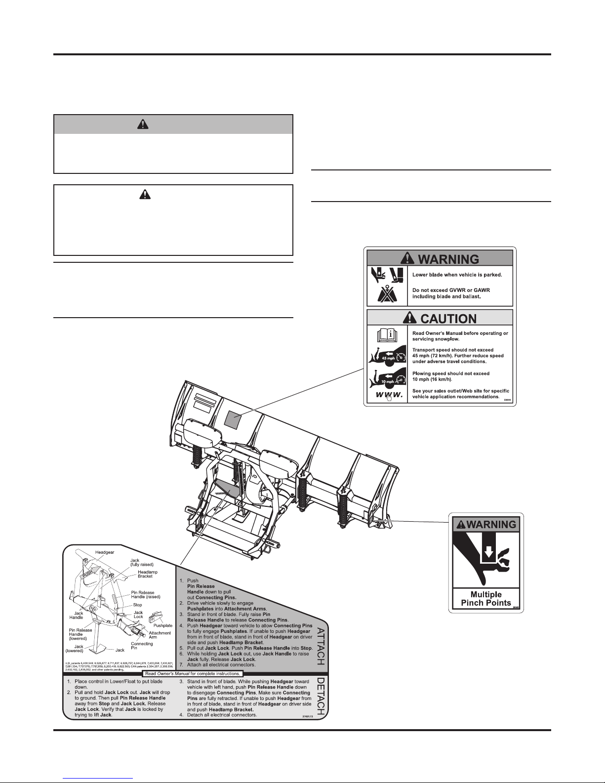
WARNING
Lower the blade when vehicle is parked.
Temperature changes could change
hydraulic pressure, causing the blade to
drop unexpectedly or damaging hydraulic
components. Failure to do this could result in
serious personal injury.
WARNING
Remove blade assembly before placing
vehicle on hoist.
WARNING
The driver shall keep bystanders clear of the
blade when it is being raised, lowered, or
angled. Do not stand between the vehicle and
the blade or within 8 feet of a moving blade. A
moving or falling blade could cause personal
injury.
WARNING
To prevent accidental movement of the blade,
always turn the control OFF whenever the
snowplow is not in use. The power indicator
light will turn OFF.
CAUTION
Refer to the eMatch tool for minimum vehicle
recommendations and ballast requirements.
WARNING
Do not exceed GVWR or GAWR including the
blade and ballast. The rating label is found on
the driver-side vehicle door cornerpost.
WARNING
Keep hands and feet clear of the blade and
A-frame when mounting or removing the
snowplow. Moving or falling assemblies could
cause personal injury.
WARNING
Gasoline is highly ammable and gasoline
vapor is explosive. Never smoke while
working on vehicle. Keep all open ames
away from gasoline tank and lines. Wipe up
any spilled gasoline immediately.
WARNING
Vehicle exhaust contains lethal fumes.
Breathing these fumes, even in low
concentrations, can cause death. Never
operate a vehicle in an enclosed area without
venting exhaust to the outside.

Lit. No. 95026, Rev. 01 4 March 15, 2018
7197‑1
NOISE
Airborne noise emission during use is below 70 dB(A)
for the snowplow operator.
VIBRATION
Operating snowplow vibration does not exceed
2.5 m/s2 to the hand‑arm or 0.5 m/s2 to the whole body.
1/4-20 10
91
54
1/4-28 12
11
71
5/16-1
81
50 212
5/16-2
41
70 240
3/8-16 269 376
3/8-24 29
74
20
7/16-1442
96
06
7/16-20
9/16-12
9/16-18
5/8-11
5/8-18
3/4-10
3/4-16
7/8-9
7/8-14 47
46
69
64
49
091-8
1-12 70
49
95
1/2-13
1/2-20
11.9
13.7
24.6
27.3
43.6
26.9
53.3
93
148
49.4
69.8
77.9
106.4
120.0
8.4
9.7
17.4
19.2
30.8
35.0
49.4
55.2
75.3
85.0
M6 x 1.00
M12 x 1.75
M8 x 1.25
M14 x 2.00
M10 x 1.50
M27 x 3.00
M22 x 2.50
M30 x 3.50
M24 x 3.00
M20 x 2.5011.1
19.5
38.5
67
107
7.7
613
778
1139
1545
450
428
562
796
1117
M33 x 3.50
M36 x 4.00
2101
2701
1468
1952
325
M16 x 2.00 231167
M18 x 2.50 318222
Recommended Fastener Torque Chart
Size Size
Torque (ft-lb)
Grade
5
Grade
8
Metric Fasteners Class 8.8 and 10.9
These torque values apply to fasteners
except those noted in the instructions.
Torque (ft-lb)
Grade
5
Grade
8
Size Size
Torque (ft-lb)
Class
8.8
Class
10.9
Torque (ft-lb)
Class
8.8
Class
10.9
Inch Fasteners Grade 5 and Grade 8
CAUTION
Read instructions before assembling.
Fasteners should be nger tight until
instructed to tighten according to the torque
chart. Use standard methods and practices
when attaching snowplow, including proper
personal protective safety equipment.
TORQUE CHART

Lit. No. 95026, Rev. 01 5 March 15, 2018
7197‑1
3. Remove the nuts from the bumper fastener
assembly on both sides of the vehicle. For both
driver‑side and passenger‑side mounts, align
the forward mount holes with the protruding
cap screws and guide the mounts onto their
respective fastener assembly. Loosely fasten by
reinstalling the original nuts.
If the vehicle was equipped with compatibility
brackets, reinstall one of the original bracket
cap screws through the rear hole of each mount
and the existing hole in the vehicle frame. Secure
with the original nut.
INSTALLATION INSTRUCTIONS
NOTE: For easier assembly and installation,
vehicle and all snowplow components should
be on a smooth, level, hard surface, such as
concrete.
1. Remove the lower plastic portion of the bumper.
Save all parts for reinstallation.
Vehicles equipped with tow hooks will need the
tow hooks and outer tow hook brackets removed.
These cannot be reinstalled with the snowplow
mount in place. Retain the tow hooks, brackets,
and fasteners for reinstallation if the mount is
removed. The inner tow hook brackets can remain
in place.
2. Remove the compatibility brackets from the frame,
if so equipped (see illustration below). Save the
brackets and hardware for the vehicle owner.
Compatibility
Bracket
Fastener
Assemblies
Compatibility Bracket
Cap Screw
Outer Tow Hook Bracket

Lit. No. 95026, Rev. 01 6 March 15, 2018
7197‑1
5. Using four 1/2" x 1‑1/2" cap screws and
1/2" locknuts, loosely fasten a thrust arm to the
outside of both mounts, connecting the stabilizer
brackets and the rear mount holes.
Thrust arms are interchangeable and can
install on either side of the vehicle. There is no
left or right side‑specic part.
Be sure to insert the cap screws through the
stabilizer brackets pointing inward from outside the
vehicle to ensure access to the M10 cap screws
for later tightening.
6. Install the cross bar with the horizontal leg on the
bottom using four 1/2" x 1‑1/2" cap screws and
1/2" locknuts as shown below. Keep fasteners
loose for now.
Cross Bar
1/
2" x 1-1/2" Cap Screws
1/2" Locknuts
Rear Mount Holes
4. Lower the stabilizer bar by removing the two cap
screws located on the bottom of the frame rail on
each side of the vehicle.
Position a stabilizer bracket between the bottom
of the frame rail and the stabilizer bar retainer for
both sides, facing inward as shown below.
Loosely fasten with the M10 cap screws provided.
NOTE: Thread provided M10 cap screws into
the underside vehicle frame weld nuts. Cross
threading will strip these nuts or fail nut weld.
Cap Screws
Vehicle Frame Hole
Stabilizer Bracket
Stabilizer Bar
Passenger's Side

Lit. No. 95026, Rev. 01 7 March 15, 2018
7197‑1
9. Trim any portion of the handles protruding through
the frame openings.
10. For all vehicles:
Measure the distance between the mounts
as shown below. This distance should be
30‑1/8" ± 3/16". Once the proper distance
is achieved, tighten the cross bar fasteners
according to the torque chart.
Tighten the M10 stabilizer bracket cap screws and
all remaining fasteners according to the torque
chart. Start at the front of the mount and work
rearward.
11. Notch the lower plastic portion of the bumper as
needed to accommodate the snowplow mounts
and snowplow. Reinstall using original vehicle
fasteners.
NOTE: After ve to ten hours of snowplow usage,
retorque all pushplate assembly fasteners.
7. On vehicles without compatibility brackets:
Clamp the rear of each mount tightly against
the bottom of the truck frame. Using the bottom
mount hole as a guide, drill a 17/32" diameter hole
through the bottom of the frame rail.
8. Trim the handle of a 1/2" x 1‑1/2" cap screw with
handle to 1‑1/2" long, as shown. Insert it into the
opening in the side of the frame rail and through
the 17/32" drilled hole in the bottom of the frame.
Loosely fasten with a 1/2" locknut.
Using the 11/16" diameter mount holes as guides,
drill an 11/16" diameter hole through the outer wall
of each frame rail.
Insert a 5/8" nut with handle through the opening
in the side of each frame rail and align with the
drilled holes. For each of the mounts, insert a
5/8" x 1‑1/2" cap screw through both the mount
hole and drilled hole in the frame rail, and thread
into the 5/8" nut with handle.
CAUTION
Before drilling any holes, check both sides
of the material for any wires, fuel lines, fuel
tanks, etc., that may be damaged by drilling.
30
-1/8" ± 3/16"
Outside
to Outside
Not to scale

Lit. No. 95026, Rev. 01 8 March 15, 2018
7197‑1
Fisher Engineering reserves the right under its product improvement policy to change construction or design details and furnish equipment
when so altered without reference to illustrations or specications used. Fisher Engineering or the vehicle manufacturer may require or
recommend optional equipment for snow removal. Do not exceed vehicle ratings with a snowplow. Fisher Engineering offers a limited
warranty for all snowplows and accessories. See separately printed page for this important information. The following are registered (®) or
unregistered (™) trademarks of Douglas Dynamics, LLC: FISHER®, Minute Mount® 2, XLS™.
Printed in U.S.A.
Fisher Engineering
50 Gordon Drive
Rockland, ME 04841‑2139
www.sherplows.com
A DIVISION OF FISHER, LLC
Table of contents
Other Fisher Automobile Accessories manuals
Popular Automobile Accessories manuals by other brands

SpeedTech Lights
SpeedTech Lights PA 100 AIR HORN instruction manual

Body Armor 4x4
Body Armor 4x4 5145 installation instructions

Metra Electronics
Metra Electronics 95-7863 installation instructions

Yakima
Yakima HoldUp Plus2 installation instructions

SEON
SEON HX16 installation guide

SAF-HOLLAND
SAF-HOLLAND Yard Spotter Series owner's manual