Fisher Minute Mount 2 LD Series User manual

Table of Contents
Safety Information .................................................................................................................... 2
Blade, Headgear, and A-Frame Assembly .............................................................................. 5
Hydraulic Unit Installation ....................................................................................................... 7
Snowplow Control Harness and Cable Installation ............................................................... 9
Headlamp Installation ............................................................................................................ 10
Final Adjustments................................................................................................................... 11
CAUTION
Read this document before installing the
snowplow.
CAUTION
See your FISHER®outlet for application
recommendations. The Kit Selection Guide has
specific vehicle and snowplow requirements.
Fisher Engineering
LD Series
Installation Instructions
P.O. Box 529 Rockland, Maine 04841 November 5, 2003
Lit. No. 26182
27750 LD
A DIVISION OF DOUGLAS DYNAMICS, L.L.C.

November 5, 2003 2 Lit. No. 26182
27750 LD
SAFETY DEFINITIONS
Read these instructions and labels on the snowplow
before beginning installation.
NOTE: Identifies tips, helpful hints, and
maintenance information the owner/operator
should know.
WARNING/CAUTION AND INSTRUCTION
LABELS
Become familiar with and inform users about the
warning labels on the back of the blade, and the
instruction label on the headgear.
Warning/Caution Label
Attachment
Arm
Jack
Lock
Headgear
Jack
(fully raised)
Jack (lowered)
Pin Release
Handle
(lowered)
Connecting
Pin
Pushplate
Jack
Stop
Pin Release
Handle (raised)
ATTACH DETACH
27451
1. Push Pin
Release
Handle down to pull
out Connecting Pins.
2. Drive vehicle slowly to engage
Pushplates into Attachment Arms.
3. Stand in front of blade. Fully raise Pin Release
Handle to release Connecting Pins.
4. Push Headgear toward vehicle to allow
Connecting Pins to fully engage Pushplates.
5. Pull out Jack Lock. Push Pin Release Handle
into Stop.
6. While holding Jack Lock out, use Jack Handle to
raise Jack fully. Release Jack Lock.
7. Attach all electrical connectors.
U.S Patents 4,280,062; 4,999,935; 5,353,530; 5,420,480; RE 35,700; 6,253,470;
CAN Patent 2,060,425; and other patents pending.
Read Owner's Manual For Complete Instructions
1. Place control in Lower/Float to put blade
down.
2. Pull and hold Jack Lock out. Jack will drop
to ground. Then pull Pin Release Handle
away from Stop and Jack Lock. Release
Jack Lock.
3. Stand in front of blade. While pushing
Headgear toward vehicle with left hand, push
Pin Release Handle down to disengage
Connecting Pins. Make sure Connecting
Pins are fully retracted.
4. Detach all electrical connectors.
WARNING
Indicates a potentially hazardous situation, that
if not avoided, could result in death or serious
personal injury.
CAUTION
Indicates a situation that, if not avoided, could
result in damage to product or property.
Instruction Label

Lit. No. 26182 3 November 5, 2003
27750 LD
SAFETY PRECAUTIONS
Improper installation and operation could cause
personal injury, and/or equipment and property
damage. Read and understand labels and the Owner's
Manual before installing, operating or making
adjustments.
PERSONAL SAFETY
• Wear only snug-fitting clothing while working on
your vehicle or snowplow.
• Do not wear jewelry or a necktie, and secure long
hair.
• Wear safety goggles to protect your eyes from
battery acid, gasoline, dirt and dust.
• Avoid touching hot surfaces such as the engine,
radiator, hoses and exhaust pipes.
• Always have a fire extinguisher rated BC handy, for
flammable liquids and electrical fires.
FIRE AND EXPLOSION
Be careful when using gasoline. Do not use gasoline to
clean parts. Store only in approved containers away
from sources of heat or flame.
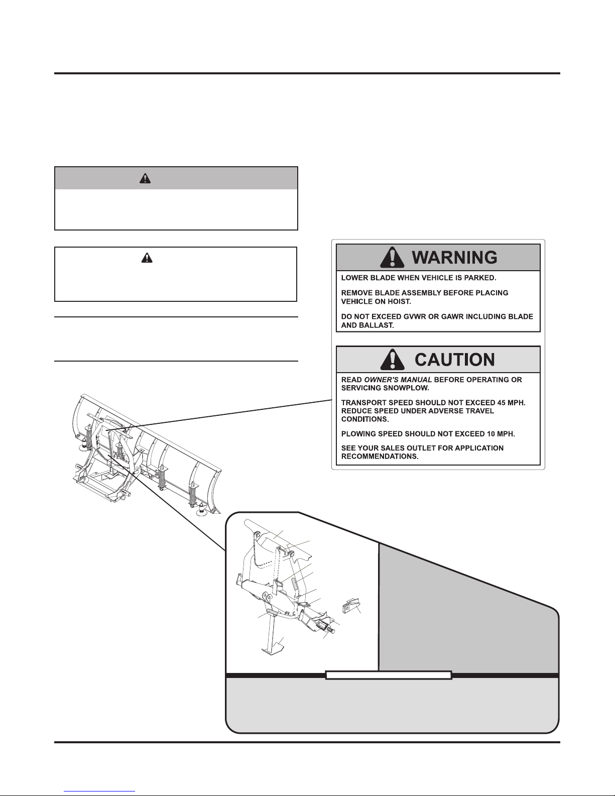
WARNING
Lower blade when vehicle is parked.
Temperature changes could change hydraulic
pressure, causing the blade to drop
unexpectedly or damaging hydraulic
components. Failure to do this could result in
serious personal injury.
WARNING
Remove blade assembly before placing vehicle
on hoist.
WARNING
The driver shall keep bystanders clear of the
blade when it is being raised, lowered or
angled. Do not stand between the vehicle and
the blade or within 8 feet of a moving blade. A
moving or falling blade could cause personal
injury.
WARNING
Keep hands and feet clear of the blade and
A-frame when mounting or removing the
snowplow. Moving or falling assemblies could
cause personal injury.
WARNING
Do not exceed GVWR or GAWR including the
blade and ballast. The rating label is found on
the driver-side vehicle door cornerpost.
CAUTION
Refer to the Kit Selection Guide for minimum
vehicle recommendations and ballast
requirements.
CAUTION
To prevent accidental movement of the blade,
always turn the ON/OFF switch to OFF
whenever the snowplow is not in use. The
control indicator light will turn off.
WARNING
Gasoline is highly flammable and gasoline
vapor is explosive. Never smoke while working
on vehicle. Keep all open flames away from
gasoline tank and lines. Wipe up any spilled
gasoline immediately.

November 5, 2003 4 Lit. No. 26182
27750 LD
HYDRAULIC SAFETY
VENTILATION TORQUE CHART
RecommendedFastenerTorque
Chart (Ft.-Lb.)
SizeSAE
Grade 2
SAE
Grade 5
SAE
Grade 8
1/4-20
5/16-18
3/8-16
3/8-24
7/16-14
1/2-13
9/16-12
5/8-11
3/4-10
7/8-9
1-8
6
11
19
24
30
45
66
93
150
150
220
9
18
31
46
50
75
110
150
250
378
583
13
28
46
68
75
115
165
225
370
591
893
MetricGrade 8.8 (Ft.-Lb.)
SizeTorqueSize
Torque
M6
M8
M10
M12
M14
M16
7
17
35
60
95
155
These torque values applyto fasteners
except those noted inthe instruction.
• Always inspect hydraulic components and hoses
before using. Replace any damaged or worn parts
immediately.
• If you suspect a hose leak, DO NOT use your hand
to locate it. Use a piece of cardboard or wood.
WARNING
Vehicle exhaust contains deadly carbon
monoxide (CO) gas. Breathing this gas, even in
low concentrations, could cause death. Never
operate a vehicle in an enclosed area without
venting exhaust to the outside.
WARNING
Hydraulic oil under pressure can cause skin
injection injury. If you are injured by hydraulic
oil, get medical attention immediately.
CAUTION
Read instructions before assembling. Fasteners
should be finger tight until instructed to tighten
according to the torque chart. Use standard
methods and practices when attaching
snowplow including proper personal protective
safety equipment.

Lit. No. 26182 5 November 5, 2003
27750 LD
Jack
Handle
Jack
Lock
Jack
BLADE, HEADGEAR, AND A-FRAME
ASSEMBLY
1. Place a 3/8" U-bolt on to extension spring. Place
3/8" nut on to each side of U-bolt. Place U-bolt
through crossbar on A-frame. Place 3/8" lock
washers and nuts on U-bolt and tighten.
2. Attach the A-frame to the blade. Insert the 1" x 8"
clevis pin down through the blade and A-frame and
secure with a 1/4" x 2" cotter pin.
3. Install a blade guide on each end of the top of the
blade. For each guide, put one washer and one nut
on either side of the blade.
4. Install the jack by pulling the jack lock out and
inserting the jack up through the slot in the
headgear. Release the jack lock to hold the jack in
place. Attach the jack handle to the jack with a 3/8"
lock washer and nut.
5. Align holes in headgear assembly with the middle
hole in the A-frame pushears. Attach the A-frame
to the headgear assembly with two steps pins and
1/4" x 1-1/2" cotter pins. Insert the step pins from
the outside of the headgear. Verification of proper
A-frame position will be made during Final
Adjustments at the end of these instructions.
Nut
Lock Washer
U-Bolt
Cross Bar
Extension Spring
Nut
1/4" x 1-1/2
"
Cotter Pin
A
-Frame
Pushear
Headgear
Assembly
Step
Pin

November 5, 2003 6 Lit. No. 26182
27750 LD
6. Install a 3/8" U-bolt through the last link in one end
of the lift chain. Attach U-bolt and chain to the
holes on the driver-side of the A-frame with two
3/8" lock washers and nuts. Tighten. The other end
of the lift chain will pass through the stop link on
the lift arm and then be attached to the passenger-
side of the A-frame after hydraulic unit is installed.
7. Insert the cable down through the hole in the strap
fork. Attach the strap fork to the hole in the stop
link on the lift arm with a 3/8" x 1" clevis pin and
1/8" x 1" cotter pin. Slip the cable thimble onto the
top loop in the spring previously installed in the
front of the A-frame.
NOTE: The slotted end of the thimble may need to
be opened to slip it onto the loop. Fully close the
slot after attaching the thimble to the spring.
View from bottom of A-frame.
Cable
Clevis Pin
Strap Fork
Cotter Pin
Stop Link
8. Loop the end of the cable around the thimble. Pull
the cable up against the thimble until the slack is
removed. Attach the end of the cable back onto
itself with two cable clamps loosely installed close
to the thimble as shown.
Due to varying vehicle heights, the length of the
cable must be adjusted for the vehicle in the Final
Adjustments section at the end of these
instructions.

Lit. No. 26182 7 November 5, 2003
27750 LD
HYDRAULIC UNIT INSTALLATION
Preparing Rams for Installation
1. Remove the plug from the ram port.
2. Turn the jam nut on the fitting as far back as
possible.
3. Lubricate the O-ring with clean hydraulic oil.
4. Screw fitting into port by hand as far as it will go.
The washer should contact port face and shoulder
of the jam nut threads.
5. Unscrew fitting to proper position, no more than
one full turn.
6. Use one wrench to hold the fitting body in position
and tighten the jam nut with another wrench until
the washer again contacts port face. Tighten 1/8 to
1/4 turn to lock fitting in place.
7. Attach 22" HP hose to lift ram. Attach a 32" HP
hose to the passenger-side ram. Attach a 42" HP
hose to the driver-side ram.
Fitting
Jam Nut
Washer
O-Ring
Ram
Attaching Lift and Angle Rams
1. Attach the lift ram to the headgear and lift arm with
two 1" x 3-5/16" clevis pins and 1/4" x 1-1/2" cotter
pins.
2. Attach the angle rams to the A-frame and blade
with the four anchor pins and cotter pins. Note
that the ram ports are on the inside, nearest the
A-frame.
AngleRam
1/4" x 2"
Cotter Pin
1" x 4"
Anchor Pin
1" x 4-3/4"
Anchor Pin
1/4" x 1-1/2"
Cotter Pin
1" x 3-5/16"
ClevisPin
Lift Ram

November 5, 2003 8 Lit. No. 26182
27750 LD
Cap Screw
Washer
Locknut
Mounting Hydraulic Unit
1. Bolt the Insta-Act®hydraulic unit to the headgear
using two 1/4" x 3" cap screws, flat washers, and
locknuts.
2. Remove the plugs from the angle ports, lift port and
the 3/8" NPTF plug from the breather port. Screw
the 90° swivel elbows into the angle ports and lift
port as shown. Screw the 3/8" NPTF x 90° street
elbow into the breather port .
3. Note the proper orientation of the elbows in the
photo below. The 1/4" x 90° swivel elbow in the lift
port should be at 12 o'clock. The 3/8" x 90° street
elbow in the breather port should point straight up.
Screw the 3/8" NPTF breather into the street
elbow.
Front View
Lift
Hose
DS Angle
Hose
PS
Angle
Hose
1/4" x 90°
Swivel Elbows
3/8" NPTF
Breather
Breather Port
Lift Port
AnglePorts
3/8" NPTF x 90°
Street Elbow

Lit. No. 26182 9 November 5, 2003
27750 LD
SNOWPLOW CONTROL HARNESS AND
CABLE INSTALLATION
NOTE: Use dielectric grease to prevent corrosion
on all electrical connections. Fill receptacles and
lightly coat ring terminals and blades before
assembly.
1. Remove the valve cover, and connect the
snowplow control harness to the valve coil
terminals according to the instructions inside the
valve cover.
NOTE: The strain relief must be inside the cover to
prevent unnecessary strain on the solenoid
connectors.
2. Apply anti-seize lubricant to the fasteners and
reinstall the valve cover.
3. Attach the snowplow battery cable to the motor
terminals. Connect the black and red striped wire to
the POSITIVE (+) terminal. Connect the black wire
to the NEGATIVE (–) terminal. Connect the smaller
black wire (from control harness) with the orange
stripe to the NEGATIVE (–) terminal of the motor.
4. Cable tie harnesses and battery cable to the
headgear as shown on the following page.
NOTE: Snowplow lighting and control harnesses
plug into one another for storage.
Three-Way
Green Wire
Two-Way
White/Yellow Wire
Black/Orange Wire to Each Coil
Four-Way
Blue Wire
4. Route hydraulic hoses as shown. Attach each
angle ram hose to the headgear near the hydraulic
unit with a clamp loop. Attach each clamp loop to
the headgear with a cap screw and locknut using
the holes provided.
Back View
Clamp
Loops
Lift
Hose
PS
Angle
Hose
DS Angle
Hose

November 5, 2003 10 Lit. No. 26182
27750 LD
HEADLAMP INSTALLATION
1. Slide a headlamp swivel onto the threaded stem on
the underside of the driver-side headlamp
assembly. The park/turn lamp should be to the
outside of the headlamp.
2. Mount the headlamp to the headgear light bracket
as shown. Secure with a lock washer and nut.
3. Repeat steps 1 and 2 on the passenger side.
4. Route the snowplow lighting harness as shown,
connecting the black/orange ground wire to the
NEGATIVE (–) motor terminal. Secure the
snowplow lighting harness to the headgear using
cable ties as needed.
5. Read, follow, and remove the headlamp label if
one is present.
WARNING
Your vehicle must be equipped with snowplow
headlamps and directional lights.
7
6
5
4
3
2
1
Cable
Ties
Cable
Boot
Cable
Ties
Cable Routing
1 Snowplow Lighting Harness
2 Black/Orange Wire
3 Black Wire
4 Black/Red Wire (connected to POSITIVE (+)
motor terminal)
5 Black/Orange Ground Wire (connected to
NEGATIVE (–) motor terminal)
6 Snowplow Battery Cable, shrouded plug (plug
into cable boot for storage)
7 Snowplow Control Harness (plug into snowplow
lighting harness for storage)
New StyleOldStyle

Lit. No. 26182 11 November 5, 2003
27750 LD
FINAL ADJUSTMENTS
1. Complete installation of lift chain by inserting the
loose end of lift chain through stop link on the lift
arm. Fasten to holes in the A-frame using a 3/8"
U-bolt, lock washer, and nut with the last link of the
chain. Adjust the lift chain to allow 6" extension of
lift rod and 2-3" slack in chain in the float mode.
Tighten.
2. Complete electrical installation in vehicle and install
control. Attach plow to vehicle.
3. Fill the hydraulic unit to top of fill hole with hydraulic
fluid.
System Capacity:
Reservoir – 1-3/4 quart
Complete System – 2-3/8 to 2-3/4 quarts
4. Raise and lower the snowplow several times. Be
sure to completely retract the lift ram each time.
Return to the lower position, retracting the lift ram
completely.
5. With the blade lowered, add more hydraulic fluid to
the reservoir. Keeping the blade to the ground,
angle the blade several times in each direction.
6. With the lift ram fully retracted, add enough
additional hydraulic fluid to bring fluid level to top of
fill hole.
7. With plow attached to properly ballasted vehicle
and blade lowered to ground, the A-frame should
be parallel with the ground. If not, reposition
A-frame using upper or lower pushear holes.
8. For reliable operation and to prevent damage to
the 6-1/2" lift arm retraction spring, the length of
the cable must be adjusted when attached to the
vehicle it will be used on. With the lift ram fully
collapsed, wrap the cable tightly around the
thimble, shorten/lengthen the cable to remove all
slack from the cable, then tighten the cable
clamps.
9. After adjustment, excess cable should be trimmed
off close to the second cable clamp. Cover cut end
of cable with electrical tape. Excessive spring
tension will make attaching/detaching difficult and
overextend the spring.
WARNING
Keep 8' clear of the blade when it is being
raised, lowered or angled. Do not stand
between the vehicle and blade or directly in
front of the blade. If the blade hits or drops on
you, you could be seriously injured.
CAUTION
Do not mix different types of hydraulic fluid.
Some fluids are not compatible and may cause
performance problems and product damage.

November 5, 2003 12 Lit. No. 26182
27750 LD
Fisher Engineering reserves the right under its product improvement policy to change construction or design details and furnish equipment when
so altered without reference to illustrations or specifications used. Fisher Engineering and the vehicle manufacturer may require and/or recommend
optional equipment for snow removal. Do not exceed vehicle ratings with a snowplow. Fisher Engineering offers a limited warranty for all
snowplows and accessories. See separately printed page for this important information. The following are registered (®) trademarks of Douglas
Dynamics, L.L.C.: FISHER®, Insta-Act®, Minute Mount®2.
Printed in U.S.A.
Table of contents
Other Fisher Automobile Accessories manuals