Lit. No. 44227, Rev. 10 4 June 1, 2008
44600-1, 44650-1, 44675-1, 44685-1, 44695-1, 44775-1, 44785-1, 44795-1
VENTILATION
BATTERY SAFETY
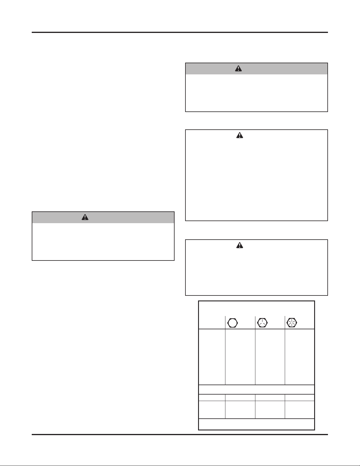
TORQUE CHART
Recommended Fastener Torque
Chart (ft-lb)
Size SAE
Grade 2
SAE
Grade 5
SAE
Grade 8
1/4-20
5/16-18
3/8-16
3/8-24
7/16-14
1/2-13
9/16-12
5/8-11
3/4-10
7/8-9
1-8
6
11
19
24
30
45
66
93
150
150
220
9
18
31
46
50
75
110
150
250
378
583
13
28
46
68
75
115
165
225
370
591
893
Metric Grade 8.8 (ft-lb)
Size TorqueSize
Torque
M 6
M 8
M 10
M 12
M 14
M 16
7
17
35
60
95
155
These torque values apply to fasteners
except those noted in the instruction.
PERSONAL SAFETY
• Remove ignition key and put the vehicle in park or
in gear to prevent others from starting the vehicle
during installation or service.
• Wear only snug-fitting clothing while working on
your vehicle or snowplow.
• Do not wear jewelry or a necktie, and secure long
hair.
• Wear safety goggles to protect your eyes from
battery acid, gasoline, dirt and dust.
• Avoid touching hot surfaces such as the engine,
radiator, hoses and exhaust pipes.
• Always have a fire extinguisher rated BC handy,
for flammable liquids and electrical fires.
FIRE AND EXPLOSION
Be careful when using gasoline. Do not use gasoline
to clean parts. Store only in approved containers away
from sources of heat or flame.
CELL PHONES
A driver's first responsibility is the safe operation of
the vehicle. The most important thing you can do
to prevent a crash is to avoid distractions and pay
attention to the road. Wait until it is safe to operate
Mobile Communication Equipment such as cell
phones or two-way radios.
CAUTION
Batteries normally produce explosive gases
which can cause personal injury. Therefore,
do not allow flames, sparks or lit tobacco
to come near the battery. When charging or
working near a battery, always cover your
face and protect your eyes, and also provide
ventilation.
Batteries contain sulfuric acid which burns
skin, eyes and clothing.
Disconnect the battery before removing or
replacing any electrical components.
CAUTION
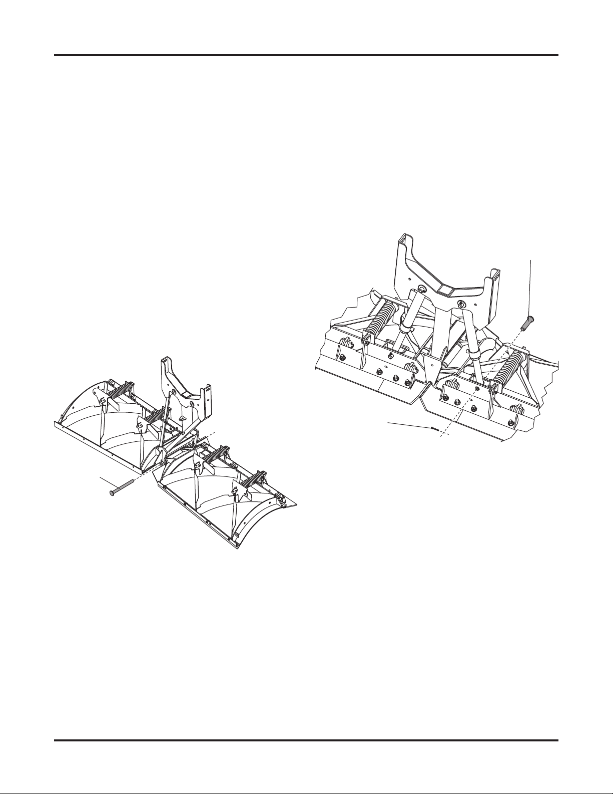
Read instructions before assembling.
Fasteners should be finger tight until
instructed to tighten according to torque
chart. Use standard methods and practices
when attaching snowplow including proper
personal protective safety equipment.
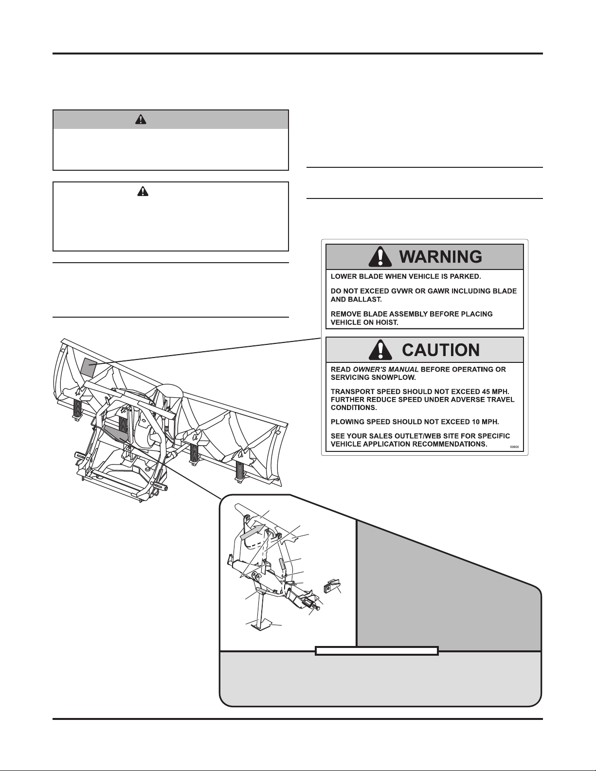
WARNING
Vehicle exhaust contains lethal fumes.
Breathing these fumes, even in low
concentrations, can cause death. Never
operate a vehicle in an enclosed area without
venting exhaust to the outside.
WARNING
Gasoline is highly flammable and gasoline
vapor is explosive. Never smoke while
working on vehicle. Keep all open flames
away from gasoline tank and lines. Wipe up
any spilled gasoline immediately.