Instruction Manual
D103211X012
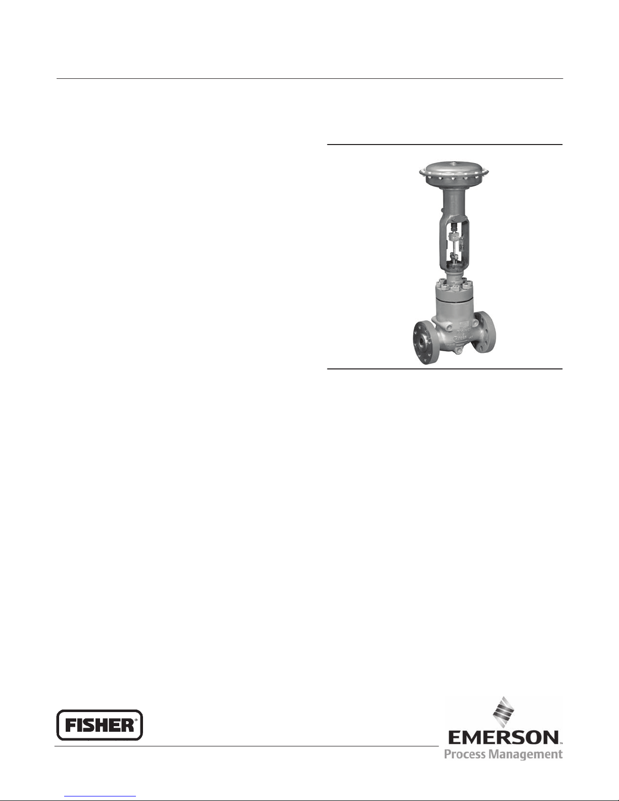
NotchFlo DST Valve
March 2011
9
Adding Packing Rings
WARNING
Refer to the WARNING at the beginning of the Maintenance section in this instruction manual.
To avoid personal injury or equipment damage resulting from packing leakage, inspect the valve plug stem and packing box
wall for nicks or scratches while performing the following procedures.
Use care to avoid damaging these surfaces.
Key numbers referred to in this procedure are shown in figures 7 through 12, unless otherwise indicated.
When using packing with a lantern ring (key 24) it may be possible to add packing rings above the lantern ring as a
temporary measure without removing the actuator from the valve body.
1. Isolate the control valve from the line pressure, release pressure from both sides of the valve body, and drain the
process media from both sides of the valve. If using a power actuator, also shut‐off all pressure lines to the power
actuator, release all pressure from the actuator. Use lock‐out procedures to be sure that the above measures stay in
effect while you work on the equipment.
2. Remove the packing flange nuts (key 21) and lift the packing flange, upper wiper, and packing follower (keys 19,
27, and 28) away from the valve body.
3. It may be possible to dig out the old packing rings on top of the lantern ring, but use care to avoid scratching the
valve plug stem or packing box wall. Clean all metal parts to remove particles that would prevent the packing from
sealing.
4. Remove the stem connector and slip the packing rings over the end of the valve plug stem.
5. Reassemble the packing follower, upper wiper, packing flange, and packing flange nuts (keys 28, 27, 19, and 21).
6. Reconnect the body‐actuator stem connection according to the appropriate actuator instruction manual.
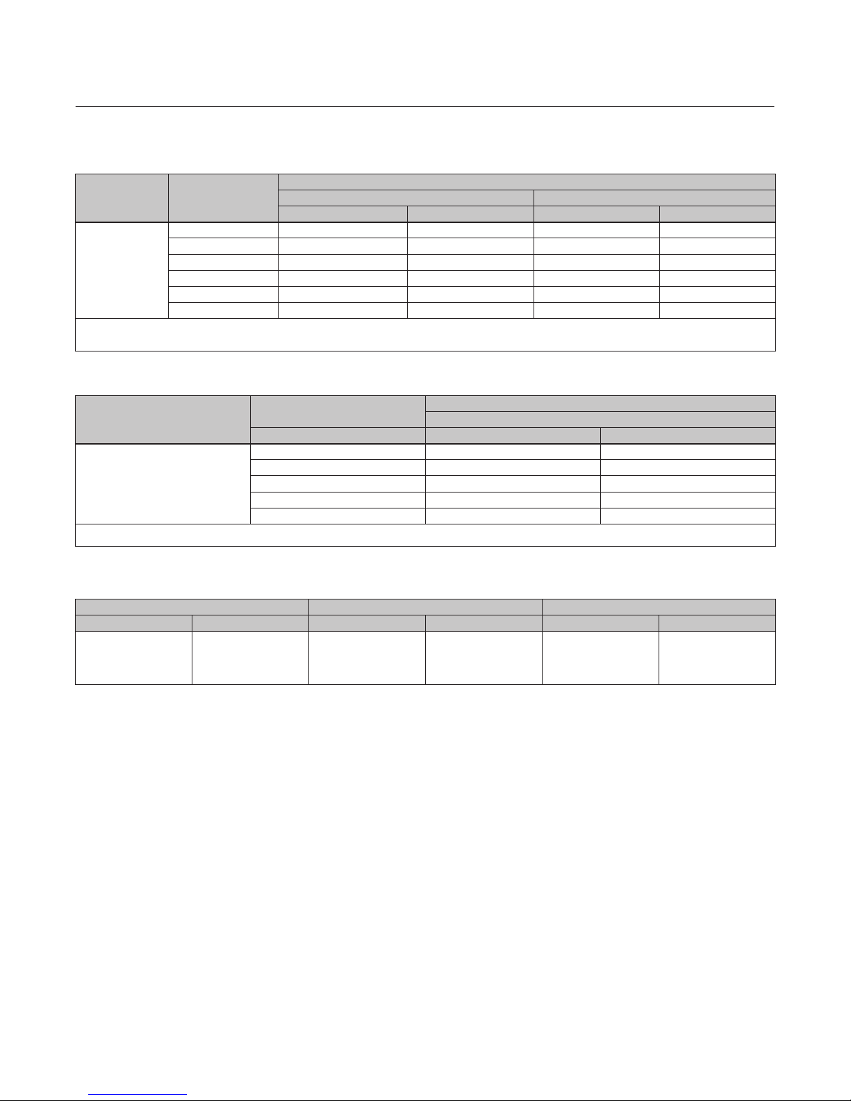
7. Tighten the packing flange nuts only far enough to stop leakage under operating conditions. Check for leakage
around the packing follower when the valve is being put into service. Retighten the packing flange nuts as required
(see table 3 or 4).
Replacing Packing
WARNING
Refer to the WARNING at the beginning of the Maintenance section in this instruction manual.
To avoid personal injury or equipment damage resulting from packing leakage, inspect the valve plug stem and packing box
wall for nicks or scratches while performing the following procedures.
Use care to avoid damaging these surfaces.
Key numbers referred to in this procedure are shown in figures 7 through 12, unless otherwise indicated.
1. Isolate the control valve from the line pressure, release pressure from both sides of the valve body, and drain the
process media from both sides of the valve. If using a power actuator, also shut‐off all pressure lines to the power
actuator, release all pressure from the actuator. Use lock‐out procedures to be sure that the above measures stay in
effect while you work on the equipment.
2. Remove the cap screws in the stem connector, and separate the two halves of the stem connector. Then exhaust all
actuator pressure, if any was applied, and disconnect the actuator supply and any leakoff piping.